Modbus RTU to DNP3 protocol conversion
Setup
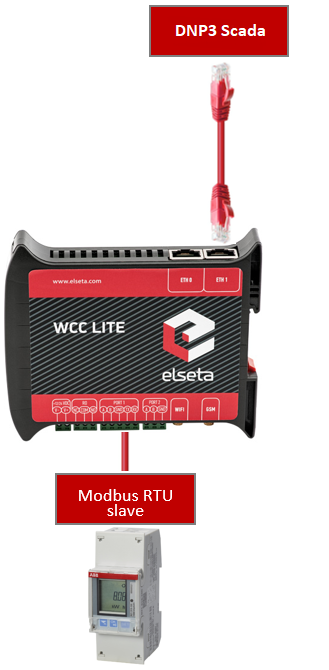
The article describes WCC Lite configuration steps to enable Modbus RTU protocol conversion to DNP3 serial.
Before you begin, make sure you have completed all physical installation work according to the manufacturer's installation instructions.
Set up your computer and connect the Ethernet cable to the WCC Lite ETH0 port. Log in with default credentials and set up basic required settings (name, network, users, etc.). You can find configuration tutorials in How to articles.
To prepare the configuration, fill in the information in both the Devices and Signals sheets:
Configuring Devices
Add a connected ABB meter with the Modbus RTU protocol required information:
| name | description | device_alias | enable | protocol | id | device | baudrate | databits |
| From ABB Meter | ABB B21 | B21 | 1 | Modbus RTU | 1 | PORT1 | 9600 | 8 |
| stopbits | parity | flowcontrol | scan_rate_ms | serial_delay | retry_count |
| 1 | none | none | 5000 | 200 | 3 |
Add the SCADA working on the DNP3 protocol required information:
| name | device_alias | enable | protocol | mode | bind_address |
| DNP3 | DNP3_SCADA | 1 | DNP3 TCP slave | TCP | 0.0.0.0 |
| host | port |
source_address |
unsol_classes |
| 192.168.1.1
|
20000 | 1 | 1,2,3 |
You can find more options and descriptions of the settings in the Device configuration article.
Configuring Signals
Add connected meter measurements information. Use the meter manual for information and addresses (tag_job_todo).
| signal_name | device_alias | signal_alias | enable | multiply | log | job_todo | tag_job_todo | number_type |
| Voltage | B21 | U | 1 | 0.1 | 1 | 3;23296;2 | 3;23296;2 | UNSIGNED32 |
| Current | B21 | I | 1 | 0.01 | 1 | 3;23308;2 | 3;23308;2 | UNSIGNED32 |
| Active power | B21 | P | 1 | 0.00001 | 1 | 3;23316;2 | 3;23316;2 | SIGNED32 |
| Frequency | B21 | F | 1 | 0.01 | 1 | 3;23340;1 | 3;23340;1 | UNSIGNED16 |
| Power factor | B21 | Cos | 1 | 0.001 | 1 | 3;23354;1 | 3;23354;1 | SIGNED16 |
| Active import | B21 | E | 1 | 0.01 | 1 | 3;20480;4 | 3;20480;4 | FLOAT |
job_todo -Request to send according to Modbus specification without device address and checksum;
tag_job_todo - a subset of the job_todo field, exact address of measurement (tag)
Add DNP3 master signals information:
| signal_name | device_alias | signal_alias | source_device_alias | source_signal_alias |
| Voltage | dnp3 | dnp3_1001 | B21 | U |
| Current | dnp3 | dnp3_1002 | B21 | I |
| Active power | dnp3 | dnp3_1003 | B21 | P |
| Frequency | dnp3 | dnp3_1004 | B21 | F |
| Power factor | dnp3 | dnp3_1005 | B21 | Cos |
| Active import | dnp3 | dnp3_1006 | B21 | E |
| enable | log | index | signal_type | static_variation | event_variation | class_num |
| 1 | 1 | 1 | analog | 1 | 1 | 13 |
| 1 | 1 | 2 | analog | 1 | 1 | 13 |
| 1 | 1 | 3 | analog | 1 | 1 | 13 |
| 1 | 1 | 4 | analog | 1 | 1 | 13 |
| 1 | 1 | 5 | analog | 1 | 1 | 13 |
| 1 | 1 | 6 | analog | 1 | 1 | 13 |
Uploading the Configuration
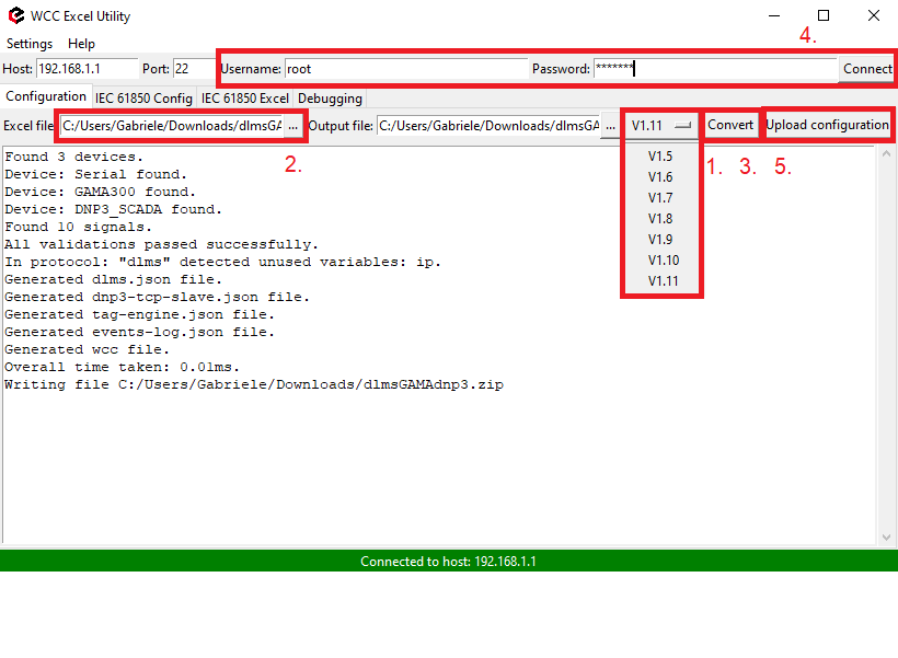
After configuring all devices and signals, follow these steps to check and upload the configuration using the WCC Excel Utility:
- Download and run WCC Excel Utility.
- Select the firmware version from the drop-down menu.
- Select the Excel file from your computer and click Convert.
- Check if no events in red colour occur. If so, edit the Excel file according to the event text and repeat Step 2.
- Enter the Host and credentials of WCC Lite, click connect and then Upload configuration.
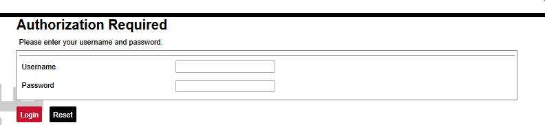
Another method to upload the configuration is via the web interface:
- Access the WCC Lite interface via your browser. The default IP address is 192.168.1.1. Enter credentials:
- Upload the Excel configuration:
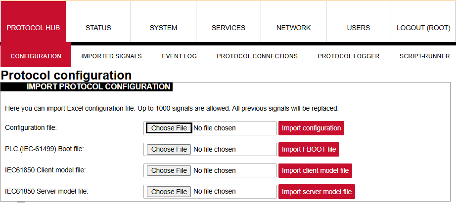
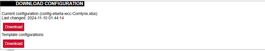
- After a successful upload, the configuration will appear under the DOWNLOAD CONFIGURATION tab:
- If any errors occur during the upload, follow the error messages and fix them according to Excel utility guidelines.


