M-Bus Serial Communication Setup Guide
Description
This article describes how to establish communication between WCC Lite and a meter using the Meter-Bus protocol.
Physical Link Setup: WCC Lite to Meter Connection
Set up your computer and connect Ethernet cable to WCC Lite ETH0 port. Login with default credentials and setup basic required settings (name, network, users, etc. ). You can find configuration tutorials in How to articles.
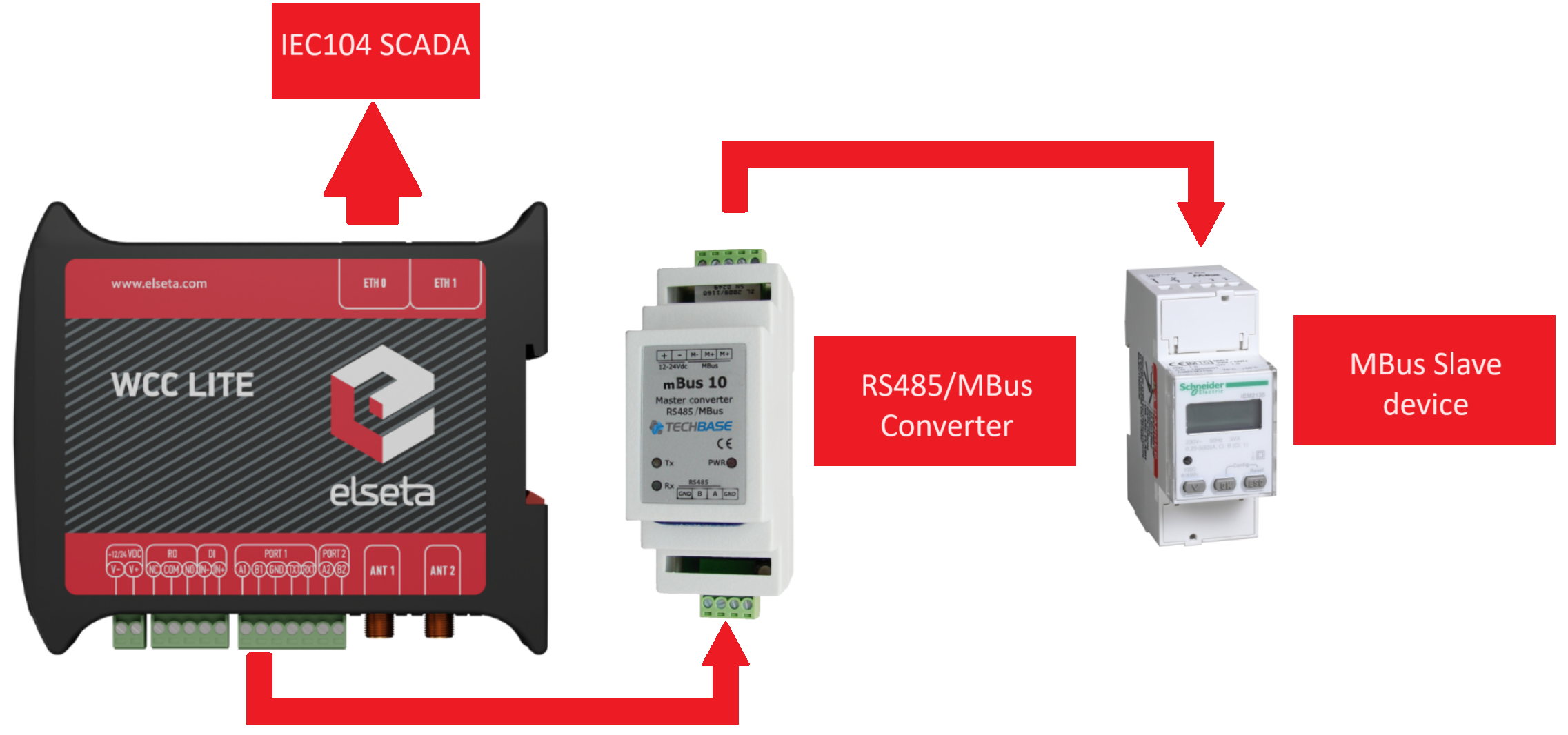
The WCC Lite lacks a built-in hardware interface for M-Bus connectivity, requiring the use of an RS485 or RS232 to M-Bus Master Converter for establishing a connection.
In the illustrated example, a Schneider IEM2135 meter was used alongside the M-Bus 10 RS485/M-Bus Master Converter for data exchange.
Example
When the meter configuration parameters match the ones in the Excel sheet, communication can be established. In the example, we also set up IEC104_SCADA communication along with M-Bus for smooth integration with the IEM2135 meter.
Configuration for the example showed in the illustration -> Download
The guidelines for creating your own configuration will be presented in the following segment.
Configuration
M-Bus parameters for Device tab
| Parameter |
Type |
Description |
Required |
Default value (when not specified) |
Range |
|
|
Min |
Max |
|||||
| name | string | User-friendly device name | Yes |
|
|
|
| description | string | Description of a device | No |
|
|
|
| device_alias | string | Alphanumeric string to identify a device | Yes | |||
| enable | boolean | Enabling/disabling a device | No | 1 | 0 | 1 |
| protocol | string | Protocol to be used. | Yes | mbus serial | ||
| scan_rate_ms | integer | All reads and writes will be executed within the timeframe in milliseconds. | No | 10000 |
|
|
| poll_delay_ms | integer | Minimum time delay in milliseconds to wait before sending any data on port. |
No | 200 |
|
|
| timeout_ms | integer | Timeout of waiting for an incoming response in milliseconds | Yes | 0 | 60000 | |
| address | integer | Device address | Yes | |||
| device | string | Communication port | Yes | PORT1 | PORT2 | |
| baudrate | integer |
Communication speed, baud/s |
Yes |
9600 |
300, 600, 1200, 2400, 4800, 9600, 19200, 38400, 57600, 115200 |
|
| databits | integer |
Data bit count for communication |
Yes |
8 |
6 |
9 |
| stopbits | integer |
Stop bit count for communication |
Yes |
1 |
1 |
2 |
| parity |
string |
Communication parity option |
Yes |
none |
none, even, odd |
|
M-Bus parameters for the Signals tab
| Parameter |
Type |
Description |
Required |
Default value (when not specified) |
Range |
|
|
Min |
Max |
|||||
| signal_name |
string |
User-friendly signal name |
Yes |
|
|
|
| device_alias |
string |
Device alias from a Devices tab |
Yes |
|
|
|
| signal_alias |
string |
Unique alphanumeric name of the signal to be used |
Yes |
|
|
|
| enable |
boolean |
Enabling/disabling of an individual signal |
No | 1 |
0 |
1 |
| log |
integer |
Enable logging in the event log |
No | 0 |
|
|
| number_type | string | Type of a number (FLOAT, DOUBLE, DIGITAL, etc.) | Yes | |||
| job_todo |
string |
Tag job as single or multiple comma-separated OBIS codes |
Yes |
|
|
|
| tag_job_todo | string | Tag sub job | Yes | |||
Optional parameters for signals are available on this page -> Optional parameters for signals.
If you wish to include mathematical expressions in your signals, the guidelines can be found on this page -> Mathematical functions.
Debugging
If M-Bus does not work properly (e.g. no communication between devices, data is corrupted, etc.), a user can launch a debug session from command-line interface and find out why the link is not functioning properly.
On the web interface's protocol connections page, M-bus devices will not be displayed. If the connection is established correctly, it can be observed on the imported signals page.
To launch a debugging session, a user should stop the pooler process and run the pooler command with respective flags.
- Step 1: Open the command terminal on your computer.
- Step 2: Connect via SSH, example of the command ssh root@192.168.1.1 and then enter your designated password.
- Step 3: Service must be stopped by entering the following command into the wcclite:
/etc/init.d/pooler stop - Step 4: After service is stopped it must be started with the preferred configuration file (JSON
files found in /etc) and a debug level 7: pooler -c /etc/pooler/pooler.json -d7 - Step 5: Once the problem is diagnosed normal operations can be resumed with the following command: /etc/init.d/pooler start
POOLER command line debugging options
-h [ ––help ] Display help information
-V [ ––version ] Show version
-d<debug level> Set debugging level
-c [ ––config ] Config path
-s [ ––serial ] Show serial port data
-r [ ––raw ] Show raw telegram data
-B [ ––mbus ] Show M-Bus driver output
One example of debugging involves using the following command -> pooler -c /etc/pooler/pooler.json -B -d7 -s.
In this mode, both request packets and received packets are visible, along with the M-Bus driver output showing translated signal values received. This information can be instrumental in determining the correct configuration for the signal sheet. Additionally, messages regarding incorrect M-Bus frames can be observed, aiding in identifying potential wiring mistakes.