DLMS Serial to IEC61850-server protocol conversion (Wcc Lite FW: 1.7.0)
Description
The article describes WCC Lite configuration steps to enable DLMS Serial protocol conversion to IEC 61850-server.
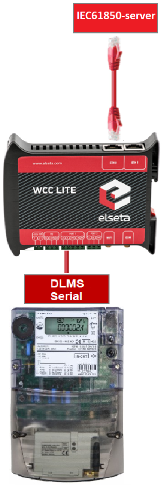
Fig 1. Connecting Meter with DLMS serial protocol to Wcc Lite and IEC61850 server
First steps
Before you begin, make sure you have completed all physical installation work according to the manufacturer's installation instructions.
Set up your computer and connect Ethernet cable to WCC Lite ETH0 port. Login with default credentials and setup basic required settings (name, network, users, etc.). You can find configuration tutorials in How to articles.
To prepare configuration fill information in both - Devices and Signals sheets:
Configure devices (excel "Devices" sheet)
Add required information for connected Gama meter with DLMS Serial protocol:
| name | description | device_alias | protocol | serial_number | device | databits | stopbits | baudrate | parity |
| DLMS Serial | DLMS Serial | DLMS_Meter | DLMS | 2250259 | PORT1 | 8 | 1 | 4800 | none |
| flowcontrol | enable | auth | logical_address | address_size | client_address | type | mode |
| none | 1 | LOW | 1 | 2 | 32 | SN | DLMS-HDLC |
More information concerning DLMS protocol configuration is provided in DLMS/COSEM article.
Add IEC 61850 server protocol required information:
| name | description | device_alias | protocol | bind_address |
| IEC 61850 Server | IEC 61850 Server | iec_61850_server | iec 61850 server | 0.0.0.0 |
| ied_name | access_point | port | auth |
host |
model_filename |
| WCCLITE | LD0 | 102 | NONE | 192.168.1.2 | WCC |
More information concerning IEC 61850 server protocol configuration is provided in IEC 61850 server article.
Configure signals (Excel "Signals" sheet)
The signals for all devices can be separated to different excel sheets for different device or listed in one excel sheet. In this case signals will be separated to SignalsDLMS and SignalsIEC61850 excel sheets. Make sure that these excel sheet names for different device signals always must start with word Signals. The example template for this case is added at the end of this article.
Add signals information for connected meter with DLMS Serial protocol
(Excel SignalsDLMS sheet):
| signal_name | device_alias | signal_alias | obis_job |
| Voltage L1-N | DLMS_Meter | Voltage_L1-N | 1.0.32.7.0.255 |
| Voltage L2-N | DLMS_Meter | Voltage_L2-N | 1.0.52.7.0.255 |
| Voltage L3-N | DLMS_Meter | Voltage_L3-N | 1.0.72.7.0.255 |
| Frequency | DLMS_Meter | Frequency | 1.0.14.7.0.255 |
| Current L3 | DLMS_Meter | Current_L3 | 1.0.71.7.0.255 |
obis_job - Objects are identified with the help of OBIS (Object Identification System) codes.
- The first number of OBIS code defines the media (energy type) to which the metering is related. Nonmedia
related information is handled as abstract data. For example all obis_jobs in the table above starts with numbers 1 which stands for "Electricity related objects". - The second number defines the channel number, i.e. the number of the input of a metering
equipment having several inputs for the measurement of energy of the same or different types
(e.g. in data concentrators, registration units). Data from different sources can thus be
identified. The definitions for this value group are independent from the value of the first number. In all obis_jobs from the table above second number is set to zero which means that no channel is specified. - The third number defines the abstract or physical data items related to the information
source concerned, for example current, voltage, power, volume, temperature. The definitions
depend on the value of the first number. For example in obis_jobs from the table above number 72 means voltage L3 and number 14 means frequency. - The forth number defines types, or the result of the processing of physical quantities
identified with the numbers 1 and 3, according to various specific algorithms. The
algorithms can deliver energy and demand quantities as well as other physical quantities. In all obis_jobs from the table above forth number is set to 7 which stands for "Instantaneous value". - The value of the fifth number defines further processing or classification of quantities identified by numbers 1 to 4. In case of the first obis_job number 0 means that all harmonics of the signal along with its fundamental frequency are going to be taken into consideration.
- The value of the sixth number defines the storage of data, identified by numbers 1 to 5, according to
different billing periods. Where this is not relevant, this value group can be used for further
classification. In all obis_jobs from the table above last number is set to 255 which means that data is not used.
Add signals information for IEC 61850 server (Excel SignalsIEC61850 sheet):
| signal_name | device_alias | signal_alias | source_device_alias | source_signal_alias |
| LD0__GGIO_5_AnIn1_mag.f | iec_61850_server | LD0__GGIO_5_AnIn1_mag.f | DLMS_Meter | Voltage_L1-N |
| LD0__GGIO_5_AnIn2_mag.f | iec_61850_server | LD0__GGIO_5_AnIn2_mag.f | DLMS_Meter | Voltage_L2-N |
| LD0__GGIO_5_AnIn3_mag.f | iec_61850_server | LD0__GGIO_5_AnIn3_mag.f | DLMS_Meter | Voltage_L3-N |
| LD0__GGIO_5_AnIn4_mag.f | iec_61850_server | LD0__GGIO_5_AnIn4_mag.f | DLMS_Meter | Frequency |
| LD0__GGIO_5_AnIn5_mag.f | iec_61850_server | LD0__GGIO_5_AnIn5_mag.f | DLMS_Meter | Current_L3 |
| ld_instance | ln_class | ln_instance | cdc | data_object | da_fc | number_type | da_value | Log |
| LD0 | GGIO | 5 | MV | AnIn1 | MX | FLOAT32 | mag.f | 1 |
| LD0 | GGIO | 5 | MV | AnIn2 | MX | FLOAT32 | mag.f | 1 |
| LD0 | GGIO | 5 | MV | AnIn3 | MX | FLOAT32 | mag.f | 1 |
| LD0 | GGIO | 5 | MV | AnIn4 | MX | FLOAT32 | mag.f | 1 |
| LD0 | GGIO | 5 | MV | AnIn5 | MX | FLOAT32 | mag.f | 1 |
From the table above it can be seen that IEC 61850 server signals has source_device_alias and source_signal_alias in which device_alias and signal_alias of DLMS meter signals are described. That is how DLMS meter signals are linked to IEC61850 server signals, so the measurements of the DLMS meter could be transported to IEC 61850 server.
For more detailed DLMS protocol communication analysis Gurux DLMS Director application can be used.
ICD file for IEC 61850 server
IED Capability Description (ICD) files are a specific type of Substation Configuration Language (SCL) file, containing a generic description of the whole capability range of a given device, including the functions and objects it can support. These ICD files can be found on internet, edited and adapted for current project. In this case the ICD file with 2 analog signals was edited, so it could have 5 analog signals for DLMS measurements. For that purpose, 3 additional signals was described in ICD file, so 5 analog signals could be linked with signals from DLMS. The ICD file and added signals are shown in Fig. 2. If it is needed to have more analog or other type of signals, the ICD file must be analyzed and signals added to the correct place of the file.
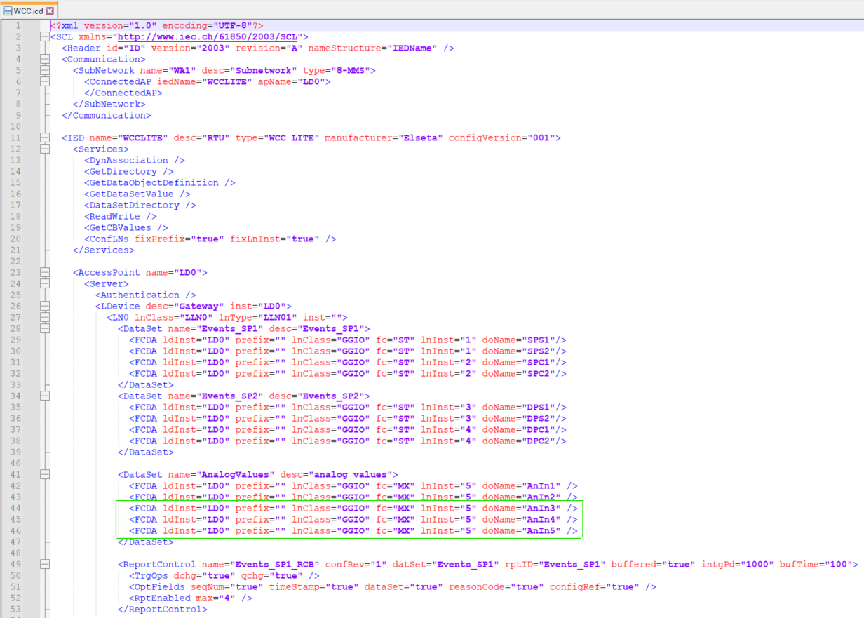
Fig. 2 Editing the ICD file
This ICD file will be used for creating the IEC 61850 server model file, which later will be uploaded to Wcc Lite. Also the ICD file will be uploaded to IEDscout app, for simulating the client. Other apps for simulation of client can be used as well.
Generating Server Model file for Wcc Lite
For this step, Wcc Excel Utility app will be used. Firstly open Wcc Excel Utility app and choose version 1.7 in "Configuration" tab.
Fig. 3 Choosing the right version
Second step is to go to IEC61850 Config tab, choose the ICD file that is needed and Output file directory of Server Model file. The name of output file should be the same as the name specified in the Excel configuration "Devices" tab "model_filename" for IEC 61850 server. The extension of Server Model file using Wcc Lite 1.7.0 firmware should be .cfg but using newer version of Wcc Excel Utility the extension .server can be created by default. This can be changed by editing the Server Model file name. Now "convert" button needs to be pressed and the Server Model file will be generated (Fig. 4). After that, this Server Model file needs to be uploaded to Wcc Lite WEB (Fig. 5).
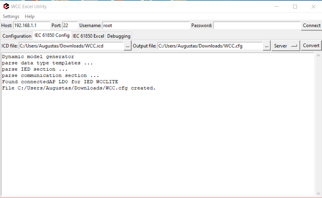
Fig. 4 Generating Server Model file
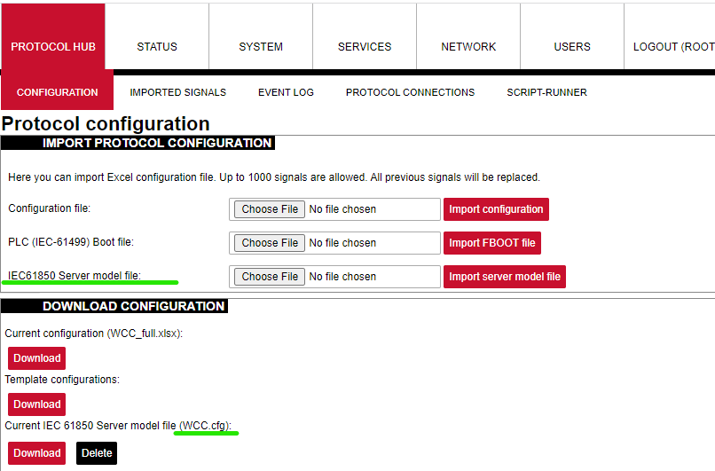
Fig. 5 Uploading IEC 61850 Server Model file to Wcc Lite WEB
Uploading Wcc Lite configuration
After the Server Model file is uploaded, and made sure that Server Model file name matches the one specified in excel configuration we are now able to upload excel configuration to Wcc Lite. One more thing to notice, in Excel configuration "Devices" sheet "host" parameter for IEC61850 server is 192.168.1.2. This IP should match the PC Ethernet IP, to which Wcc Lite ETH0 port is connected via ETH cable and can be set manually. This is shown in Fig. 6.
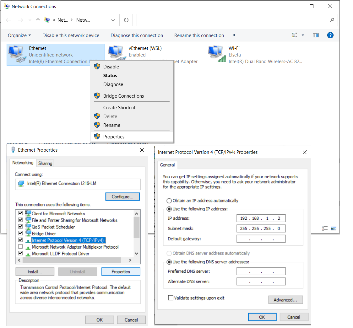
Fig. 6 Changing PC IP (TCP/IPv4) to match the Host IP in configuration
When all parameter described earlier matches the ones specified in configuration, we can upload the configuration to Wcc Lite WEB. It is shown in Fig. 7. Simply choose the Excel configuration and press "import configuration". The upload may take several minutes.
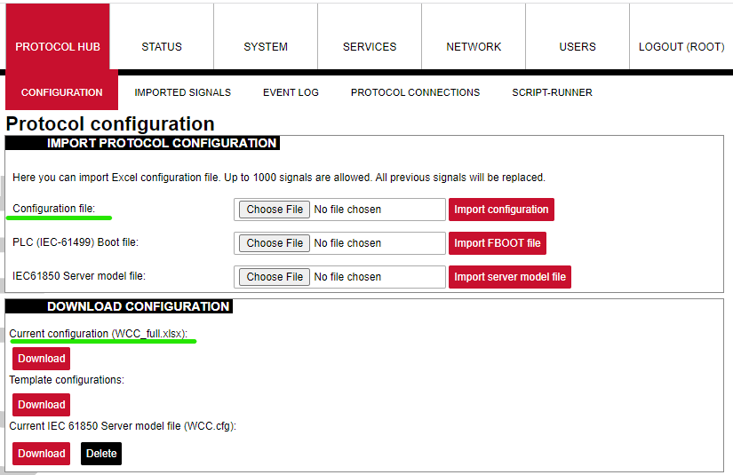
Fig. 7 Uploading Excel configuration to Wcc Lite.
Starting IEC 61850 server
Now, when needed files were uploaded to Wcc Lite, we can start IEC61850 server. For this step the debugger interface will be needed. We prefer using terminal window with installed linux subsystem or other debugger interfaces like PuTTY app. These apps can be found and downloaded on the internet. Firstly we need to connect to Wcc Lite through SSH (using PuTTY, SSH connection type should be chosen and Wcc Lite IP 192.168.1.1 entered). Following commands should be entered in the debugger window:
1. Connecting to Wcc Lite: ssh root@192.168.1.1
2. Login: root Password: your Wcc Lite pasword
3. Stopping the IEC 61850 service: /etc/init.d/iec61850-server stop
4. Starting IEC61850 server in debugger mode: iec61850-server -c /etc/iec61850-server/iec61850-server.json -d7
After these commands are executed, the IEC 61850 server is started, it is shown in Fig. 8.
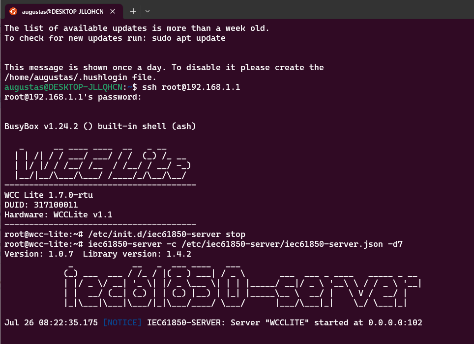
Fig. 8 Connecting to Wcc Lite through SSH and starting IEC61850 server
Connecting to Wcc Lite (server) on IEDscout (client)
For this step, IEDscout will be needed. IEDScout is an ideal tool for protection and substation automation engineers working with IEC 61850 devices. It provides access to the IEDs (Intelligent Electronic Devices) and performs numerous useful functions when working with them. The software can simulate entire Ed. Also any different but similar functionality software can be used as well. Following steps are done using IEDscout software.
1. Open IEDscout software, then choose and open ICD file that is needed.
2. In opened IEDscout Browser window click "Discover IED", then in opened window enter Wcc Lite IP (192.168.1.1) and press "discover" (Fig. 9).
3. If the Wcc Lite did not connect when "discover" was pressed, then it is needed to press "Online". The indication, that IEC61850 server and Meter with DLMS serial protocol are connected correctly can be seen in Wcc Lite WEB "protocol connections" tab (Fig. 10).
Now Wcc Lite IEC61850 server and IEC61850 client on IEDscout are connected and after few moments we should see measurement from the Meter in the debugger window. When measurements from the Meter appears in debugger window (Fig. 11), press "Read" on IEDscout to update values (Fig. 12).
All these measurements are also represented in Wcc Lite WEB. There you can see that it has DLMS serial Meter signals and IEC 61850 server signals all in one place in "Imported signals" tab (Fig. 13).
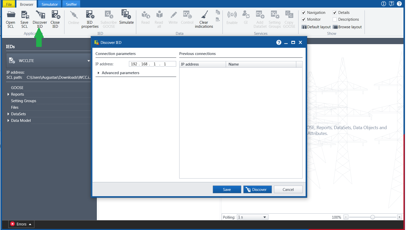
Fig. 9 Starting IED on IEDscout
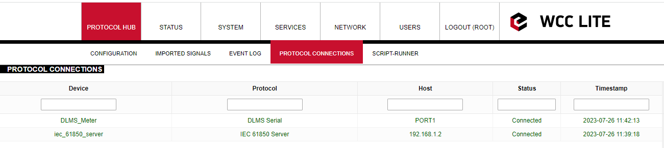
Fig. 10 Protocol connections
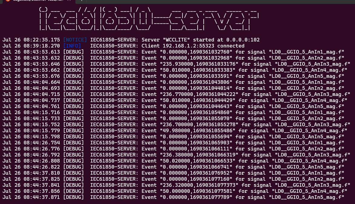
Fig. 11 Measurements from Meter linked to IEC61850 server signals
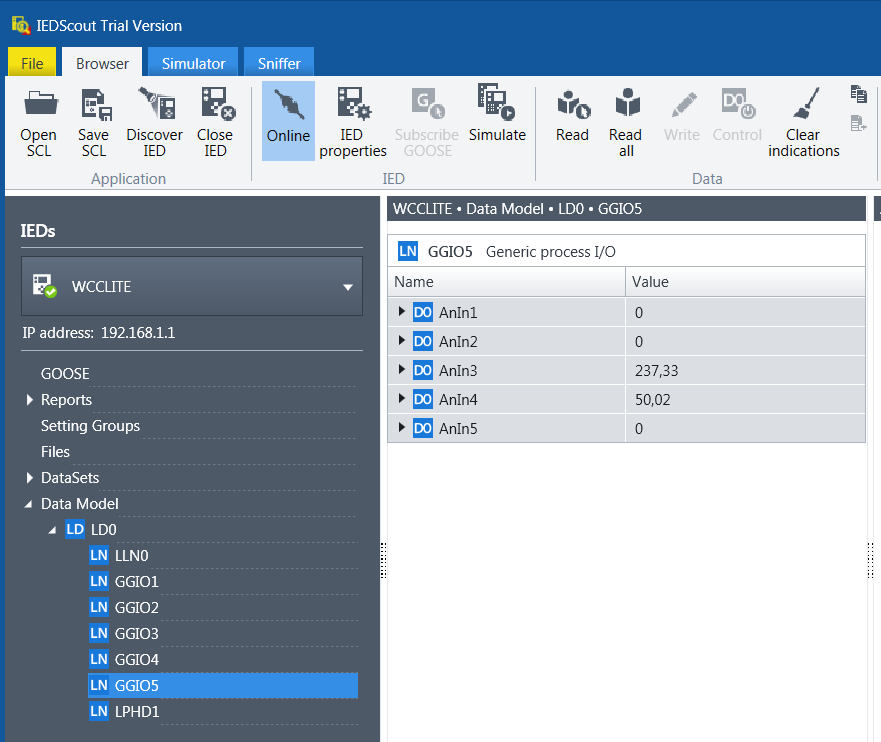
Fig. 12 Measurements appeared in IEDscout software
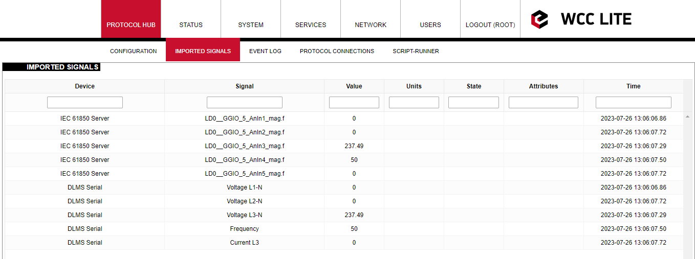
Fig. 13 Measurements represented in Wcc Lite WEB "Imported signals" tab.
Files used in this article:
1. ICD file: WCC.icd
2. Server Model file: WCC.cfg
3. Excel configuration file: WCC_full.xlsx
4. Excel Utility software: Excel Utility
5. Wcc Lite firmware: Wcc 1.7.0 RTU