DLMS Serial to IEC61850-server protocol conversion (WCC Lite FW: 1.10.0 or newer)
Description
This article explains how to configure the WCC Lite to convert data from a DLMS Serial protocol meter to an IEC 61850 server. The process includes device setup, signal mapping, server model creation, configuration upload, and validation through IEDscout.
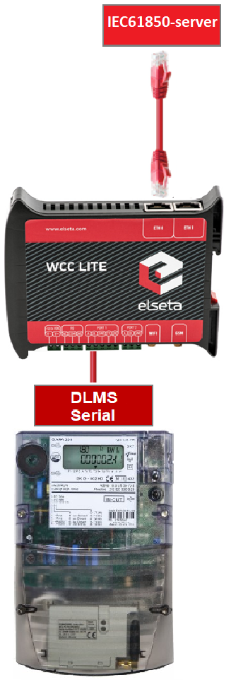
Fig 1. Connecting Meter with DLMS serial protocol to WCC Lite and IEC61850 server
Preparatiom
To begin, ensure that the WCC Lite is physically installed according to manufacturer's instructions. Connect your computer to the WCC Lite using an Ethernet cable via the ETH0 port. Log in using the default credentials and perform basic setup, including system name, network parameters, and user management. You can find additional assistance in related How to articles.
Excel configuration
Configuration is done using an Excel file containing two main sheets: Devices and Signals. In the Devices sheet, add a row for the DLMS meter. Specify its communication settings, including serial port parameters, protocol (DLMS), and authentication details. The serial number should also match the connected device.
Add required information for the connected Gama meter with DLMS Serial protocol:
| name | description | device_alias | protocol | serial_number | device | databits | stopbits | baudrate | parity |
| DLMS Serial | DLMS Serial | DLMS_Meter | DLMS | 2250259 | PORT1 | 8 | 1 | 4800 | none |
| flowcontrol | enable | auth | logical_address | address_size | client_address | type | mode |
| none | 1 | LOW | 1 | 2 | 32 | SN | DLMS-HDLC |
More information about DLMS protocol configuration is provided in DLMS/COSEM article.
Next, define a second row for the IEC 61850 server. Assign an alias and bind it to the 0.0.0.0 address. The model filename you enter here will later be matched to the server model file you generate. Define the IED name, logical device, access point, and port settings.
Add IEC 61850 server protocol required information:
| name | description | device_alias | protocol | bind_address |
| IEC 61850 Server | IEC 61850 Server | iec_61850_server | iec 61850 server | 0.0.0.0 |
| ied_name | access_point | port | auth |
host |
model_filename |
| WCCLITE | LD0 | 102 | NONE | 192.168.1.2 | WCC_test |
More information about IEC 61850 server protocol configuration is provided in IEC 61850 server article.
Configure signals (Excel "Signals_DLMS" sheet)
Move to the Signals sheets. You can split the signal definitions into separate sheets (e.g., SignalsDLMS and SignalsIEC61850) or place them all in a single one. For DLMS signals, enter OBIS codes that define what data to collect, such as voltages, frequency, and current. OBIS codes break down into six segments, each representing a specific aspect of the measured data—like media type, channel, physical quantity, and instantaneous value. In this example, voltage and frequency measurements are mapped using OBIS codes starting with 1, indicating electricity.
In the IEC 61850 signal sheet, link each IEC signal to its source signal from the DLMS device. This is done by referencing the alias of the source device and signal. You also need to define logical device instance, logical node class and instance, common data class, and data attributes. This mapping ensures that IEC 61850 server outputs correspond to the actual readings from the DLMS meter.
Add signal information for the connected meter with DLMS Serial protocol
(Excel SignalsDLMS sheet):
| signal_name | device_alias | signal_alias | obis_job |
| Voltage L1-N | DLMS_Meter | Voltage_L1-N | 1.0.32.7.0.255 |
| Voltage L2-N | DLMS_Meter | Voltage_L2-N | 1.0.52.7.0.255 |
| Voltage L3-N | DLMS_Meter | Voltage_L3-N | 1.0.72.7.0.255 |
| Frequency | DLMS_Meter | Frequency | 1.0.14.7.0.255 |
| Current L3 | DLMS_Meter | Current_L3 | 1.0.71.7.0.255 |
obis_job - Objects are identified with the help of OBIS (Object Identification System) codes.
- The first number of OBIS code defines the media (energy type) to which the metering is related. Nonmedia
related information is handled as abstract data. For example all obis_jobs in the table above starts with numbers 1 which stands for "Electricity related objects". - The second number defines the channel number, i.e. the number of the input of a metering
equipment having several inputs for the measurement of energy of the same or different types
(e.g. in data concentrators, registration units). Data from different sources can thus be
identified. The definitions for this value group are independent from the value of the first number. In all obis_jobs from the table above second number is set to zero which means that no channel is specified. - The third number defines the abstract or physical data items related to the information
source concerned, for example current, voltage, power, volume, temperature. The definitions
depend on the value of the first number. For example in obis_jobs from the table above number 72 means voltage L3 and number 14 means frequency. - The forth number defines types, or the result of the processing of physical quantities
identified with the numbers 1 and 3, according to various specific algorithms. The
algorithms can deliver energy and demand quantities as well as other physical quantities. In all obis_jobs from the table above forth number is set to 7 which stands for "Instantaneous value". - The value of the fifth number defines further processing or classification of quantities identified by numbers 1 to 4. In case of the first obis_job number 0 means that all harmonics of the signal along with its fundamental frequency are going to be taken into consideration.
- The value of the sixth number defines the storage of data, identified by numbers 1 to 5, according to
different billing periods. Where this is not relevant, this value group can be used for further
classification. In all obis_jobs from the table above last number is set to 255 which means that data is not used.
Add signals information for IEC 61850 server (Excel Signals_IEC61850 sheet):
| signal_name | device_alias | signal_alias | source_device_alias | source_signal_alias |
| LD0__GGIO_5_AnIn1_mag.f | iec_61850_server | LD0__GGIO_5_AnIn1_mag.f | DLMS_Meter | Voltage_L1-N |
| LD0__GGIO_5_AnIn2_mag.f | iec_61850_server | LD0__GGIO_5_AnIn2_mag.f | DLMS_Meter | Voltage_L2-N |
| LD0__GGIO_5_AnIn3_mag.f | iec_61850_server | LD0__GGIO_5_AnIn3_mag.f | DLMS_Meter | Voltage_L3-N |
| LD0__GGIO_5_AnIn4_mag.f | iec_61850_server | LD0__GGIO_5_AnIn4_mag.f | DLMS_Meter | Frequency |
| LD0__GGIO_5_AnIn5_mag.f | iec_61850_server | LD0__GGIO_5_AnIn5_mag.f | DLMS_Meter | Current_L3 |
| ld_instance | ln_class | ln_instance | cdc | data_object | da_fc | number_type | da_value | Log |
| LD0 | GGIO | 5 | MV | AnIn1 | MX | FLOAT32 | mag.f | 1 |
| LD0 | GGIO | 5 | MV | AnIn2 | MX | FLOAT32 | mag.f | 1 |
| LD0 | GGIO | 5 | MV | AnIn3 | MX | FLOAT32 | mag.f | 1 |
| LD0 | GGIO | 5 | MV | AnIn4 | MX | FLOAT32 | mag.f | 1 |
| LD0 | GGIO | 5 | MV | AnIn5 | MX | FLOAT32 | mag.f | 1 |
From the table above it can be seen that IEC 61850 server signals has source_device_alias and source_signal_alias in which device_alias and signal_alias of DLMS meter signals are described. That is how DLMS meter signals are linked to IEC61850 server signals, so the measurements of the DLMS meter could be transported to IEC 61850 server.
For more detailed DLMS protocol communication analysis Gurux DLMS Director application can be used.
Generating Server Model file for WCC Lite
For the IEC 61850 server to function, a model file is required. This file is based on an ICD file, which describes the server’s capability. The ICD file serves both for generating the server model and simulating client behavior with tools like IEDscout.
Open the WCC Excel Utility and choose the appropriate version from a drop-down menu in the Configuration tab (Fig. 3).
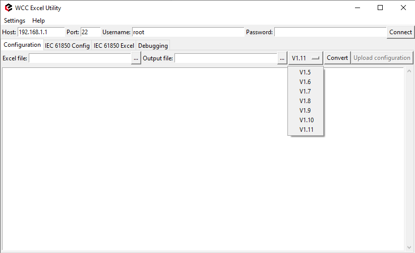 Fig. 3 Choosing the right version
Navigate to the IEC61850 Config tab, select the ICD file, and define the output directory for the server model file (Fig. 4). Ensure the filename matches the one specified in the Devices sheet. Press Convert to generate the model file. Then upload this file to the WCC Lite via the web interface (Fig. 5).
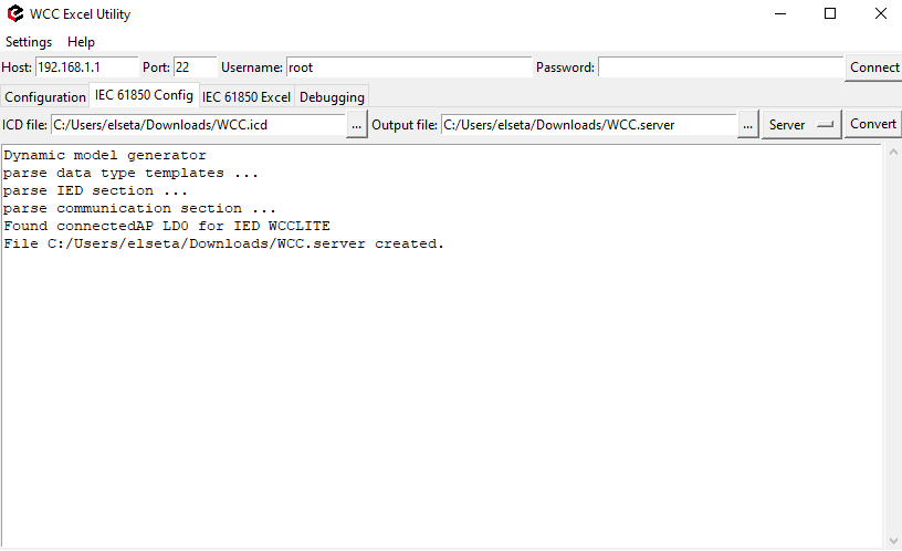 Fig. 4 Generating Server Model file
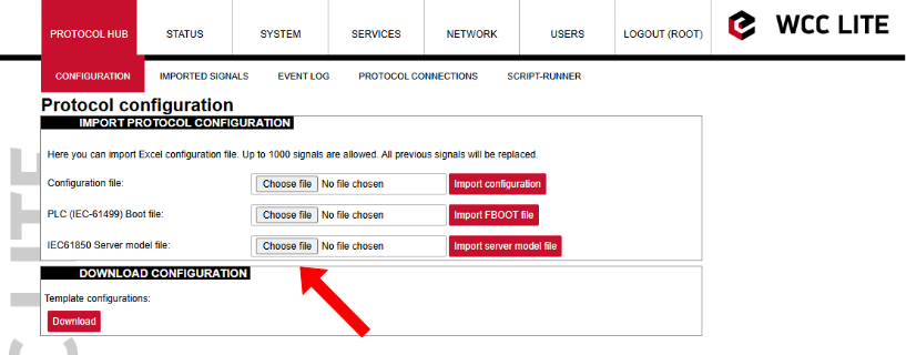
Fig. 5 Uploading IEC 61850 Server Model file to Wcc Lite WEB
Uploading Wcc Lite configuration
With the server model uploaded, confirm that the host IP address defined for the IEC 61850 server in the Excel file matches your computer’s IP address. You can set this manually in the network adapter settings to ensure proper communication.. This is shown in Fig. 6.
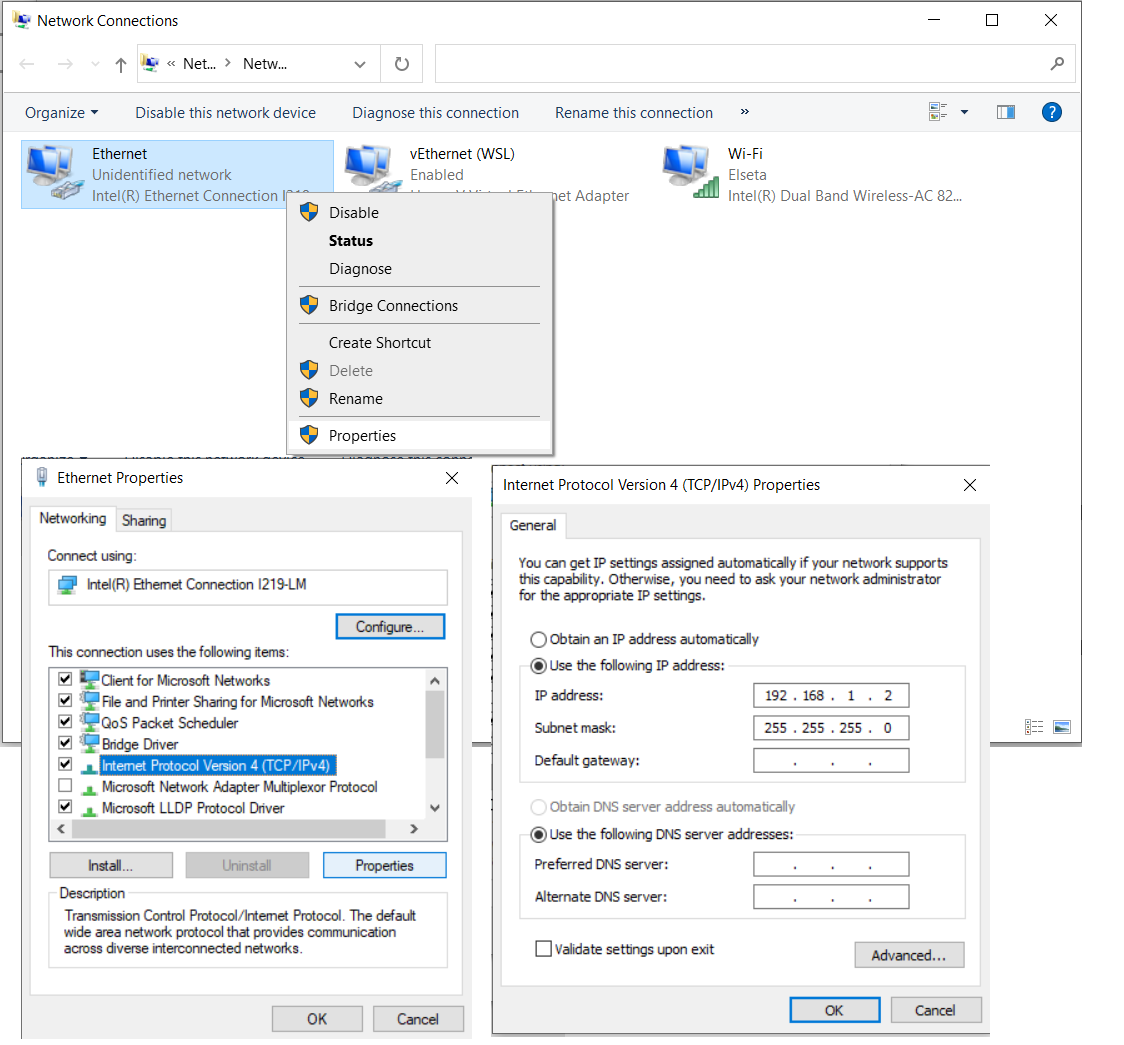
Fig. 6 Changing PC IP (TCP/IPv4) to match the Host IP in configuration
Return to the WCC Lite web interface and upload the Excel configuration file. Select the file and click "Import configuration" (Fig. 7) The import process may take a few minutes to complete.
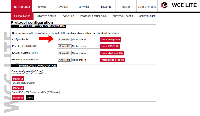
Fig. 7 Uploading Excel configuration to Wcc Lite.
Starting IEC 61850 server
To start the IEC 61850 server in debug mode, use a terminal emulator like PuTTY or a Linux subsystem terminal. This launches the service in debug mode, which outputs live data and connection logs. Following commands should be entered in the terminal window:
1. Connecting to Wcc Lite:
ssh root@192.168.1.12. Login: root Password: your Wcc Lite pasword
3. Stopping the IEC 61850 service:
/etc/init.d/iec61850-server stop4. Starting IEC61850 server in debugger mode:
iec61850-server -d7 -c /etc/iec61850-server/iec61850-server.json After these commands are executed, the IEC 61850 server is started, it is shown in Fig. 8.
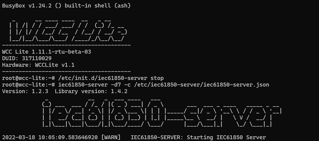 Fig. 8 Connecting to Wcc Lite through SSH and starting IEC61850 server
Connecting to Wcc Lite (server) on IEDscout (client)
To verify the system, open IEDscout or another IEC 61850 client simulator. Load the ICD file, discover the IED using the WCC Lite’s IP address, and if needed, press "Online" in IEDscout to establish the connection (Fig. 9). In the WCC Lite’s web interface, navigate to the protocol connections tab to confirm both DLMS and IEC 61850 are connected (Fig. 10) As measurements appear in the debugger terminal (Fig. 11), return to IEDscout and click "Read" to refresh the values (Fig. 12)
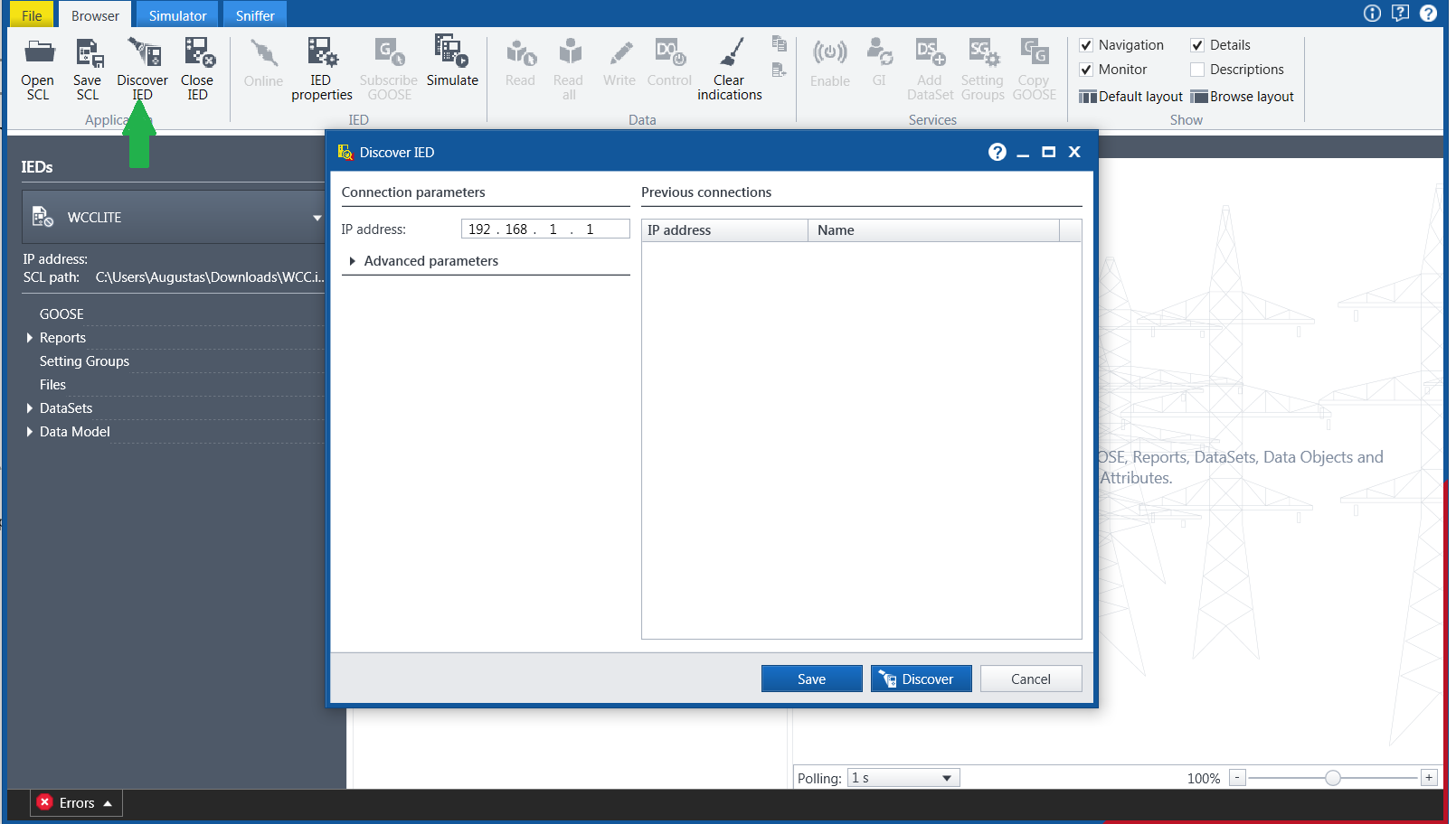 Fig. 9 Starting IED on IEDscout
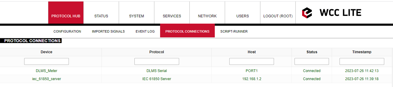
Fig. 10 Protocol connections
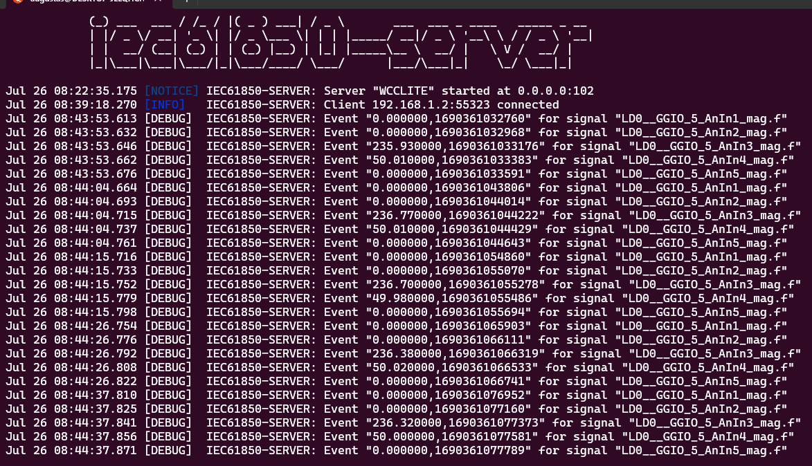
Fig. 11 Measurements from Meter linked to IEC61850 server signals
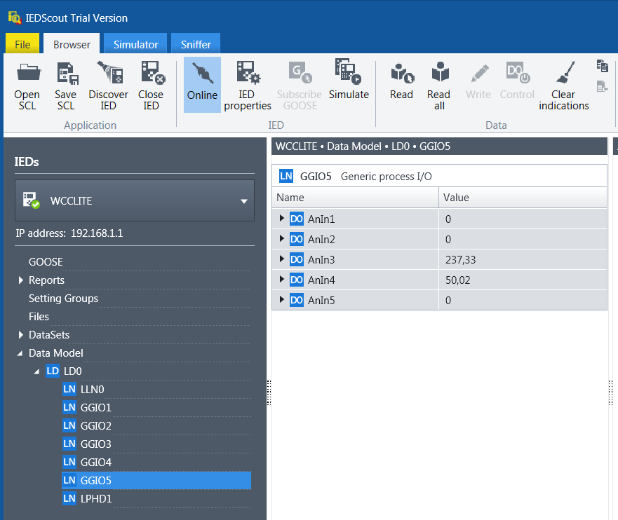
Fig. 12 Measurements appeared in IEDscout software
Finally, you can view all collected and converted data on the WCC Lite web interface under the Imported Signals tab. This confirms that your DLMS meter data is now available through the IEC 61850 server (Fig. 13)
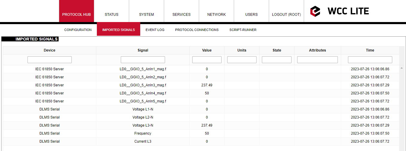
Fig. 13 Measurements represented in WCC Lite WEB Imported signals tab.
Files used in this article:
1. ICD file: WCC.icd
2. Server Model file: WCC.server
3. Excel configuration file: WCC.xlsx
4. Excel Utility software and firmware : Download