DLMS TCP to DNP3 protocol conversion
Setup
The article describes WCC Lite configuration steps to enable DLMS tcp protocol conversion to DNP3.
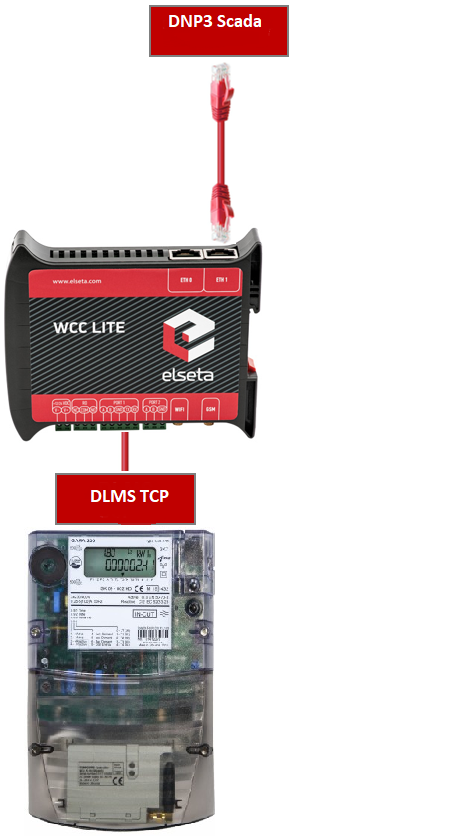
Fig 1. Connection scheme.
Before you begin, make sure you have completed all physical installation work according to the manufacturer's installation instructions.
Set up your computer and connect the Ethernet cable to the WCC Lite ETH0 port. Log in with default credentials and set up basic required settings (name, network, users, etc.). You can find configuration tutorials in How to articles.
To prepare the configuration, fill information in both the Devices and Signals sheets:
Configuring Devices
Add a connected Gama meter with the DLMS TCP protocol required information:
| name | description | device_alias | enable | protocol | serial_number | port |
| From Gama Meter | Elgama Gama 300 | GAMA300 | 1 | DLMS | 2393020 | 4059 |
| ip | logical_address | address_size | client_address | type | mode | auth | password |
| 192.168.1.2 | 1 | 2 | 32 | LN | DLMS-WRAPPER |
LOW |
00000002 |
More information concerning DLMS protocol configuration is provided in the DLMS/COSEM article.
Add the SCADA working on the DNP3 protocol required information:
| name | device_alias | enable | protocol | mode | host | bind_address |
| DNP3 SCADA system | DNP3_SCADA | 1 |
DNP3 TCP slave |
TCP | 192.168.1.215 | 0.0.0.0 |
|
port |
destination_address |
source_address |
unsol_classes |
| 20000 | 10 | 1 | 1,2,3 |
More information concerning DNP3 protocol configuration is provided in the DNP 3.0 Slave article.
Configuring Signals
Add connected meter measurements information.
| signal_name | device_alias | signal_alias | obis_job |
| Voltage L3-N | GAMA300 | L3_U | 1.0.72.7.0.255 |
| Frequency | GAMA300 | F | 1.0.14.7.0.255 |
| Current L3 | GAMA300 | L3-I | 1.0.71.7.0.255 |
| Absolute active instantaneous power | GAMA300 | P | 1.0.15.7.0.255 |
Obis_job - Objects are identified with the help of OBIS (Object Identification System) codes.
- The first number of the OBIS code defines the media (energy type) to which the metering is related. Non-media-related information is handled as abstract data. For example, both obis_jobs in the table above start with number 1, which stands for "Electricity related objects".
- The second number defines the channel number, i.e. the number of the input of a metering equipment having several inputs for the measurement of energy of the same or different types (e.g. in data concentrators, registration units). Data from different sources can thus be identified. The definitions for this value group are independent of the value of the first number. In both obis_jobs from the table above second number is set to zero, which means that no channel is specified.
- The third number defines the abstract or physical data items related to the information source concerned, for example, current, voltage, power, volume, temperature. The definitions depend on the value of the first number. For example, in obis_jobs from the table above, the number 72 means voltage L3, and the number 14 means frequency.
- The fourth number defines types, or the result of the processing of physical quantities identified with the numbers 1 and 3, according to various specific algorithms. The algorithms can deliver energy and demand quantities as well as other physical quantities. In both obis_jobs from the table above fourth number is set to 7, which stands for "Instantaneous value".
- The value of the fifth number defines further processing or classification of quantities identified by numbers 1 to 4. In case of the first obis_job number 0 means that all harmonics of the signal along with its fundamental frequency are going to be taken into consideration.
- The value of the sixth number defines the storage of data, identified by numbers 1 to 5, according to different billing periods. Where this is not relevant, this value group can be used for further classification. In both obis_jobs from the table above last number is set to 255, which means that the data is not used.
Add DNP3 Slave signals information:
| signal_name | device_alias | signal_alias | source_device_alias | source_signal_alias | enable |
| DNP3 SCADA V | DNP3_SCADA | DNP3_SCADA_V_L3_N | GAMA300 | L3_U | 1 |
| DNP3 SCADA F | DNP3_SCADA | DNP3_SCADA_Freq | GAMA300 | F | 1 |
| DNP3 SCADA A | DNP3_SCADA | DNP3_SCADA_A_L3 | GAMA300 | L3_I | 1 |
| DNP3 SCADA KW | DNP3_SCADA | DNP3_SCADA_P | GAMA300 | P | 1 |
| index | signal_type | static_variation | event_variation | class_num |
| 1 | analog | 1 | 3 | 2 |
| 2 | analog | 1 | 3 | 2 |
| 3 | analog | 1 | 3 | 2 |
| 4 | analog | 1 | 3 | 2 |
For more detailed DLMS protocol communication analysis Gurux DLMS Director application can be used.
Uploading the Configuration
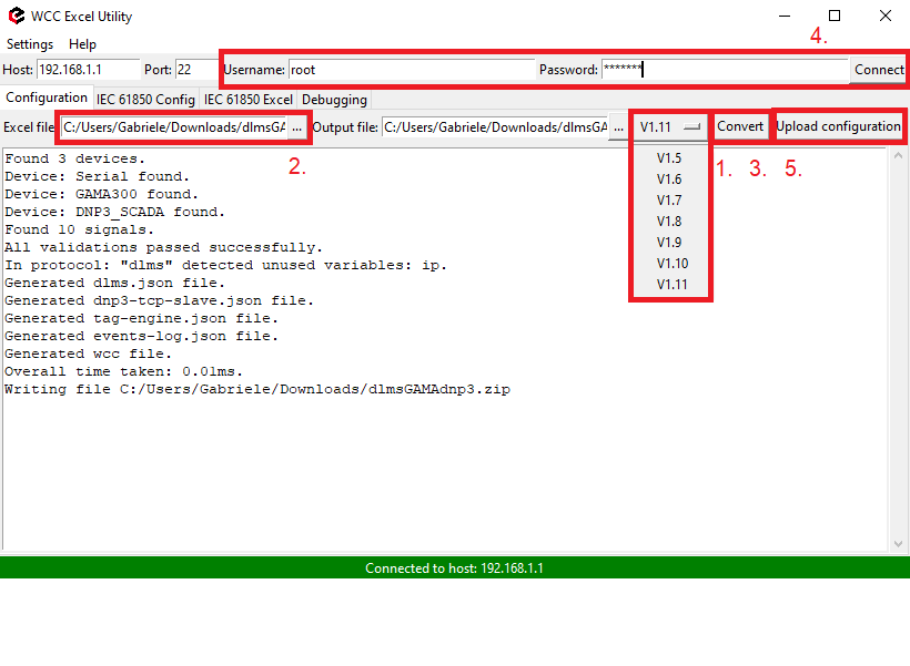
After configuring all devices and signals, follow these steps to check and upload the configuration using the WCC Excel Utility:
- Download and run WCC Excel Utility.
- Select the firmware version from the drop-down menu.
- Select the Excel file from your computer and click Convert.
- Check if no events in red color occur. If so, edit the Excel file according to the event text and repeat Step 2.
- Enter the Host and credentials of WCC Lite, click connect and then Upload configuration.
Another method to upload the configuration is via the web interface:
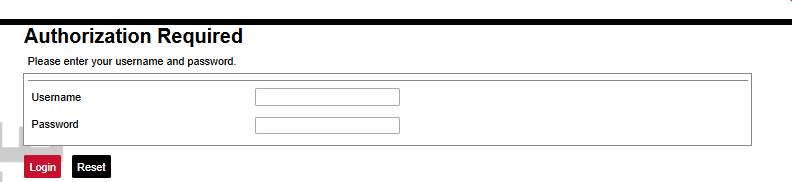
- Access the WCC Lite interface via your browser. The default IP address is 192.168.1.1. Enter credentials:
- Upload the Excel configuration:
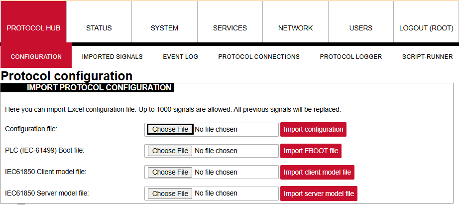
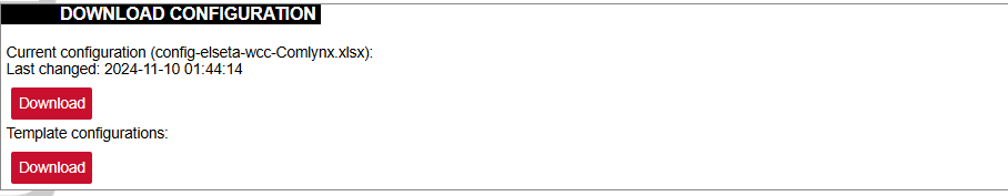
- After a successful upload, the configuration will appear under the DOWNLOAD CONFIGURATION tab:
- If any errors occur during the upload, follow the error messages, fix them according to Excel utility guidelines.


