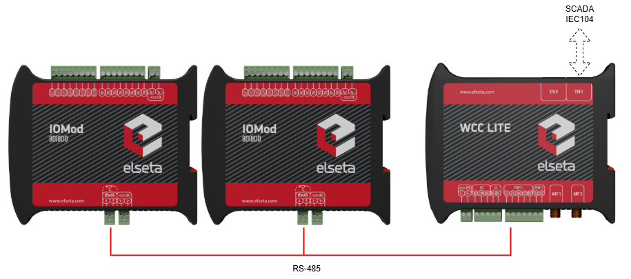
Connecting 2x 8DI8DO IOMod to the WCC Lite
Description
This article describes connecting and configuring two IOMOD 8DI8DO to the WCC Lite PORT1.
Each IOMod must be configured to match the Excel configuration. If using the template configuration, default parameters should be applied to the IOMod. IOMODs with firmware version 2 are configured using the IOMod utility application either via the USB port on the device's front panel or via the RS-485. Refer to the IOMod 8DI8DO user manual
Each IOMOD has its own set of parameters that can be adjusted without modifying the WCC Lite configuration. These can be accessed through the device's configuration menu.
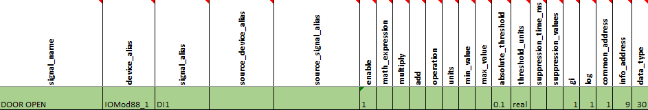
If you are creating a custom configuration, especially when multiple devices of the same type are connected to the same port, make sure that the Device_alias values are unique for each device in the Devices sheet. Link address values must be different. Additionally, in the Signals sheet, Device_alias and Signal_alias combinations must not be duplicated across different devices.
Uploading configuration
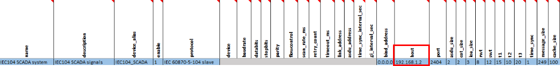
The configuration can be modified to suit your specific needs. You can use the example provided above (2x_8DI8DO.xlsx) as a reference. If different IEC104 slave settings are required, they can be modified in the Excel configuration. For example, you can adjust settings such as info_address or data_type to match the desired behavior of the IEC104 slave. To test this example, specify your computer's IP address in the IEC104 slave’s host column in the Excel file.
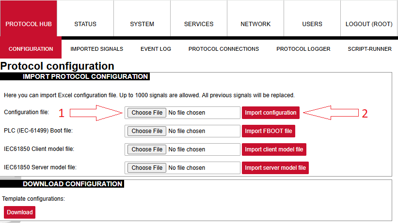
Once the configuration is ready, upload it to WCC Lite via Configuration --> Choose file --> Import configuration.
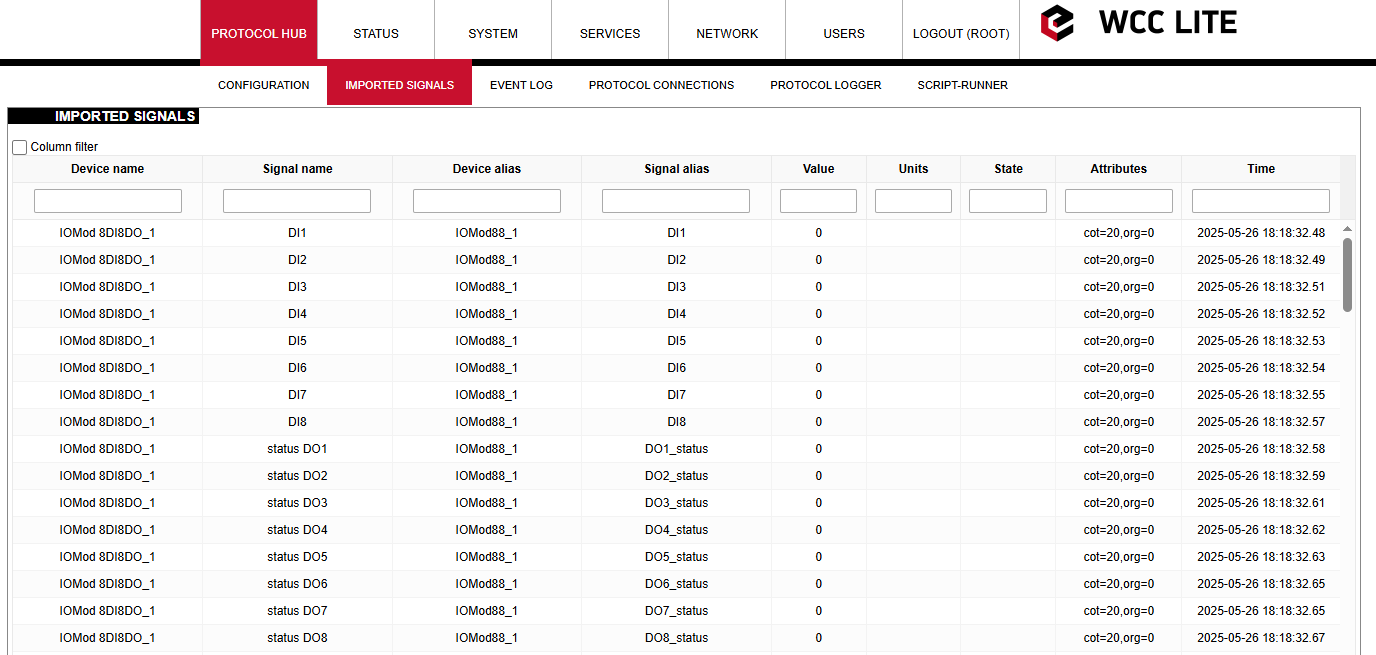
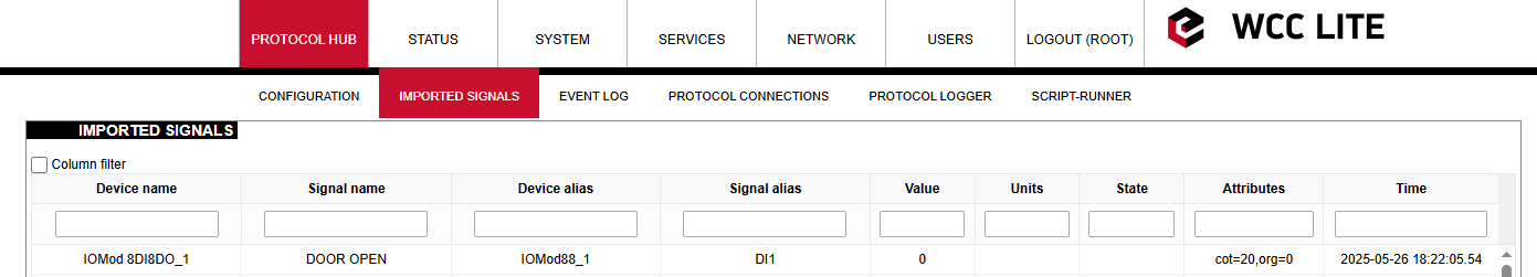
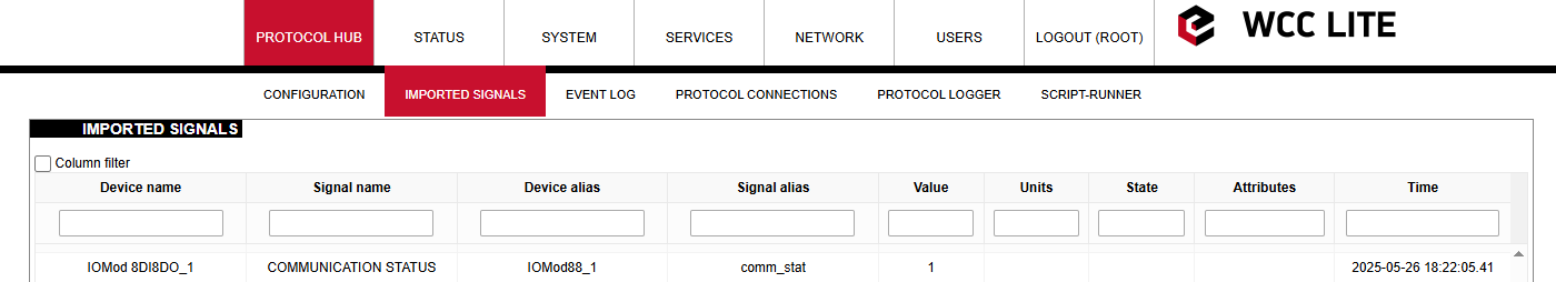
After the upload completes and no errors are detected, go to Protocol Hub --> Imported signals to verify that all signals have been successfully imported.
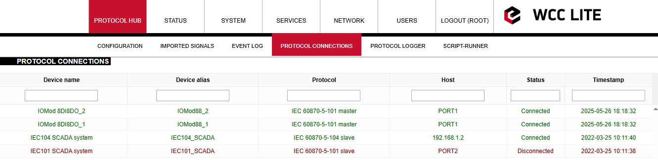
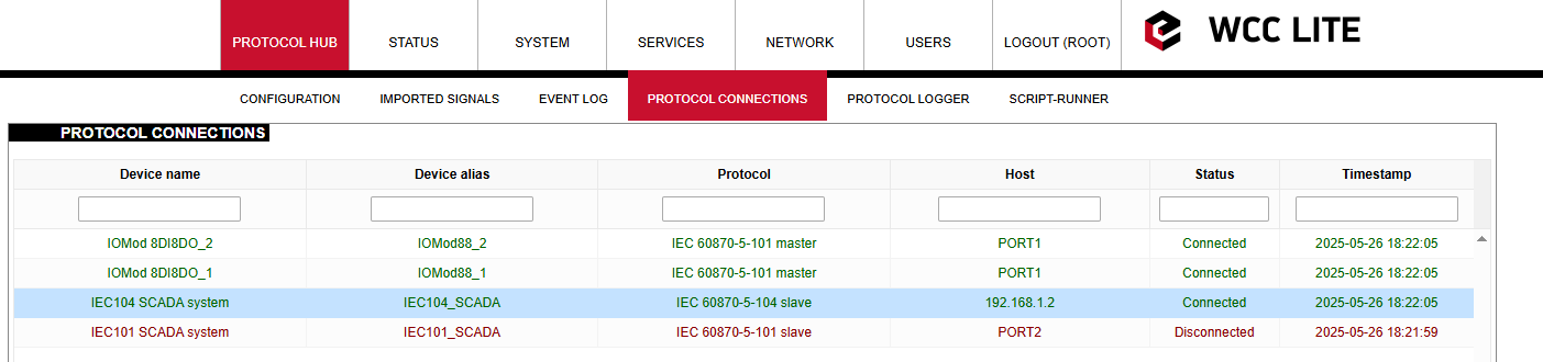
Before proceeding, check the protocol connections to confirm that both IOMOD 8DI8DO devices are connected to WCC Lite via PORT1. Open the Protocol Connections section to view all connected slave and master protocol devices.
You can rename signal names according to your preferences.
In every signals sheet, there is a signal named COMMUNICATION STATUS. This signal indicates whether the WCC Lite has established a connection with the device.
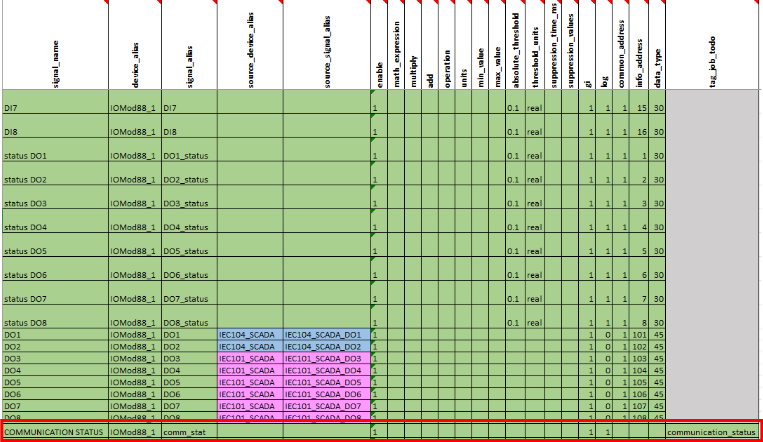
If everything is connected correctly and the service is running, the COMMUNICATION STATUS should display a value of 1. If not connected, it will display a value of 2.
If the IOMOD needs to be connected to another port, you can change the configuration by updating the Device value in the Devices sheet from PORT1 to PORT2.
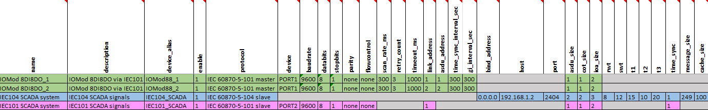
Please note that each port on the WCC Lite can only run a single protocol. Mixing different protocols on the same port is not supported. In addition, each device must have unique values for parameters such as ID, link address, and ASDU address.
Simulating SCADA via Vinci software
After uploading the Excel configuration, you can simulate a SCADA connection using Vinci software. To simulate an IEC 104 slave, select the IEC 60870-5-104 protocol, choose Master (Client) mode, and press Start. In the Settings tab, make sure the Structure (COT, ASDU, and IOA size), Timeouts, and Windows values match those defined in the Excel configuration.
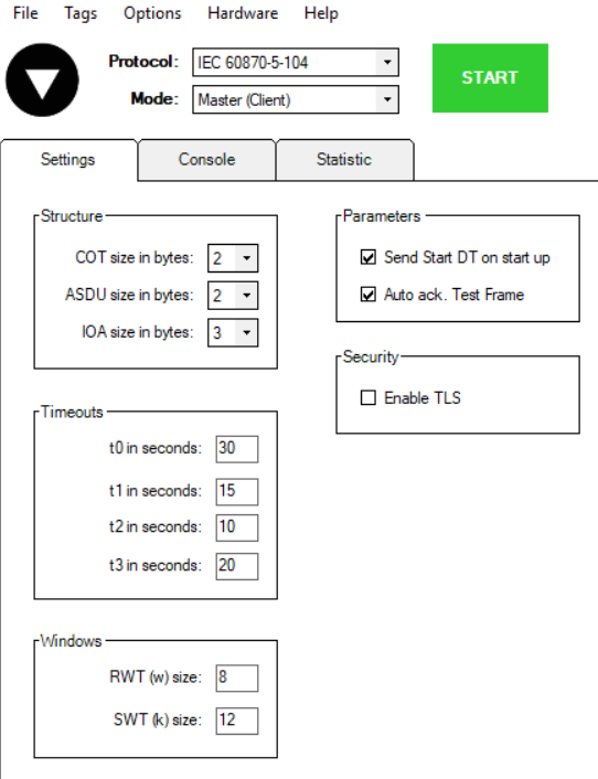
Set the correct IP address and port at the top of the Vinci window. The default IEC104 port is 2404. The IP address should match the IP of your WCC Lite device (by default, 192.168.1.1 if connected directly to your computer via Ethernet).

After clicking Start, open the Protocol Connections tab again to verify that the IEC104 slave is connected.
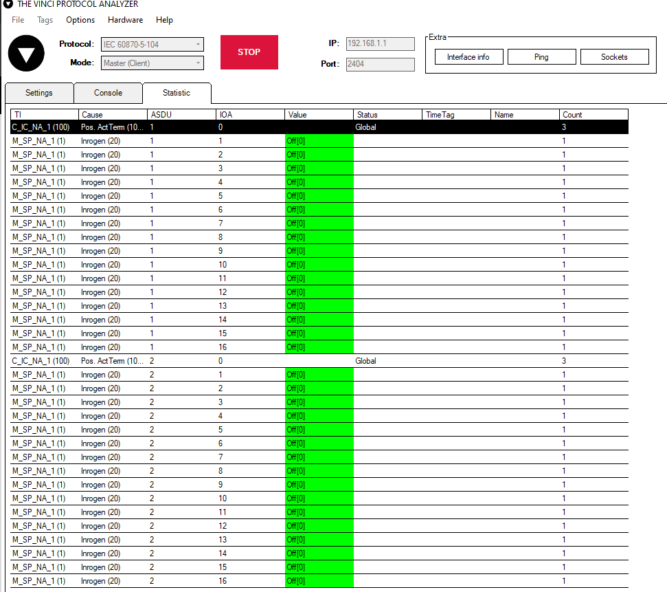
Once the IEC104 slave is connected, send a General Interrogation (GI) command. If everything is working correctly, the Statistics tab in Vinci should begin to display live data.
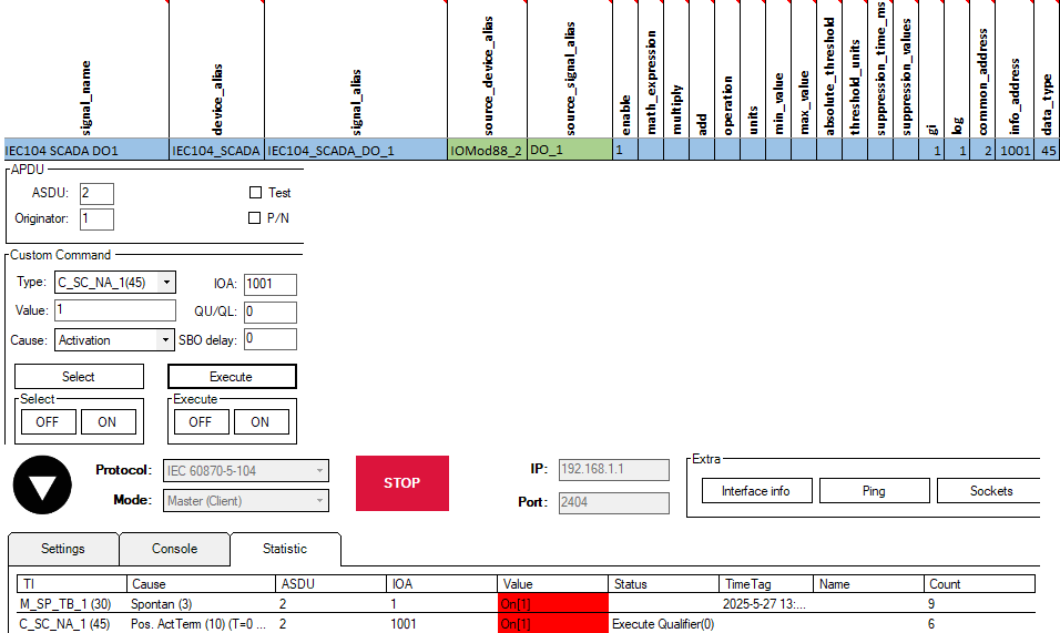
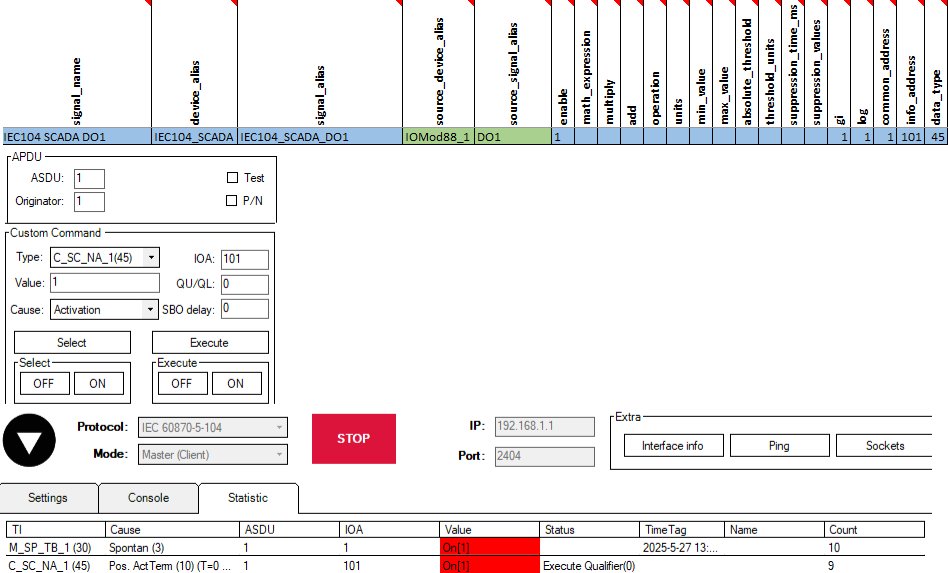
To test further, let's activate the first digital output (DO1) on both IOMODs. To do this, we will send a type 45 command (C_SC_NA_1).
In the Excel configuration, under the sheet Signals_IEC104, we specified that to activate the output on the first IOMOD, the command must be sent with the following parameters:
ASDU (common_address) = 1, IOA (info_address) = 101, type (data_type) = 45.
For testing the second IOMOD, we assigned DO1 to IOA = 1001. The procedure remains the same—send a command with type = 45, this time using ASDU = 2, IOA = 1001.