IOMOD 8DI8DO User Manual
1. Introduction
The IOMod 8DI8DO is a compact, standalone digital input and output controller compatible with Modbus RTU, IEC 60870-5-101, and IEC 60870-5-103 protocols. It is designed for industrial applications that require digital signaling and robust communication. The IOMod is an ideal solution for process monitoring and control in remote locations and integrates seamlessly with any SCADA system.
1.1 Features
- 8 digital inputs;
- 8 digital open-collector outputs;
- Galvanically isolated inputs and outputs for enhanced safety and reliability;
- Configurable using the IOMod utility app for a user-friendly setup;
- RS-485 communication for robust data exchange;
- LED indicators for input/ output status, data transmission (Rx), and data reception (Tx);
- Compact case with a removable transparent front panel;
- DIN rail mounting for seamless integration into industrial systems.
1.2 Block diagram
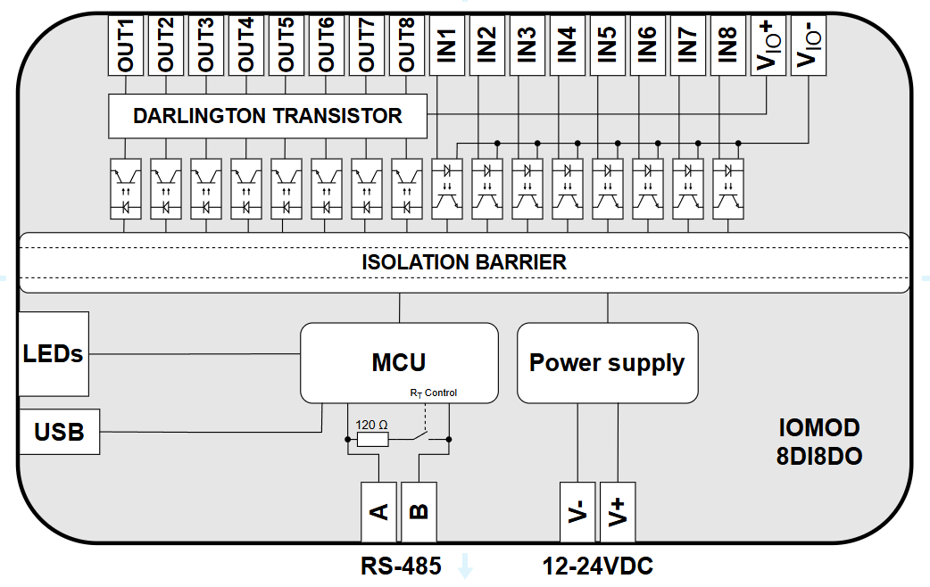
Fig. 1.2.1 IOMod 8DI8DO internal structure and block diagram
2. Hardware data
2.1 Mechanical drawings
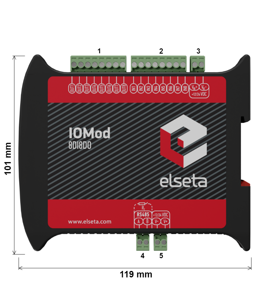 Fig. 2.1.1 IOMod 8DI8DO side view with dimensions and terminal descriptions.
1 - digital outputs; 2 - digital inputs; 3 - input/output power supply;
4 - RS-485 interface; 5 - Power supply
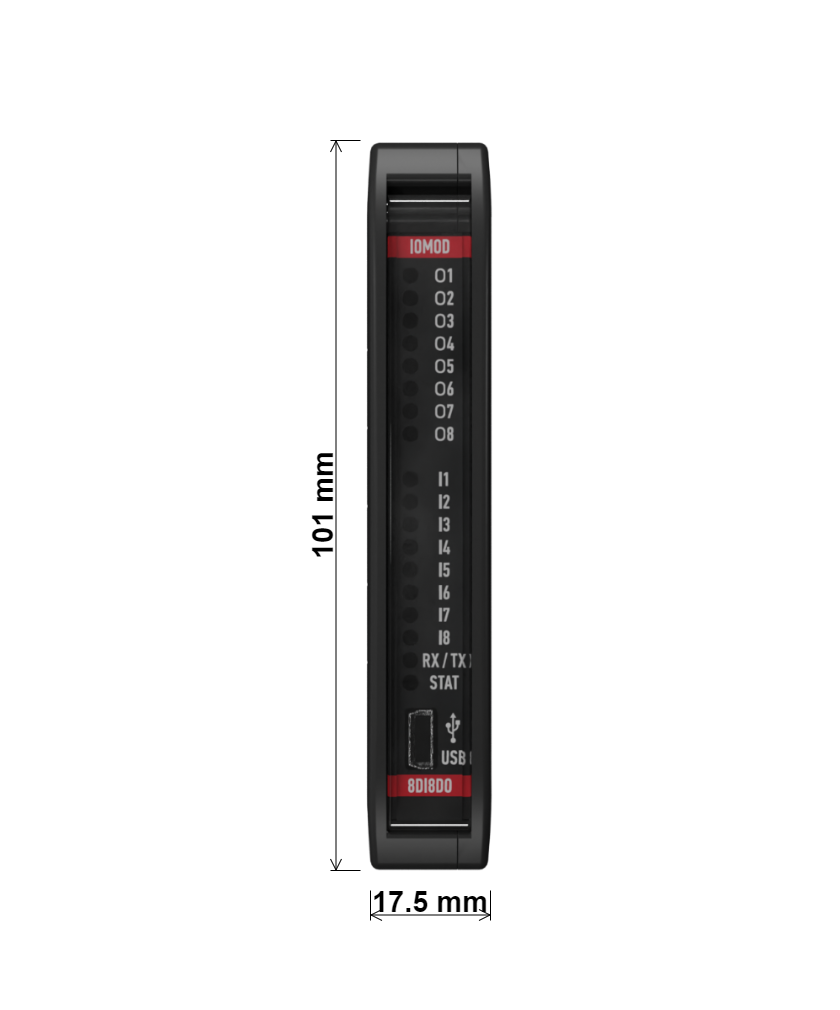
Fig. 2.1.2 IOMod 8DI8DO front view with dimensions
2.2 Terminal connections
IOMod 8DI8DO has 22 terminals, which are depicted below:
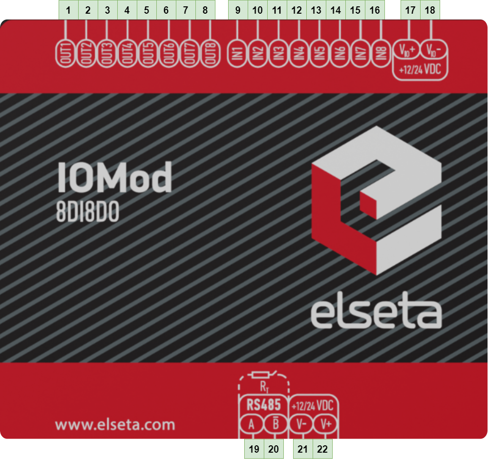 Fig. 2.2.1 IOMod 8DI8DO terminals diagram
The description of each terminal can be found in the table below:
Table 2.2.1 Terminal specifications
|
Terminal number |
Terminal name |
Description |
|
1 |
DO1 |
Digital outputs |
|
2 |
DO2 | |
|
3 |
DO3 | |
|
4 |
DO4 | |
|
5 |
DO5 | |
|
6 |
DO6 | |
|
7 |
DO7 | |
|
8 |
DO8 | |
|
9 |
DI1 |
Digital inputs |
|
10 |
DI2 | |
|
11 |
DI3 | |
|
12 |
DI4 | |
|
13 |
DI5 | |
|
14 |
DI6 | |
|
15 |
DI7 | |
|
16 |
DI8 | |
|
17 |
VIO+ | Input/output positive power source |
|
18 |
VIO- | Input/output negative power source |
|
19 |
A | RS485 input |
|
20 |
B | RS485 input |
|
21 |
V- | Power source input |
|
22 |
V+ | Power source input |
2.3 Status indication
IOMod 8DI8DO has LEDs (Fig. 2.3.1), which are used to indicate outputs, inputs, communication and power statuses.
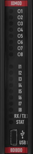
Fig. 2.3.1 IOMod 8DI8DO LEDs physical location
The description of each IOMod 8DI8DO LED can be found in the table below:
Table 2.3.1. Description of LEDs
| Name |
LED color |
Description |
| O1- O8 |
🟠 (orange) |
Indicates output status |
| I1- I8 |
🟠 (orange) |
Indicates input status |
|
RX/TX |
🟢 (green) |
A flashing green light indicates active communication via the RS-485 interface |
|
STAT |
🔴 (red) |
The power source is connected only to the power supply input of the device |
|
🟢 (green) |
Power source is connected to both power supply input of the device and the input/output power supply |
|
|
🔵 (blue) |
IOMod 8DI8DO is connected to an external device via a USB mini cable |
3. Technical information
Table 3.1.1 Technical specifications
| System | ||
| Dimensions | 101 x 119 x 17.5 mm |
|
| Case | ABS, black |
|
| Working environment | Indoor |
|
| Operating temperature | -40°C ... +85°C |
|
| Recommended operating conditions | 5–60°C and 20–80%RH |
|
| Configuration |
USB, RS485 |
|
| Firmware upgrade | USB, RS485 |
|
| Electrical specifications |
||
|
Outputs |
open collector outputs |
9–33 VDC (@current < 400 mA shared across all 8 outputs) |
|
Isolation |
8 X 3 kV(RMS) |
|
|
Inputs |
Nominal input voltage range |
6–33 VDC (@current 1.3 mA - 16 mA) |
|
Isolation |
8 X 3 kV(RMS) |
|
| Power |
||
| Power Supply | 9–33 VDC (full range) |
|
| Current consumption | 40 mA @ 12 VDC, 20 mA @ 24 VDC |
|
4. Mounting and installation
4.1 Connection Diagrams
In this chapter the various options of connecting the device to systems are discussed.
4.1.1 Digital inputs
The typical application of IOMod 8DI8DO inputs is shown in Fig. 4.1.1.1. When the default configuration for the inputs is applied, the user will observe inputs connected to +12/24 V as “high” or in state “1,” and the input status LED will illuminate.
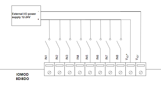
Fig. 4.1.1.1 Input configuration example
4.1.2 Digital outputs
The outputs are the sink type (NPN), meaning they provide a path to ground. The load is connected between the output and the positive voltage. When an output is active, current flows from the power supply through the load to ground, the output state becomes "high" (1), and the corresponding status LED illuminates. A typical output application is shown in Fig. 4.1.2.1.
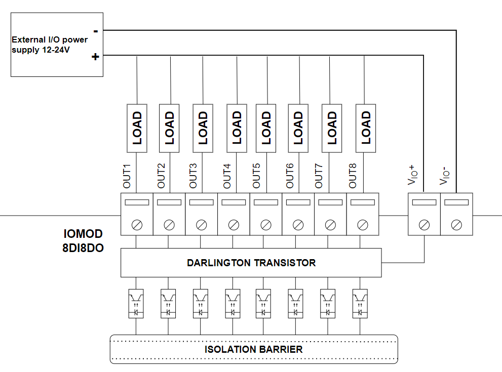
Fig. 4.1.2.1. Output configuration example
4.2 Power supply
IOMod 8DI8DO needs to be powered by a 9–33 V power source. IOMod power supply inputs are located next to RS485 interface inputs (Fig. 4.2.1)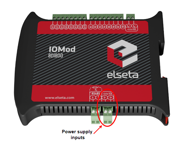
Fig. 4.2.1 Power supply input physical location
4.3 USB connection
The IOMod 8DI8DO device features a USB-mini connection port, primarily used to establish a physical connection between the IOMod and a PC. By selecting the USB interface and the correct communication port in the IOMod Utility (see Fig. 4.3.1), the user can connect to the IOMod to control its parameters and monitor data.
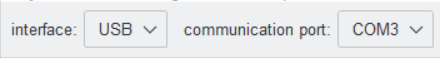
Fig. 4.3.1 IOMod Utility interface and communication port parameters
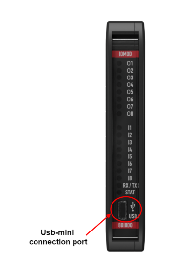
Fig. 4.3.2 IOMod 8DI8DO USB connection port physical location
5. Parametrization
5.1 IOMod 8DI8DO common settings
5.1.1 Input Inversion
If the user wants the input status to display as "ON" when the input signal is in a low state, the inputs can be logically inverted via the IOMod utility application under the IOMod settings tab (Fig. 5.1.1.1).
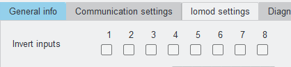
Fig. 5.1.1.1 Input inversion on IOMod utility app
When input inversion is enabled, the input state will show 1 (ON) when no signal is connected and will change to 0 (OFF) when the input is activated.
Note: The input indication LEDs are not affected by this inversion and will continue to reflect the actual signal state.
Example:
Input 2 has input inversion enabled in the IOMod Utility application. Both inputs, IN1 and IN2, are physically activated, and the LEDs on the IOMod are lit for both inputs. However, on the SCADA system:
- IN1 will be displayed as "1" (ON).
- IN2 will be displayed as "0" (OFF) due to the input inversion setting.
5.1.2 Output Inversion
If the user wants the output status to display as "ON" when the output signal is in a low state, the outputs can be physically inverted via the IOMod utility application under the IOMod settings tab (Fig. 5.2.4).
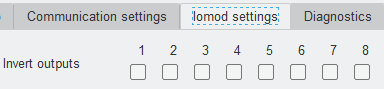
Fig. 5.1.2.1 Output inversion on IOMod utility app
When output inversion is enabled, the output state will show 1 (ON) when the output is not activated and will change to 0 (OFF) when the output is activated.
Example:
In the their initial state, before sending any activation commands the output signal of all outputs are low and their LEDs are not lit. Setting output inversion for the second output in the IOMod Utility application sets its output signal state to high and activates its LED. However if we would read the status of the second output with a master device, we would not notice the change in its status though it was physically activated after inversion. The read status is going to be inactive. Sending activation command to the second output sets its output signal to low state and tuns off its LED. However read status is going to be active.
5.1.3 Input filter
The filter time specifies the duration for which the input must remain stable before a status change is transmitted. The time interval is set in milliseconds. The default interval is 50 ms.
Input filter time can be set in the IOMod utility application under the IOMod settings tab (Fig. 5.1.3.1).
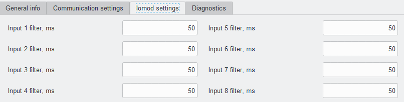
Fig. 5.1.3.1 Input filter on IOMod utility application
5.2 Device settings for Modbus protocol
All device parameters can be changed with the IOMod utility under the IOMod settings tab (Fig. 5.2.3). For the Modbus protocol user can set input, output inversion and input, output filter.
 Fig. 5.2.3 IOMod settings tab on utility application
5.2.1 Output pulse time
The output pulse time defines how long an output remains active after receiving a command. It is set in milliseconds. The default value is 0 ms, meaning the pulse function is disabled.
Output pulse time can be set in the IOMod utility application under the IOMod settings tab (Fig. 5.2.1.1).
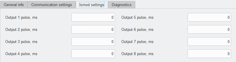
Fig. 5.2.1.1 Output pulse time on IOMod utility app
5.3 Device settings for IEC 60870-5-101 protocol
The device parameters can be changed with the IOMod utility application under the IOMod settings tab. For the IEC 60870-5-101 protocol user can enable: input and output grouping, swap grouped inputs and outputs, invert inputs and outputs, filter inputs and set output pulse time.
5.3.1 Input Grouping
Certain applications require combining two inputs into a one double-point (DPI) input. This is done by grouping two neighboring pins, where the first pin in the pair must be odd-numbered. When grouped, the second pin in the pair is not used anymore – all requests to this pin will generate an error.
Example:
- Valid: IN1 and IN2 (IN2 becomes unused).
- Invalid: IN2 and IN3.
Input grouping settings can be enabled via the IOMod utility application under the IOMod settings tab (Fig. 5.3.1.1).
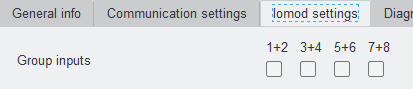
Fig. 5.3.1.1 Input grouping settings on IOMod utility app
5.3.1.1 Swap grouped inputs
Grouped inputs are referred to as Double Point Information (DPI) inputs. DPI signals consist of two bits of information, allowing for four possible states, thus providing more detail compared to SPI. For example, the INDETERMINATE state might indicate that part of the equipment is turned off or that a mechanical component responsible for switching is stuck between states. The ERROR state could signify that both contacts are connected, possibly indicating a short circuit in the equipment.
Table 5.3.1.1.1 Double-point states
| Value | State |
| 00 | indeterminate |
| 01 | off |
| 10 | on |
| 11 | error |
Practical usage example of the Swap Grouped Inputs setting: In a typical configuration, an active IN1 indicates the OFF position, and an active IN2 indicates the ON position. However, if a technician accidentally mismatches the cables during installation, resulting in IN1 indicating ON and IN2 indicating OFF, the Swap Grouped Inputs setting allows the positions of the inputs to be swapped without requiring any physical reconnection of the cables.
Swap grouped inputs can be enabled via the IOMod utility application under the IOMod settings tab (Fig. 5.3.1.1.1).
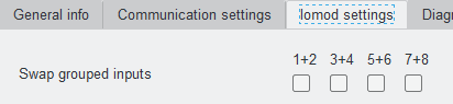
Fig. 5.3.1.1.1 Swap grouped inputs setting on the IOMod utility application
5.3.2 Output grouping
Certain applications require combining two outputs into a one double-point (DPI) output. This is done by grouping two neighboring pins, where the first pin in the pair must be odd-numbered. When grouped, the second pin in the pair is not used anymore – all requests to this pin will generate an error.
Example:
- Valid: DO1 and DO2 (DO2 becomes unused).
- Invalid: DO2 and DO3.
46-type command (C_DC_NA_1, double-point command) must be used to activate DPI outputs. When outputs are grouped, only short and long pulse commands are executed. The short pulse is sent with qualifier 1 (QU/QL = 1), while a long pulse is sent with qualifier 2 (QU/QL = 2). Each output pair is assigned to an Information Object Address (IOA):
- 101: DO1 and DO2 pair
- 103: DO3 and DO4 pair
- 105: DO5 and DO6 pair
- 107: DO7 and DO8 pair
Output grouping can be enabled via the IOMod utility application under the IOMod settings tab (Fig. 5.3.2.1).
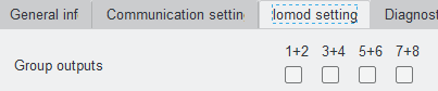 Fig. 5.3.2.1 Group outputs settings
5.3.2.1 Swap grouped outputs
If desired, output groups can be swapped. Grouped Output Swapping allows you to exchange the positions of the grouped pins. After swapping, the even-numbered pin can become the first pin in the pair, and the odd-numbered pin follows. For instance, if DO1 and DO2 are grouped, you can swap their positions so that DO2 becomes the first in the pair.
Swap grouped outputs can be enabled via the IOMod utility application under the IOMod settings tab (Fig. 5.3.2.1).
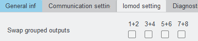 Fig. 5.3.2.1 Swap grouped outputs settings
5.3.3 Output short and long pulses
Users can configure outputs to be pulse-controlled – it means that the output will be turned on for the configured amount of time. When this time runs out, output is turned off. This is useful when pulse toggle relays are used. The output pulse is independent of the output grouping option and can be used on both grouped and ungrouped outputs.
The IEC101 protocol has settings for long and short pulse commands. Unlike the Modbus RTU protocol, the IEC-60870-5-101 protocol offers options for short and long pulses. A short pulse is typically sent with qualifier 1 (QU/QL = 1), while a long pulse is usually sent with qualifier 2 (QU/QL = 2). Short and long pulse interval is set in milliseconds.
Output short and long pulse intervals can be set via the IOMod utility application under the IOMod settings tab (Fig. 5.3.3.1).
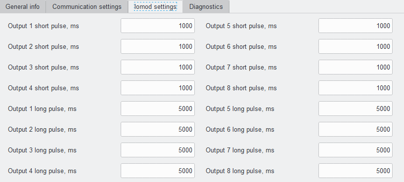 Fig. 5.3.3.1 Short and long output pulse settings
5.3.4 Select Before Operate (SBO)
SBO ensures that an output action (such as turning a relay on or off) is carried out only after the output has been explicitly selected. This helps prevent accidental or unauthorized operations, ensuring that the operator's intent is confirmed before acting. For example, the user wants to turn on DO1. First, they issue a select command to DO1. After the selection is acknowledged, the user sends an execute command to activate the DO1 output. If the command is successful, the output is turned on. If there’s an issue, a negative acknowledgement (NACK) will be sent, and no change will occur. There is also an output SBO time option, which ensures that the operation is not immediately executed but is instead delayed to allow for confirmation or review before the operation is carried out.
Select Before Operate can be enabled via the IOMod utility application under the IOMod settings tab (Fig. 5.3.4.1).
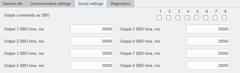
Fig. 5.3.4.1 Select before operate settings
5.4 Device settings for IEC 60870-5-103 protocol
The device parameters can be changed with the IOMod utility application under the IOMod settings tab. For the IEC 60870-5-103 protocol user can enable: input/output grouping, swap grouped inputs/outputs, invert inputs/outputs, filter inputs and set output pulse time.
5.4.1 Input Grouping
Certain applications require combining two inputs into a one double-point (DPI) input. This is done by grouping two neighboring pins, where the first pin in the pair must be odd-numbered. When grouped, the second pin in the pair is not used anymore – all requests to this pin will generate an error.
Example: IN1 and IN2 can be grouped, but after grouping, IN2 is disabled. IN2 and IN3 cannot be grouped, but IN3 and IN4 can be grouped, disabling IN4.
Input grouping can be achieved via the IOMod utility application under the IOMod settings tab (Fig. 5.4.1.1).
Fig. 5.4.1.1 Input grouping settings on IOMod utility app
5.4.1.1 Swap grouped inputs
Grouped inputs are referred to as Double Point Information (DPI). DPI signals consist of two bits of information, allowing for four possible states, thus providing more detail compared to single-point inputs. For example, the INDETERMINATE state might indicate that part of the equipment is turned off or that a mechanical component responsible for switching is stuck between states. The ERROR state could signify that both contacts are connected, possibly indicating a short circuit in the equipment.
Table 5.4.1.1 Double-point states
| Value | State |
| 00 | indeterminate |
| 01 | off |
| 10 | on |
| 11 | error |
Practical usage example of the Swap Grouped Inputs setting: In a typical configuration, an active IN1 indicates the OFF position, and an active IN2 indicates the ON position. However, if a technician accidentally mismatches the cables during installation, resulting in IN1 indicating ON and IN2 indicating OFF, the Swap Grouped Inputs setting allows the positions of the inputs to be swapped without requiring any physical reconnection of the cables.
Swap grouped inputs can be enabled via the IOMod utility application under the IOMod settings tab (Fig. 5.4.1.1).
Fig. 5.4.1.1 Swap grouped inputs setting on the IOMod utility application
5.4.2 Output grouping
Certain applications require combining two outputs into a one double-point (DPI) output. This is done by grouping two neighboring pins, where the first pin in the pair must be odd-numbered. When grouped, the second pin in the pair is not used anymore – all requests to this pin will generate an error.
Example:
- Valid: DO1 and DO2 (DO2 becomes unused).
- Invalid: DO2 and DO3.
The function type of the output commands has to be 254. Info number represents the number of output pins (1-8 accordingly).
- 1: DO1 and DO2 pair
- 3: DO3 and DO4 pair
- 5: DO5 and DO6 pair
- 7: DO7 and DO8 pair
Output grouping can be enabled via the IOMod utility application under the IOMod settings tab (Fig. 5.4.2.1).
Fig. 5.4.2.1 Group outputs settings
5.4.2.1 Swap grouped outputs
If desired, output groups can be swapped. Grouped Output Swapping allows you to exchange the positions of the grouped pins. After swapping, the even-numbered pin can become the first pin in the pair, and the odd-numbered pin follows. For instance, if DO1 and DO2 are grouped, you can swap their positions so that DO2 becomes the first in the pair.
Swap grouped outputs can be enabled via the IOMod utility application under the IOMod settings tab (Fig. 5.4.2.1.1).
Fig. 5.4.2.1.1 Swap grouped outputs settings
5.4.3 Output pulse
Users can configure outputs to be pulse controlled – it means that the output will be turned on for the configured amount of time. When this time runs out, output is turned off. This is useful when pulse toggle relays are used. The output pulse is independent of the output grouping option and can be used on both grouped and ungrouped outputs.
The IEC103 protocol has settings for short pulse commands. The short pulse interval is set in milliseconds. The default value is 1000 ms. Setting the value to 0 will disable the pulse function.
The output short pulse can be set via the IOMod utility application under the IOMod settings tab (Fig. 5.4.3.1)
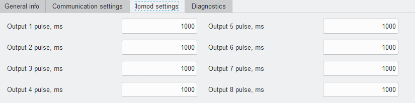
Fig. 5.4.3.1 output pulse settings
6. Communication protocols
The IOMod 8DI8DO supports three communication protocols: Modbus RTU, IEC 60870-5-101, and IEC 60870-5-103. These protocols allow a user, via a master device, to read data from the IOMod and send commands to activate digital outputs. The desired communication protocol can be selected using the IOMod Utility application (Fig. 6.1) The Utility's interface allows users to connect to IOMod via USB and RS485. More information about this tool and its installation can be found in the detailed IOMod Utility manual here.
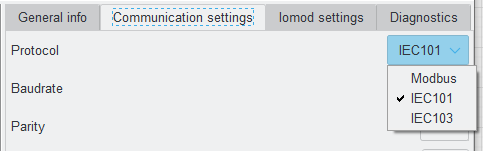 Fig. 6.1 IOMod utility app protocol selection window
Table 6.1 IOMod 8DI8DO default communication protocol settings
|
Protocol |
baudrate |
parity |
stop bits |
wait byte count |
slave address |
link address size |
ASDU size |
COT size |
IOA size |
Input function |
Output command function |
Output status function |
|---|---|---|---|---|---|---|---|---|---|---|---|---|
|
Modbus |
19200 | Even | 1 | 8 | 1 | |||||||
|
IEC 101 |
19200 | Even | 1 | 8 | 1 | 1 | 1 | 1 | 2 | |||
|
IEC 103 |
19200 | Even | 1 | 8 | 1 | 253 | 254 | 254 | ||||
*The default IOMod 8DI8DO communication protocol is Modbus
6.1 Modbus RTU protocol operational information
Modbus RTU protocol is a simple and widely used messaging structure for serial communication. In the case of the Modbus protocol IOMod 8DI8DO will send data only after receiving correct queries from a master device. Supported Modbus function codes: FC1, FC2, FC3, FC5, FC6 and FC16.
Communication settings
IOMod 8DI8DO configuration is performed via the IOMod Utility (the manual can be accessed here).
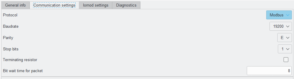 Fig. 6.1.1 Modbus protocol communication settings tab on the IOMod utility app
For Modbus protocol users can set: Link address, baudrate, parity, stop bits, terminating resistor, bit wait time (Fig. 6.1.1). See the table below for parameter range and default values (Table 6.1.1).
Table 6.1.1 Communication parameters range and default values
|
Parameter |
Range |
Default values |
|---|---|---|
| Link address | 1-256 | 1 |
| Baudrate | 600, 1200, 2400, 4800, 9600, 19200, 28800, 38400, 57600, 76800, 115200 | 19200 |
| Parity | None, Odd, Even, Mark, Space | Even |
| Stop bits | 1, 2 | 1 |
| Terminating resistor | Enable or disable | disabled |
| Bit wait time for packet | 8-256 | 8 |
01 (0x01) Read Coil status
As the name implies, it is designed to read digital data. In the context of IOMod 8DI8DO FC1, requests allow reading digital input and output statuses. Please note that the input statuses cannot be overwritten separately but can only be read (R access).
Table 6.1.2 8DI8DO inputs and outputs Modbus addresses to be read with FC1 requests
|
Coil Status FC01 |
|||
|---|---|---|---|
|
Address (Dec) |
Description |
Data type |
Access |
|
0 |
Read digital output DO1 |
BOOLEAN |
RW |
|
1 |
Read digital output DO2 |
BOOLEAN |
RW |
|
2 |
Read digital output DO3 |
BOOLEAN |
RW |
|
3 |
Read digital output DO4 |
BOOLEAN |
RW |
|
4 |
Read digital output DO5 |
BOOLEAN |
RW |
|
5 |
Read digital output DO6 |
BOOLEAN |
RW |
|
6 |
Read digital output DO7 |
BOOLEAN |
RW |
|
7 |
Read digital output DO8 |
BOOLEAN |
RW |
|
8 |
Read digital input DI1 |
BOOLEAN |
R |
|
9 |
Read digital input DI2 |
BOOLEAN |
R |
|
10 |
Read digital input DI3 |
BOOLEAN |
R |
|
11 |
Read digital input DI4 |
BOOLEAN |
R |
|
12 |
Read digital input DI5 |
BOOLEAN |
R |
|
13 |
Read digital input DI6 |
BOOLEAN |
R |
|
14 |
Read digital input DI7 |
BOOLEAN |
R |
|
15 |
Read digital input DI8 |
BOOLEAN |
R |
02 (0x02) Read Discrete Inputs
As the name implies, it is designed to read digital data. In the context of IOMod 8DI8DO FC2, requests allow reading digital input and output statuses. Please note that the input statuses cannot be overwritten separately but can only be read (R access).
Table 6.1.3 8DI8DO inputs Modbus addresses to be read with FC2 requests
|
Discrete Inputs FC02 |
|||
|---|---|---|---|
|
Address (Dec) |
Description |
Data type |
Access |
|
8 |
Read digital input DI1 |
BOOLEAN |
R |
|
9 |
Read digital input DI2 |
BOOLEAN |
R |
|
10 |
Read digital input DI3 |
BOOLEAN |
R |
|
11 |
Read digital input DI4 |
BOOLEAN |
R |
|
12 |
Read digital input DI5 |
BOOLEAN |
R |
|
13 |
Read digital input DI6 |
BOOLEAN |
R |
|
14 |
Read digital input DI7 |
BOOLEAN |
R |
|
15 |
Read digital input DI8 |
BOOLEAN |
R |
03 (0x03) Read Holding Registers
Allows the user to read counter/timer values dedicated to digital inputs. There are two types of values - Pulse Counter and On Timer. The pulse counter tracks the number of pulses for the respective input. While the On timer calculates the duration for which the respective input remained in its active state.
Table 6.1.4 8DI8DO input settings Modbus addresses to be read with FC3 requests
|
Holding Register FC03 |
|||
|---|---|---|---|
|
Address (Dec) |
Description |
Data type |
Access |
|
0 |
Input 1 pulse count |
UINT16 |
RW |
|
1-2 |
Input 1 on time |
UINT32 |
RW |
|
3 |
Input 2 pulse count |
UINT16 |
RW |
|
4-5 |
Input 2 on time |
UINT32 |
RW |
|
6 |
Input 3 pulse count |
UINT16 |
RW |
|
7-8 |
Input 3 on time |
UINT32 |
RW |
|
9 |
Input 4 pulse count |
UINT16 |
RW |
|
10-11 |
Input 4 on time |
UINT32 |
RW |
|
12 |
Input 5 pulse count |
UINT16 |
RW |
|
13-14 |
Input 5 on time |
UINT32 |
RW |
|
15 |
Input 6 pulse count |
UINT16 |
RW |
|
16-17 |
Input 6 on time |
UINT32 |
RW |
|
18 |
Input 7 pulse count |
UINT16 |
RW |
|
19-20 |
Input 7 on time |
UINT32 |
RW |
|
21 |
Input 8 pulse count |
UINT16 |
RW |
|
22-23 |
Input 8 on time |
UINT32 |
RW |
05 (0x05) Write single coil
This command is used to set the state of a single output (On or Off). The output addresses range from 0 to 7 (the first output is address 0, the last output is address 7).
15 (0x0F) Write Multiple Coils
This function code requests are used to control multiple digital outputs at once. Since there are only 8 outputs the control data are always packed into one byte, so it is very important to specify the number of outputs to be effected.
Table 6.1.5 8DI8DO output Modbus addresses to be written with FC5 or FC15 requests
|
Address (Dec) |
Description |
Data type |
Access |
|---|---|---|---|
|
0 |
Write digital output DO1 |
BOOLEAN |
W |
|
1 |
Write digital output DO2 |
BOOLEAN |
W |
|
2 |
Write digital output DO3 |
BOOLEAN |
W |
|
3 |
Write digital output DO4 |
BOOLEAN |
W |
|
4 |
Write digital output DO5 |
BOOLEAN |
W |
|
5 |
Write digital output DO6 |
BOOLEAN |
W |
|
6 |
Write digital output DO7 |
BOOLEAN |
W |
|
7 |
Write digital output DO8 |
BOOLEAN |
W |
06 (0x06) Preset Single Register
Sets a single register. This command is used to change the values of "Pulse counter" and "ON timer".
16 (0x10) Preset Multiple Registers
Sets multiple registers. This command is used to change the values of "Pulse counter" and "ON timer".
6.2 IEC 60870-5-101 protocol operational information
IEC 60870-5-101 (IEC101) is a communication protocol designed for telecontrol applications in power systems, facilitating communication between a master station and slave devices (RTUs). Unlike the Modbus protocol, IEC101 allows to transfer of additional information like timestamp and quality attributes.
Communication settings
IOMod 8DI8DO configuration is performed via the IOMod Utility application (the manual can be accessed here).
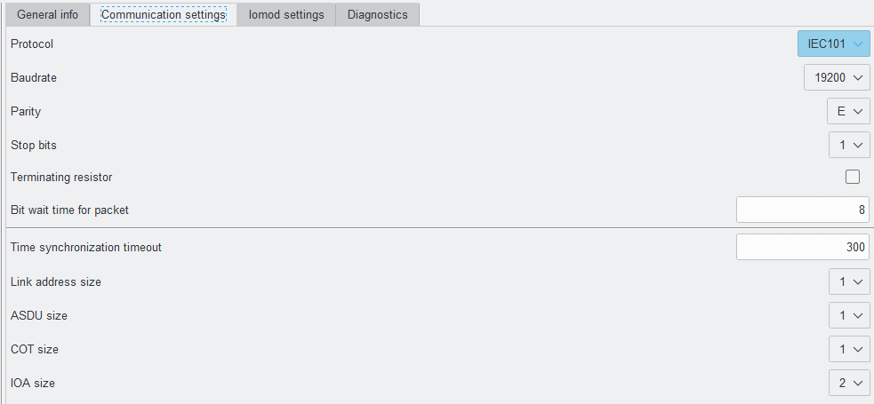
Fig. 6.2.1 Communication settings on the IOMod utility application
For IEC 60870-5-101 protocol users can set: Link address, baudrate, parity, stop bits, terminating resistor and bit wait time, time synchronization timeout, link address size, ASDU size, COT size, and IOA size using the IOMod utility application (Fig 6.2.1) See the table below for parameter ranges and default values for IEC 60870-5-101 protocol (Fig 6.2.1).
Table 6.2.1 Parameter ranges and default values of IOMod
|
Parameter |
Range |
Default values |
|---|---|---|
| Link address | 1-254* | 1 |
| Baudrate | 600, 1200, 2400, 4800, 9600, 19200, 28800, 38400, 57600, 76800, 115200 | 19200 |
| Parity | None, Odd, Even, Mark, Space | Even |
| Stop bits | 1, 2 | 1 |
| Terminating resistor | Enable or disable | disabled |
| Bit wait time for packet | 8-256 | 8 |
| Time synchronization timeout (s) | 1-65535 | 300 |
| Link address size | 1, 2 | 1 |
| ASDU size | 1, 2 | 1 |
| COT size | 1, 2 | 1 |
| IOA size | 1, 2, 3 | 2 |
* Although 2 bytes can be set for the size of the link address, the maximum address allowed is 254.
The IOMod 8DI8DO uses the IEC101 protocol to transmit signals in a standardized format. Each signal is mapped to an Information Object Address (IOA) and assigned a Type Identifier (TI). This format conveys binary status changes (e.g., whether a circuit breaker is open or closed) with associated timestamps.
Time synchronization is critical for logging events. To synchronize time, the master sends a Time Sync command C_CS_NA_1 (103) with Cause of Transmission (COT) 6. According to the IEC 60870-5-101 protocol specification, time synchronization can be performed for multiple devices using broadcast messages. A master device sends a broadcast timesync command with a broadcast link address. This ensures consistent time-stamping for event recording and fault detection across the network.
Table 6.2.2 IEC 60870-5-101 protocol register table
|
IOA |
Description |
Type |
|
1 |
output 1 SPI event |
30 (M_SP_TB_1) |
|
2 |
output 2 SPI event |
30 (M_SP_TB_1) |
|
3 |
output 3 SPI event |
30 (M_SP_TB_1) |
|
4 |
output 4 SPI event |
30 (M_SP_TB_1) |
|
5 |
output 5 SPI event |
30 (M_SP_TB_1) |
|
6 |
output 6 SPI event |
30 (M_SP_TB_1) |
|
7 |
output 7 SPI event |
30 (M_SP_TB_1) |
|
8 |
output 8 SPI event |
30 (M_SP_TB_1) |
|
9 |
Input 1 SPI event |
30 (M_SP_TB_1) |
|
10 |
Input 2 SPI event |
30 (M_SP_TB_1) |
|
11 |
Input 3 SPI event |
30 (M_SP_TB_1) |
|
12 |
Input 4 SPI event |
30 (M_SP_TB_1) |
|
13 |
Input 5 SPI event |
30 (M_SP_TB_1) |
|
14 |
Input 6 SPI event |
30 (M_SP_TB_1) |
|
15 |
Input 7 SPI event |
30 (M_SP_TB_1) |
|
16 |
Input 8 SPI event |
30 (M_SP_TB_1) |
|
101 |
output 1 SPI command |
45 (C_SC_NA_1) |
|
102 |
output 2 SPI command |
45 (C_SC_NA_1) |
|
103 |
output 3 SPI command |
45 (C_SC_NA_1) |
|
104 |
output 4 SPI command |
45 (C_SC_NA_1) |
|
105 |
output 5 SPI command |
45 (C_SC_NA_1) |
|
106 |
output 6 SPI command |
45 (C_SC_NA_1) |
|
107 |
output 7 SPI command |
45 (C_SC_NA_1) |
|
108 |
output 8 SPI command |
45 (C_SC_NA_1) |
Table 6.2.3 IEC 60870-5-103 protocol register table for grouped inputs/outputs
|
IOA |
Description |
Type |
|
1 |
output 1-2 DPI event |
31 (M_DP_TB_1) |
|
3 |
output 3-4 DPI event |
31 (M_DP_TB_1) |
|
5 |
output 5-6 DPI event |
31 (M_DP_TB_1) |
|
7 |
output 7-8 DPI event |
31 (M_DP_TB_1) |
|
9 |
Input 1-2 DPI event |
31 (M_DP_TB_1) |
|
11 |
Input 3-4 DPI event |
31 (M_DP_TB_1) |
|
13 |
Input 5-6 DPI event |
31 (M_DP_TB_1) |
|
15 |
Input 7-8 DPI event |
31 (M_DP_TB_1) |
|
101 |
output 1-2 DPI command |
46 (C_DC_NA_1) |
|
103 |
output 3-4 DPI command |
46 (C_DC_NA_1) |
|
105 |
output 5-6 DPI command |
46 (C_DC_NA_1) |
|
107 |
output 7-8 DPI command |
46 (C_DC_NA_1) |
* SPI - single-point information, DPI - double-point information
To read single-point inputs/outputs, the TI 30 is used, which provides single-point information with a time tag. If double-point inputs/outputs need to be read, TI 31 is used, which provides information with a time tag.
TI 45 is used to send a command to a single-point output, whereas TI 46 is used to send a command to a double-point output. The outputs are controlled by the master (controlling station).
Table 6.2.4 Double-point states
| Value | State |
| 00 | intermediate |
| 01 | off |
| 10 | on |
| 11 | error |
6.3 IEC 60870-5-103 protocol operational information
Communication settings
IOMod 8DI8DO configuration is performed via the IOMod Utility application (the manual can be accessed here).
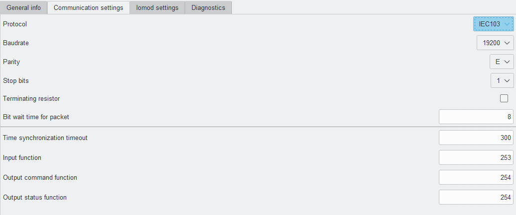
Fig. 6.3.1 Communication settings on the IOMod utility application
For IEC 60870-5-103 protocol users can set: Link address, baudrate, parity, stop bits, terminating resistor, and bit wait time, time synchronization timeout, and input function using the IOMod utility application (Fig. 6.3.1). See the table below for parameter ranges and default values for IEC 60870-5-103 protocol (Table 6.3.1).
Table 6.3.1 Parameter ranges and default values of IOMod
|
Parameter |
Range |
Default values |
|---|---|---|
|
Link address |
1-256 |
1 |
| Baudrate | 600, 1200, 2400, 4800, 9600, 19200, 28800, 38400, 57600, 76800, 115200 | 19200 |
| Parity | None, Odd, Even, Mark, Space | Even |
| Stop bits | 1, 2 | 1 |
| Terminating resistor | Enable or disable | disabled |
| Bit wait time for packet | 8-256 | 8 |
| Time synchronization timeout (s) | 1-65535 | 300 |
| Input function | 253 | |
| Output command function | 254 | |
| Output status function | 254 |
When the IEC-60870-5-103 protocol is selected, IOMod 8DI8DO uses a standard communication scheme. Initiation, control messages, and queries are initiated by a master (controlling station), while the IOMod device (controlled station) only answers requests and sends values. The first message sent by the master should be RESET CU to restart communication. When an acknowledge (ACK) packet is sent from a slave device, a master may proceed with acquiring General Interrogation and sending Time synchronization packets.
When this initialization is complete, the master should poll the IOMod device with Class 1 and Class 2 requests. Class 2 is used when the master polls for cyclic data. The controlled device responds when spontaneous data exists and the master then sends a request for Class 1. The controlled station responds with a time-tagged message.
|
Type |
INF |
FUN |
Description |
|
1 (M_TTM_TA_3) |
1 |
253 |
Input 1 event |
|
1 (M_TTM_TA_3) |
2 |
253 |
Input 2 event |
|
1 (M_TTM_TA_3) |
3 |
253 |
Input 3 events |
|
1 (M_TTM_TA_3) |
4 |
253 |
Input 4 event |
|
1 (M_TTM_TA_3) |
5 |
253 |
Input 5 event |
|
1 (M_TTM_TA_3) |
6 |
253 |
Input 6 event |
|
1 (M_TTM_TA_3) |
7 |
253 |
Input 7 event |
|
1 (M_TTM_TA_3) |
8 |
253 |
Input 8 event |
|
1 (M_TTM_TA_3) |
1 |
254 |
output 1 event |
|
1 (M_TTM_TA_3) |
2 |
254 |
output 2 event |
|
1 (M_TTM_TA_3) |
3 |
254 |
output 3 event |
|
1 (M_TTM_TA_3) |
4 |
254 |
output 4 event |
|
1 (M_TTM_TA_3) |
5 |
254 |
output 5 event |
|
1 (M_TTM_TA_3) |
6 |
254 |
output 6 event |
|
1 (M_TTM_TA_3) |
7 |
254 |
output 7 event |
|
1 (M_TTM_TA_3) |
8 |
254 |
output 8 event |
|
1 (M_TTM_TA_3) |
1 |
254 |
output 1 command |
|
1 (M_TTM_TA_3) |
2 |
254 |
output 2 command |
|
1 (M_TTM_TA_3) |
3 |
254 |
output 3 command |
|
1 (M_TTM_TA_3) |
4 |
254 |
output 4 command |
|
1 (M_TTM_TA_3) |
5 |
254 |
output 5 command |
|
1 (M_TTM_TA_3) |
6 |
254 |
output 6 command |
|
1 (M_TTM_TA_3) |
7 |
254 |
output 7 command |
|
1 (M_TTM_TA_3) |
8 |
254 |
output 8 command |
Table 6.3.3 IEC 60870-5-103 protocol register table for grouped inputs/outputs
|
Type |
INF |
FUN |
Description |
|
1 (M_TTM_TA_3) |
1 |
253 |
Input 1-2 event |
|
1 (M_TTM_TA_3) |
3 |
253 |
Input 3-4 event |
|
1 (M_TTM_TA_3) |
5 |
253 |
Input 5-6 event |
|
1 (M_TTM_TA_3) |
7 |
253 |
Input 7-8 event |
|
1 (M_TTM_TA_3) |
1 |
254 |
output 1-2 event |
|
1 (M_TTM_TA_3) |
3 |
254 |
output 3-4 event |
|
1 (M_TTM_TA_3) |
5 |
254 |
output 5-6 event |
|
1 (M_TTM_TA_3) |
7 |
254 |
output 7-8 event |
|
1 (M_TTM_TA_3) |
1 |
254 |
output 1-2 command |
|
1 (M_TTM_TA_3) |
3 |
254 |
output 3-4 command |
|
1 (M_TTM_TA_3) |
5 |
254 |
output 5-6 command |
|
1 (M_TTM_TA_3) |
7 |
254 |
output 7-8 command |
Table 6.3.4 Double-point states
| Value | State |
| 00 | intermediate |
| 01 | off |
| 10 | on |
| 11 | error |