IOMOD 8DI8DO User Manual Modbus
Introduction
IOMOD 8DI8DO is a compact size stand-alone Modbus (RTU) or IEC 60870-5-103 digital input and digital output controller. IOMOD is used for industrial applications, where digital signaling is used and robust communication is needed. IOMOD is ideal solution for applications such as data acquisition, observation, control, process monitoring, testing and measurement at remote places. It is controlled over Modbus or IEC 60870-5-103 protocol, and can be used with any SCADA system.
Features
- 8 digital inputs with configurable active signal polarity, or input inversion; Pulse count and ON time count
- 8 digital open collector outputs for relays
- Galvanically isolated inputs and outputs
- Configurable over USB
- Drag And Drop firmware upgrade over USB
- RS485 communication
- LED input / output indications, + Data transmission (Rx and Tx) indication.
- Spring contact connectors
- Small sized case with removable front panel
- DIN rail mount
- Operating temperature
- Power Requirements: 12-24 VDC
Device operational information
IOMOD 8DI8DO uses Modbus (RTU) or IEC 60870-5-103 protocol over the RS485 interface. The protocol used by the device can be changed by uploading the corresponding firmware. Default communication settings are: 9600 baudrate, 8N1, Slave address - 1.
Status LED
Status LED can be in 3 colors :
Red - Missing power souce to the outputs.
Blue - Device connected to USB.
Green - Normal operation.
Rx/Tx LED
The RX/TX LED on the IOMod flashes when data is either being transmitted or received via the RS485 port.
MODBUS operational information
To read output status, send 01 Modbus command (Read Coils) with resolution of the first register (0), and size of 8. Returned value will show all 8 output states (1 - turned On, 0 - turned Off).
To read input status, send 02 Modbus command (Read Discrete Inputs) with resolution of first register (0) and size of 8. Returned value will show 8 input states.
To read input counter values, send 04 Modbus command (Read Input Registers) or 03 Modbus command (Read Holding Registers) with resolution of first register (0) and size of 24. Returned data will show pulse count (first register) and ON time (2nd and 3rd registers) for each input – pulse count of input #2 will be at register 4th, and so on. ON time will be shown as seconds. ON time and pulse count will increase when input pulse is longer than Filter time, which is configured by user in USB terminal menu. Shorter pulses will be ignored in both pulse and ON time registers. From software version 1.10, as capacity of input counter expanded to 32-bits, additional 16 registers depict such wider values in registers 00023-00039.
These input counter values can be changed by using 06 Modbus command.
To turn single output on or off, send command 05 (Write Single Coil), with output address (0 to 7). To turn output on – send hex value FF00; to turn off – hex value 0000.
To turn multiple outputs on or off, use command 15 (Write Multiple Coils), and send binary coded value for 8 coils at address (0) and length 8.
To invert input states by software, or to use pull-up resistors on inputs, configure device over USB terminal. Useable Modbus commands shown in table below.
Supported MODBUS functions
01 (0x01) Read Coil Status
Reads status of relays (Off or On). IOMOD 8DI8DO has 8 digital outputs from address 0 to address 7.
02 (0x02) Read Discrete Inputs
Reads status of digital inputs (Off or On). IOMOD 8DI8DO has 8 digital inputs from address 0 to address 7; These inputs are active-high by default; user can turn on pull-up resistors (through USB) to these inputs to make them active-low.
03 (0x03) Read Holding Registers
Lets user read counter/timer values dedicated to digital inputs. There are 40 MODBUS registers. Values held in these registers are explained in a table below. There are two types of values - Pulse Counter and On Timer, the latter calculating the time that respective input was held in its active state.
04 (0x04) Read Input Registers
Lets user read counter/timer values dedicated to digital inputs. There are 80 MODBUS registers. Values held in these registers are explained in a table below. There are two types of values - Pulse Counter and On Timer, the latter calculating the time in seconds that respective input was held in its active state. This function is deprecated and mirrors function 0x03 to conform to past versions of IOMOD 16DI.
05 (0x05) Write Single Coil
Sets single digital output On or Off. Output addresses from 0 to 7 (first output – address 0, last output – address 7).
06 (0x06) Preset Single Register
Sets single register. Register addresses is identical to “Read Input Registers” addresses.
15 (0x0F) Write Multiple Coils
Sets multiple digital output On or Off. Output addresses from 0 to 7 (first output – address 0, last output – address 7).
Modbus register mapping table
| Register | Description | Value range |
| Read coil status (01) | ||
| 00000-00007 | Reading digital outputs DO1-DO8 |
0 - 255 |
| Read discrete inputs (02) | ||
| 00000-00007 | Reading digital inputs DI1-DI8 |
0 - 255 |
| Read holding register (03), Read input register (04), Preset Single Register (06) | ||
| 00000 | Pulse count for DI1, Least Significant Word |
0 - 65 535 |
| 00001-00002 | On time, in seconds, for DI1, Least Significant Word first* |
0 - 4 294 967 295 |
| ... | ... | ... |
| 00021 | Pulse count for DI8, Least Significant Word | 0 - 65 535 |
| 00022-00023 | On time, in seconds, for DI8, Least Significant Word first* |
0 - 4 294 967 295 |
| 00024-00039 | Pulse count for DI1-DI8, Least Significant Word first* |
0 - 4 294 967 295 |
| Write single coil (05) | ||
| 00000-00007 | Writing digital outputs DO1-DO8 | 0x0000 / 0xFF00 |
| Write multiple coils (15) | ||
| 00000-00007 | Writing multiple digital outputs DO1-DO8 | 0 - 255 |
*It is advised to set most significant word of counter/timer first
Testing With “THE VINCI” software
To test IOMOD with default settings for Modbus, user connects device through RS485 to Modbus master. Example using “The Vinci Expert” device as serial interface converter and adapter to PC with “The Vinci” software. Default settings for Modbus – 9600 baudrate; 8 data, no parity, 1 stop bit. When opening “The Vinci” software, choose Modbus serial – Master mode. In settings tab, choose station number (default – 1); configure tags (as described in section 3.A. Modbus working information); Press start and go to “Statistic” tab:

Fig. 3.1. Statistic Tab in “The Vinci” software
To test IOMOD with default settings, user connects device through RS485 to IEC 60870-5-103 master. Example using “The Vinci Expert” as serial interface converter and adapter to PC with “The Vinci” software. When opening “The Vinci” software, choose IEC 60870-5-103 – Master mode. Initial settings – 9600 baudrate; 8 data, no parity, 1 stop bit. Press start, send time synchronization, General interrogation and go to “Statistic” tab:
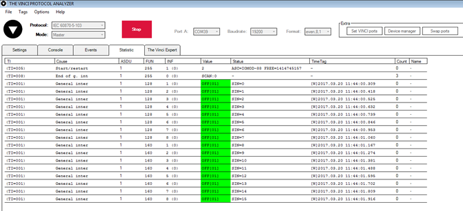 Fig. 3.5
As seen in Fig. 3.5, Outputs and inputs are shown with info numbers 1-8, and function type is 128 and 160 respectively.
GI, time synchronization and general command options can be found at right side of the program, in “System” tab.
Output commands are controlled by “General command” window at right side of the program, in “System” tab, with Output address (Function type) 128, and output number (Info number). Fig. 3.6 shows 1st and 6th output command sent and “CMD ACK” response received.
Fig. 3.7 shows first 4 Outputs and last 4 Inputs grouped (notice order of info numbers).
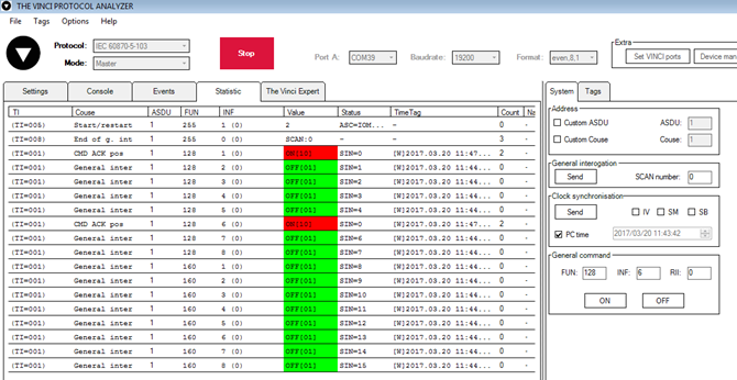
Fig. 3.6
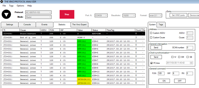 Fig. 3.7
Technical information
| System | ||
| 1. | Dimensions | 101 x 119 x 17.5, mm |
| 2. | Case | ABS, black |
| 3. | Working environment | Indoors |
| 4. | Working temperature |
-30 ⎟ +70°C |
| 5. | Recommended operating conditions | 5 – 60°C and 20 – 80%RH; |
| 6. | Configuration | USB |
| 7. | Firmware upgrade | USB – mass storage device |
| Electrical specifications | ||
| 8. | Inputs | 8 X 2kV isolated 12-24VDC; Selectable inversion. |
| 9. | Outputs | 8 X 2kV isolated open collector outputs (300mA each, Max 50V); |
| Power | ||
| 10. | Power Supply | 9V to 33V |
| 11. | Current consumption |
38mA @ 12VDC, 20mA @ 24VDC |
Mounting and installation guide
IOMOD 8DI8DO RS485 interface
IOMOD 8DI8DO has integrated 120Ω termination resistor which can be enabled or disabled over USB configuration. It is recommended to use termination at each end of the RS485 cable. See typical connection diagram on Fig. 5.1.
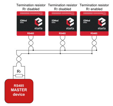 Fig. 5.1. Connection example of RS485 interface
IOMOD 8DI8DO has 1/8 Unit load receiver which allows to have up to 256 units on line (compared to standard 32 units). To reduce reflections, keep the stubs (cable distance from main RS485 bus line) as short as possible when connecting device.
IOMOD 8DI8DO inputs
Typical application of IOMOD 8DI8DO inputs is shown on Fig. 5.2. When default configuration for inputs is applied, user will see inputs connected to +12/24V as “high” or state “1” and input status LED will glow.
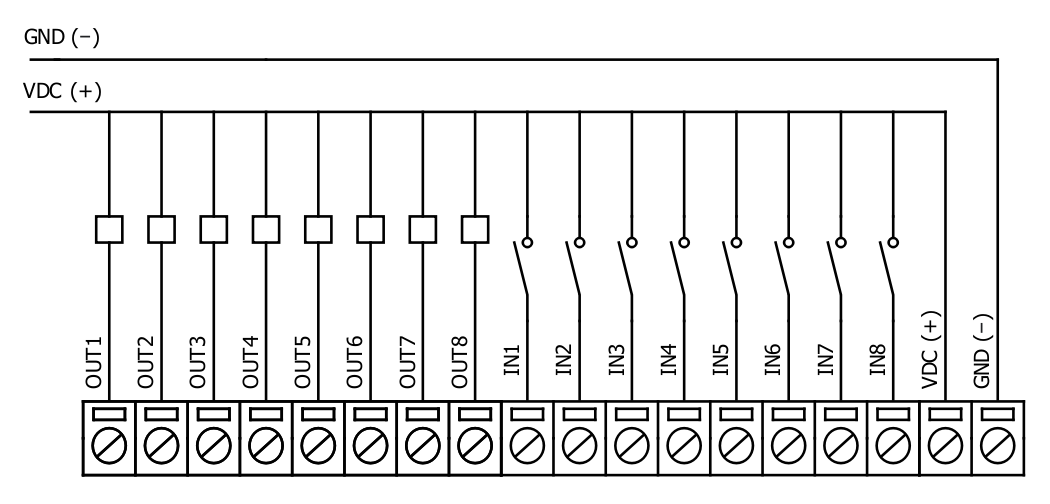
Fig. 5.2. Typical application
User also can configure to enable internal input pull-up resistors (function is applied for all inputs) and software input inversion. With this configuration, user will see inputs connected to 0V (see Fig. 5.3) as “high” or state “1”, input status LED will NOT glow.
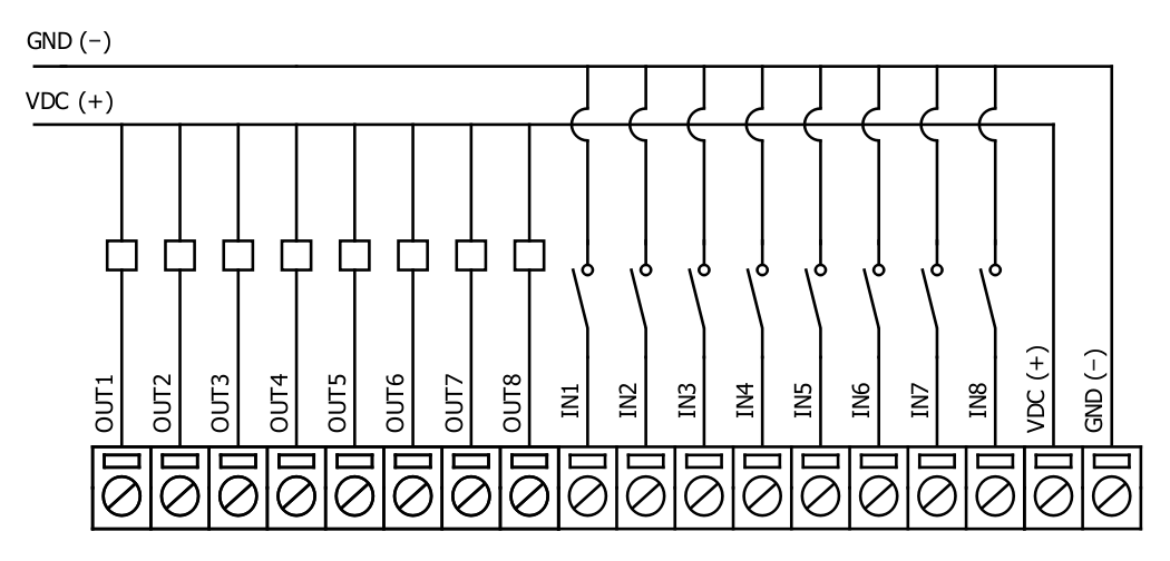
Fig. 5.3. Input configuration
IOMOD 8DI8DO outputs
IOMOD 8DI8DO has 8 open collector digital outputs. Internal clamp diodes are connected to each output which makes IOMOD 8DI8DO ideal for driving inductive loads like relays. Maximum 300mA per output is allowed. For higher loads outputs can be connected in parallel. Make sure your power supply can provide enough power. Typical application of outputs is shown on Fig. 5.4
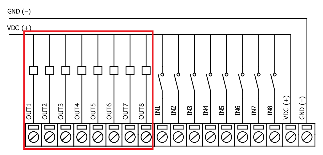
Fig. 5.4. Output configuration
Configuration over USB
Driver installation
Device requires USB drivers to work as virtual com port. First-time connection between device and computer could result in “Device driver software was not successfully installed” error.
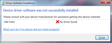 Fig. 6.1. Device driver error
User then manually installs drivers by selecting downloaded driver folder:
Go to Control Panel -> Device Manager;
Select failed device;
Press “Update driver software”; following screen should appear:
 Fig. 6.2. Driver update screen
Select “x86” driver for 32bit machine, or x64 for 64bit machine. If not sure, select root folder (folder in which x64 and x86 lays inside).
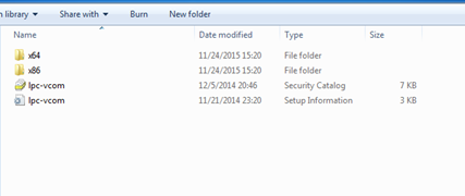
Fig. 6.3. Driver folder for IOMOD device
IOMOD configuration with PuTTY terminal
Configuration of IOMOD device is done through CLI (Command Line Interface) on virtual COM port. Drivers needed for MS Windows to install VCOM will be provided. To open up CLI simply connect to specific V-COM port with terminal software (advised to use PuTTY terminal software. If other software is being used, user might need to send <return> symbol after each command). When connected user should immediately see main screen (Fig. 6.4.)
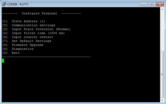 Fig. 6.4. Main configuration menu
If accidentally closed the terminal window, user can connect terminal program again, and press any key on keyboard to show up main menu.
Main Menu
|
Menu Name |
Function |
Values |
Default Values |
|
| 1. |
Slave Address |
Modbus Slave address / ID |
1-247 |
(default: 1) |
| 2. |
Communication settings |
Enters baudrate, data and parity bit screen |
- |
(default: 9600; 8+1+N) |
| 3. |
Input pull-up enable |
Enables input pull-up resistor. Inputs then activated by low signal |
0 - 1 (off/on) |
(default: 1) |
| 4. |
Input State Inversion |
Input inversion (Inverts input states in modbus) |
0 - 1 (off/on) |
(default: 0) |
| 5. |
Input filter time |
Filter for short input pulses |
0 - 256000 (ms) |
(default: 100) |
| 6. |
Input counter restart |
Restarts all input counter registers to 0 |
(1 to confirm, 0 to cancel) |
- |
| 7. |
Set Default Settings |
Sets Default Settings |
(1 to confirm, 0 to cancel) |
- |
| 8. |
Firmware Upgrade |
Mass Storage Device Firmware Upgrade |
(1 to confirm, 0 to cancel) |
- |
| 9. |
Diagnostics |
Input / Output states |
- |
- |
| 0. |
Exit |
Exit and disconnect |
- |
- |
Protocol simulator
After entering diagnostics screen user can turn on protocol simulator by pressing [9]. When protocol simulator is turned on, device will communicate through USB port rather than RS-485 line. Communication on RS-485 line is closed and all Modbus commands will be accepted only from USB. To exit this mode user must restart device.
Firmware upgrade over USB
To update device firmware user must enter main configuration menu.
Enter Firmware update screen by pressing [4];
Confirm update by pressing [1];
Device now enters Firmware Upgrade mode. Device reconnects as mass storage device (Fig 6.5.).
It is recommended to close terminal window after entering firmware upgrade mode.
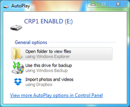 Fig. 6.5. Mass storage device warning
User then must delete existing file “firmware.bin”, and simply upload new firmware file by drag and drop.
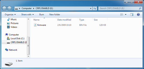 Fig. 6.5. Dragging and dropping new firmware file
Reconnect device and check firmware version. It should now represent the one it was updated to.