Connecting two IOMod 16DI
Description
This article describes how to connect and configure two IOMods 16DI to the WCC Lite using IEC103, and Modbus RTU.
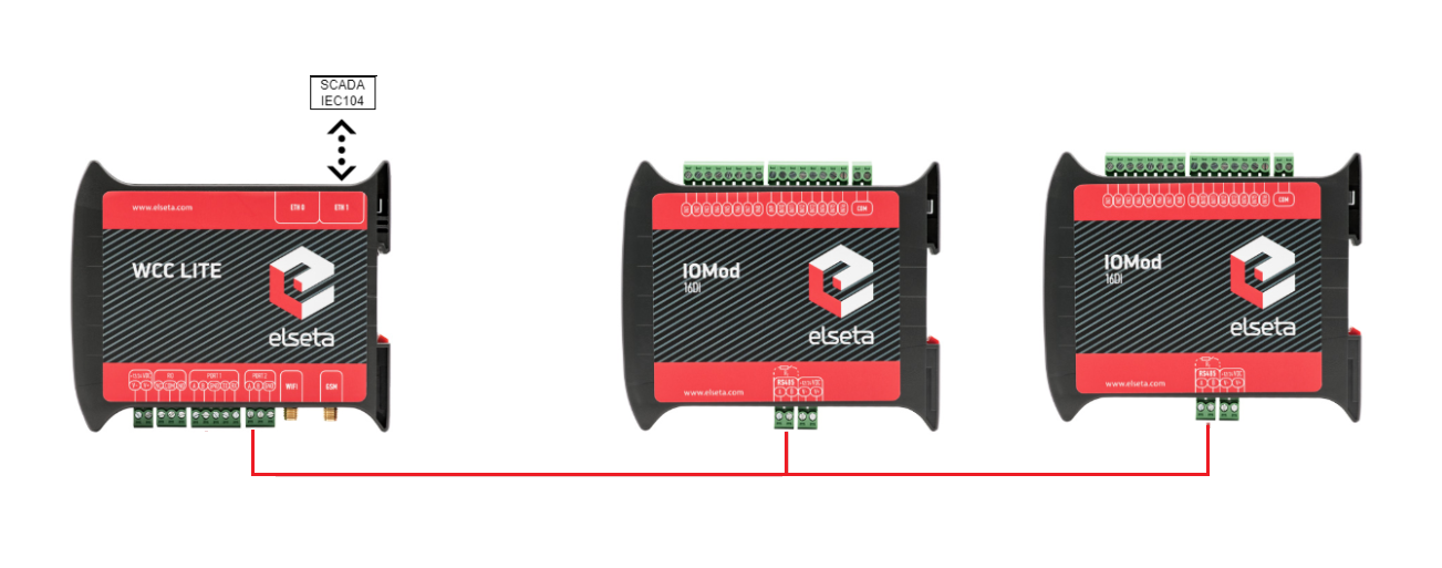
Typical connection schematic for two IOMod 16DI
WCC Lite can be connected to two IOMod 16DI via PORT1 or PORT2.
Preparing the configuration
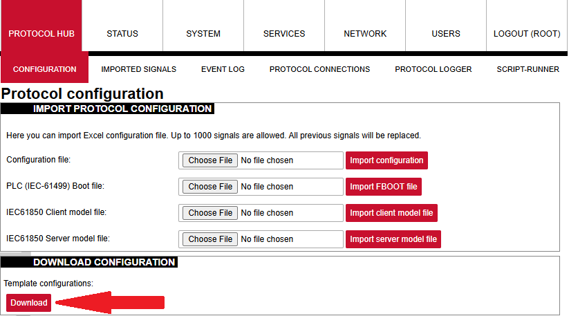
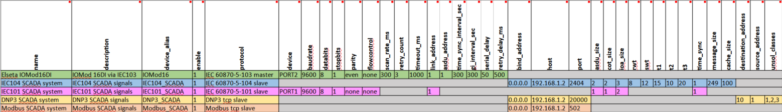
At first, you need to make a configuration for the WCC Lite. This can be done using any spreadsheet editing program. Templates for configuration can be found on the WCC Lite web. Protocol Hub --> Configuration. At the bottom of the page, there will be a Download button for template configurations.
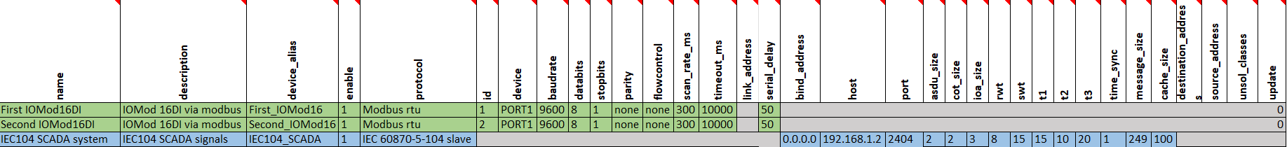
You need to configure the Devices and Signals sheets before continuing. These template configurations can also be used to configure protocols like Modbus-master and DNP3. Configuration can be modified according to the functionality needed. In this case, the Device sheet will only have three devices: WCC Lite and two IOMod 16DI. It is important to use only one protocol for each port, otherwise configuration will not work.
You can download the example configuration for each firmware version at the bottom of the article, or create your own using these links:
You need to configure the devices and signal sheets before continuing. After downloading template configurations, open the phub templates folder. You will see that there are different template folders for each IOMod:
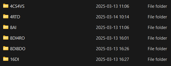
To select a correct configuration, check the sticker on the back of the IOMod. There, you will find which protocol to use according to Factory FW type. For example, if you have IOMod 16DI with IEC103 FW, select configuration iomod_16DI_IEC103_to_IEC104_DNP3_Modbus_SCADA.
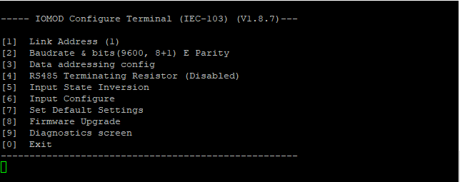
IOMOD needs to be configured, as in the Excel configuration. If templates are being used, default parameters should be set for the IOMOD. IOMODs with firmware version 1 are configured via PuTTY or other SSH programs using the USB port on the device's front panel. This can be done following the IOMod 16DI user manual.
IOMOD also has a series of parameters that can be configured directly for the IOMOD without changing the WCC Lite configuration. Each IOMOD has its unique parameters, which can be seen on the configuration menu.
The user can also change the input filter time. This parameter is set in milliseconds and determines the time after which the input is represented with the changed state. For example, if the filter time is 1000ms, and the input has been on for 500ms, the state won't change from OFF to ON. This is relevant when seeking to avoid unnecessary data.
Uploading configuration
Template configurations can work with default settings without any further changes. These template configurations can also be used to configure protocols like Modbus-master and DNP3. Configuration can be modified according to the functionality needed. For that, you can rely on the examples given in the links above (Preparing the configuration). If you need to specify different IEC104 slave settings, you can do that by changing the Excel configuration. By changing settings such as info_address or data_type, you can adapt the IEC104 slave to work as needed. To test this example, specify your computer's IP address in the Excel configuration for the IEC104 slave.
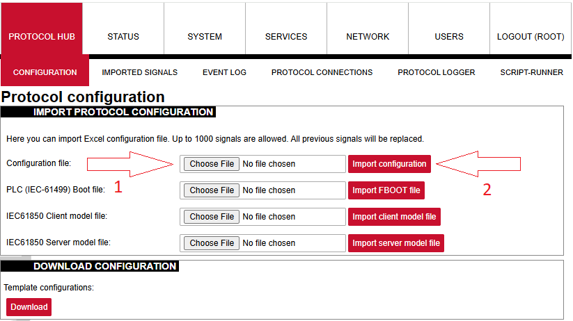
After the configuration is ready, upload it to WCC Lite (Configuration --> Choose file --> Import configuration):
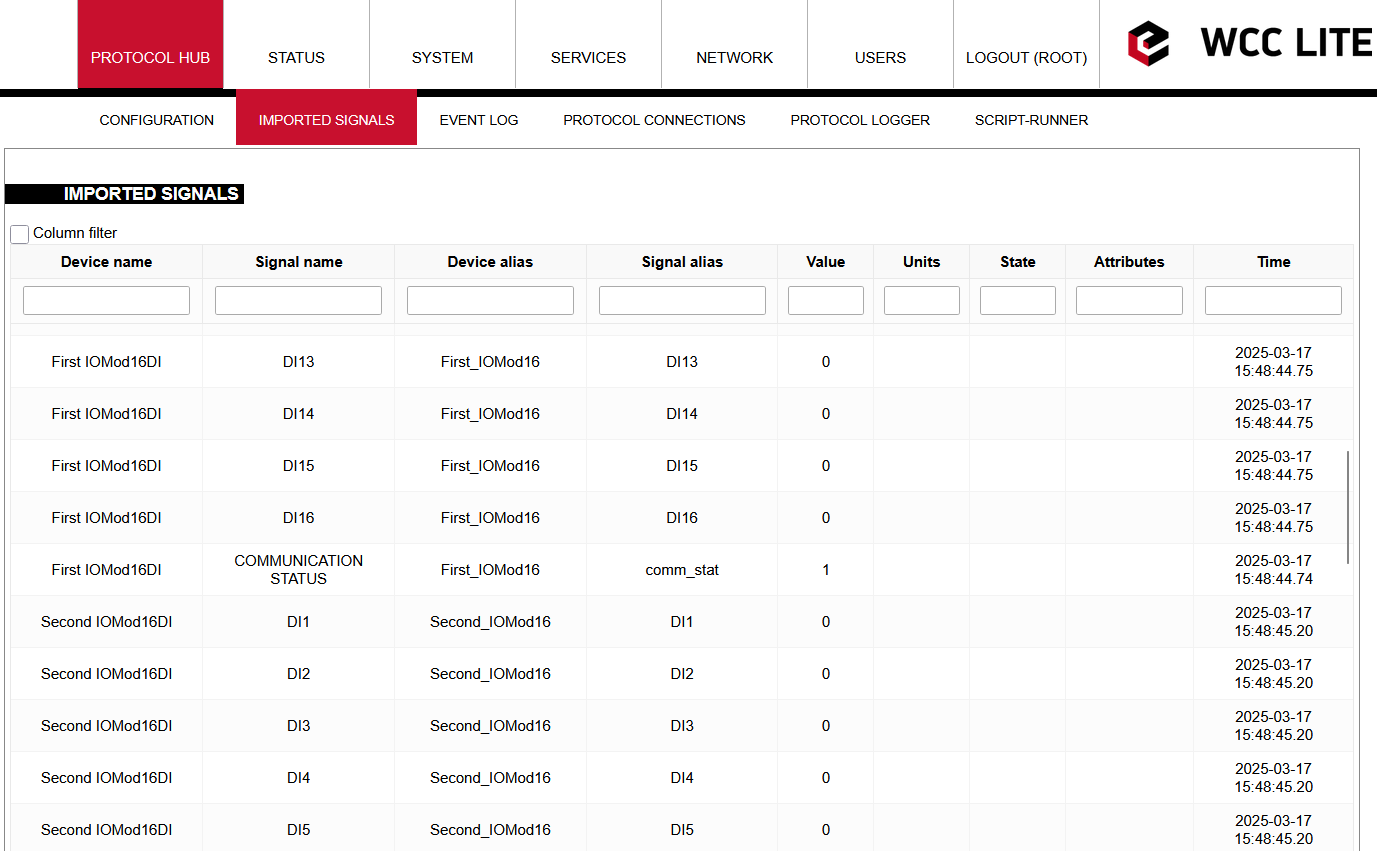
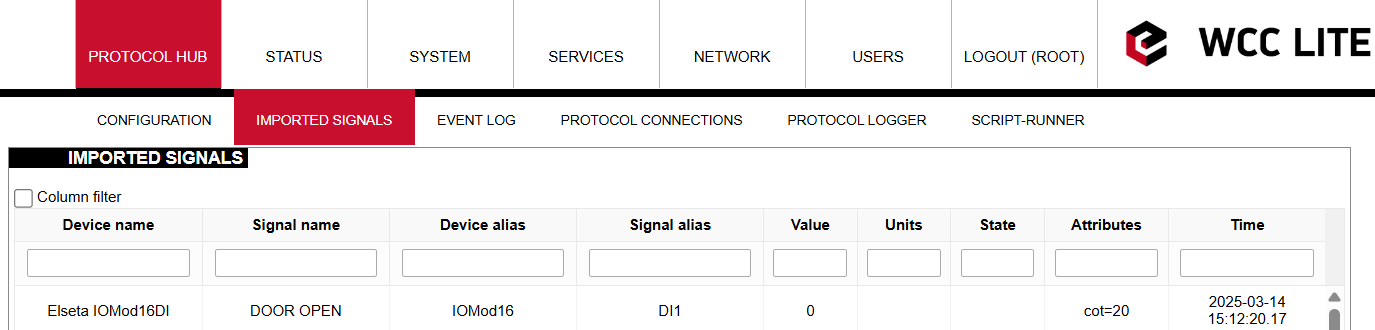
After the upload is done and no errors were detected, you should see all imported signals (Protocol Hub --> Imported signals):
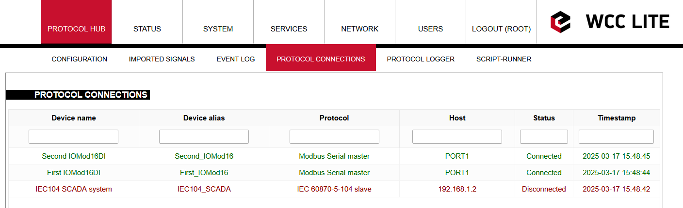
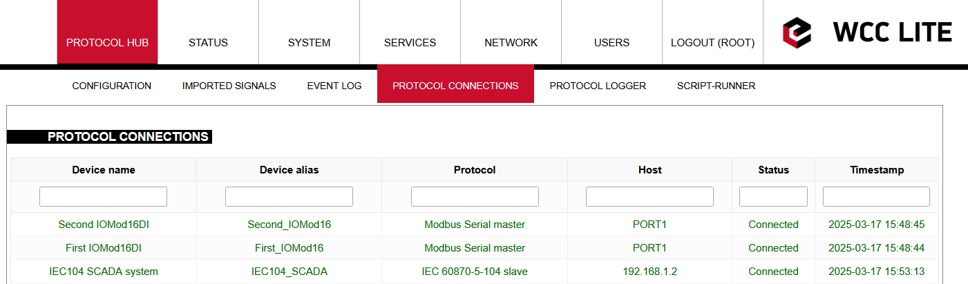
Before doing anything further, you should also check for protocol connections if both IOMod 16DI are connected to WCC Lite via PORT1. Go to Protocol connections, where you can see all the connected slave and master protocol devices:
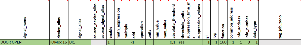
You can also change signal names according to your needs:
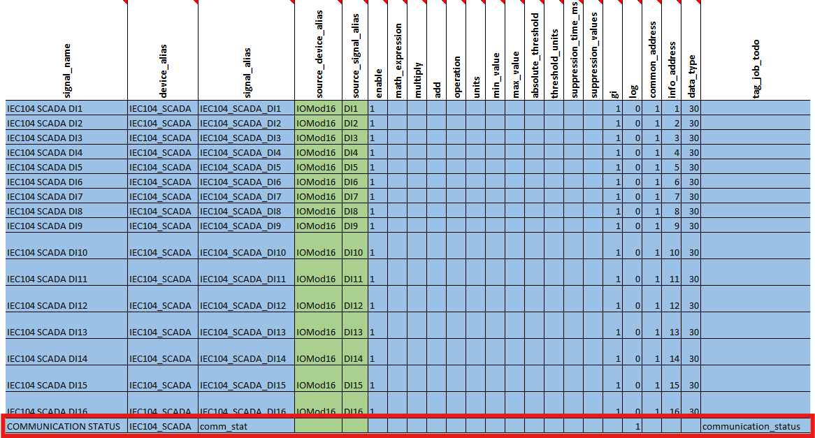
In every signals sheet, you can see a signal named COMMUNICATION STATUS. It is an indicator that shows whether the service is running and whether there is a connection with the device.
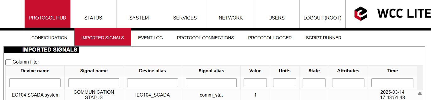
If everything is connected and service is running, COMMUNICATION STATUS should display 1. Otherwise, if not, it should display 2.
If IOMOD needs to be connected to another port, this could also be changed in the configuration. On the Device sheet, change the Device value from PORT1 to PORT2:
When configuring ports, please note that there can be 2 of the same protocol on the same port (with different IDs, link addresses, etc.), but there cannot be 2 different protocols on the same port.
Connecting IEC104-slave via Vinci
After Excel and USB configurations, you can connect to the device using the Vinci software. To simulate an IEC 104 slave, you need to choose the IEC 60870-5-104 protocol and Master(Client) mode and press start. In the Settings tab, check Structure, Timeouts and Windows values to match Excel configuration.

Then set the correct IP address and Port at the top of the program page. Port for IEC104 should be 2404, and IP address should match your WCC Lite IP address.

After clicking start, you should check the protocol connections tab again to see if the IEC104 slave is connected.
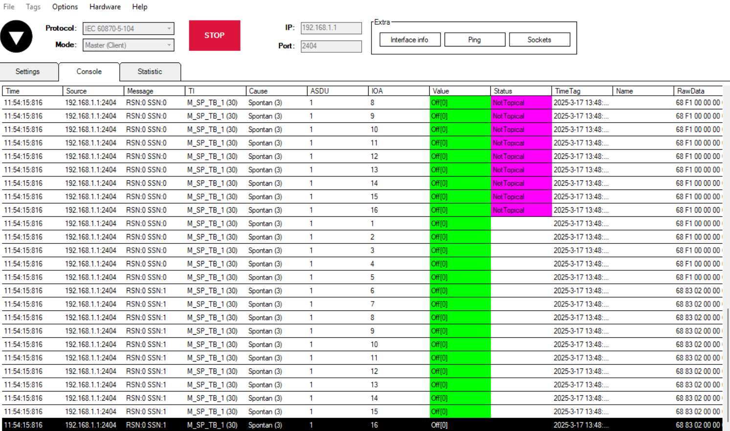
Once the IEC104 slave is connected, the console tab in Vinci software should look something like this:
If you want to configure IOMod 16DI, you should refer to -> IOMod 16DI User Manual.