18.3 Mathematical functions
The signal value might require some recalculation or signal update before being sent. Understandably, existing columns in Excel configuration like multiply, add, bit_select might not be flexible enough. To overcome these limitations, symbolic mathematical expressions can be configured to do calculations automatically on every update of a signal.
Feature list:
- Optimized for speed
- High parsing performance
- if-then-else operator with lazy evaluation
- Default implementation with many features
-
25 predefined functions
-
18 predefined operators
-
-
Unit support
-
Use postfix operators as unit multipliers (3m -> 0.003)
-
Mathematical functions
Table. Supported mathematical functions:
| Name | Argument count | Explanation |
| sin | 1 |
sine function (rad) |
| cos | 1 |
cosine function (rad) |
| tan | 1 |
tangent function (rad) |
| asin | 1 |
arcus sine function (rad) |
| acos | 1 |
arcus cosine function (rad) |
| atan | 1 |
arcus tangent function (rad) |
|
sinh |
1 |
hyperbolic sine function |
| cosh | 1 |
hyperbolic cosine |
| tanh | 1 |
hyperbolic tangent function |
| asinh | 1 |
hyperbolic arcus sine function |
| acosh | 1 |
hyperbolic arcus tangent function |
| atanh | 1 |
hyperbolic arcus tangent function |
| log2 | 1 |
logarithm to the base 2 |
| log10 | 1 |
logarithm to the base 10 |
| log | 1 |
logarithm to base e (2.71828...) |
| ln | 1 |
logarithm to base e (2.71828...) |
| exp | 1 |
e raised to the power of x |
| sqrt | 1 |
square root of a value |
| sign | 1 |
sign function -1 if x<0; 1 if x>0 |
| rint | 1 |
round to the nearest integer |
| abs | 1 |
absolute value |
| min | variable |
min of all arguments |
| max | variable |
max of all arguments |
| sum | variable |
the sum of all arguments |
| avg | variable |
the mean value of all arguments |
| floor | 1 |
round down to the nearest integer |
| mod | variable |
modulo operation |
It should be noted that trigonometric functions (excluding hyperbolic functions) only support arguments in radians. This means that arguments for this function have to be recalculated if the angle is defined in degrees.
Value recalculation is only triggered on signal change of the preconfigured signal. That means that using other signals (via TagValue() call) does not trigger a value update.
Some mathematical expressions cannot be mathematically evaluated in some conditions, for example, a square root cannot be found for negative numbers. As complex numbers are not supported, the result is then equal to Not a Number (NaN). These results are marked with an invalid (IV) flag.
Binary operations
Table. Supported binary operators:
| Operator | Description | Priority |
|
= |
assignment |
-1 |
|
» |
right shift |
0 |
|
« |
left shift |
0 |
|
& |
bitwise and |
0 |
|
| |
bitwise or |
0 |
|
&& |
logical and |
1 |
|
|| |
logical or |
2 |
|
<= |
less or equal |
4 |
|
>= |
greater or equal |
4 |
|
!= |
not equal |
4 |
|
== |
equal |
4 |
| > |
greater than |
4 |
| < |
less than |
4 |
| + |
addition |
5 |
| - |
subtraction |
5 |
| * |
multiplication |
6 |
| / |
division |
6 |
|
^ |
raise x to the power of y |
7 |
Ternary operators can be used. This expression can be compared to the operator supported by C/C++ language (Table 39). Condition is written before a question (?) sign. If the condition is true, the result after the question sign is selected. If the condition is false, the result after colon (:) is selected.
Ternary operations
Table. Supported ternary operators
| Operator | Description | Remarks |
|
?: |
if then else operator |
C++ style syntax |
Examples
Users can construct their equations by using the aforementioned operators and functions. These examples can be seen in the Table below.
Table. Example expressions
|
Expression |
Description |
|
value * 0.0001 |
Multiply the tag by a constant. |
|
value + TagValue(”tag/dev_alias/sig_alias/out”) |
Add value of tag/dev_alias/sig_alias/out to the current tag. |
|
sin(value) |
Return a predefined sine function value of the tag. |
|
(value>5)? 1: 0 |
If the value is greater than 5, the result should be equal to 1, otherwise - equal to 0 |
A variable called "value" is generated or updated on every signal change and represents the signals being configured. If another value from the tag list is intended to be used, one should use TagValue() function to retrieve its last value.
The inner argument of TagValue() function has to be described in a Redis topic structure of WCC Lite. That means that it has to be constructed in a certain way. Quotes should be used to feed the topic name value, otherwise expression evaluation will fail.
Every Redis topic name is constructed as tag/[device_alias]/[signal_alias]/[direction]. Prefix tag/ is always used before the rest of the argument. device_alias and signal_alias represent columns in Excel configuration. Direction can have one of four possible values - rout, out, in, rin; all of which depend on the direction data is sent or acquired device-wise. For example, the "out" keyword marks data sent out of the WCC Lite device, whereas the "in" direction represents data that WCC Lite is waiting to receive, for example, commands. Additional "r" before either direction means that data is raw, it is presented the way it was read by an individual protocol.
Signal mathematics
In this section, you will be shown how "math_expression" and other mathematical functions can be used in case of common signals. You can download the configuration to follow along here. Signals which we are concerned with in this section are highlighted in green colour.
Let us analyze what mathematical functions are configured for the signals. For both the second and third signals the same expression will be used: "value + TagValue(”tag/Master/RHR0/out”)". The only difference is that for the second signal scale function "add" was used.
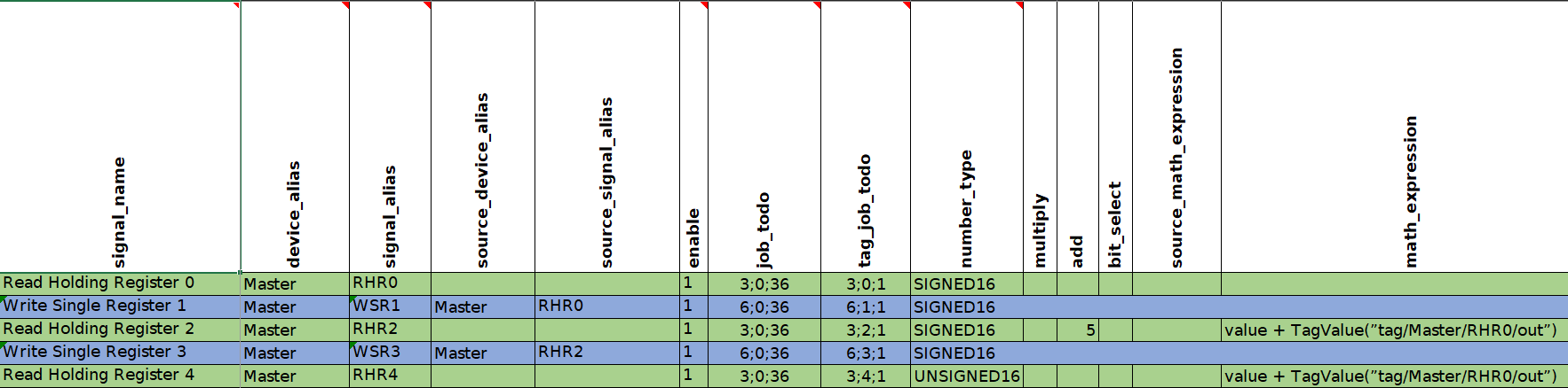
In this signal configuration, the value of the second signal is calculated by adding the current value of the second signal to the value of the first signal. Then the sum of two signals is going to be increased by 5. The third signal is going to be calculated in the same way except that 5 is not going to be added.
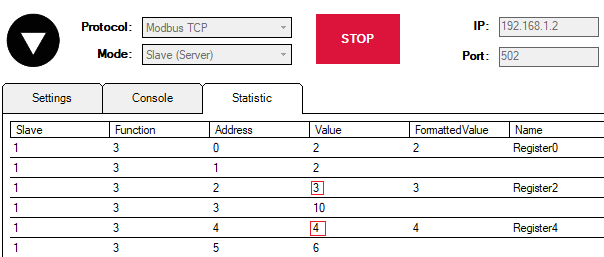
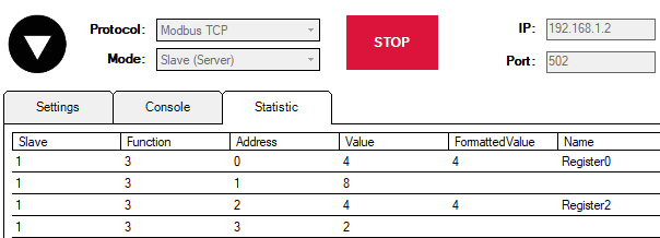
To see how it works let us start Modbus TCP Slave simulation in Vinci application. You can download the simulation here.
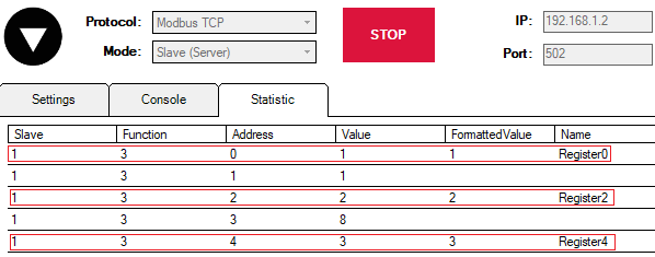
In the picture above you can see 6 registers. However, our main focus is null, second and fourth registers (Register0, Register2, Register4) since the first three signals of Modbus Master protocol (RHR0, RHR2 and RHR4) are reading the values of those registers (accordingly).
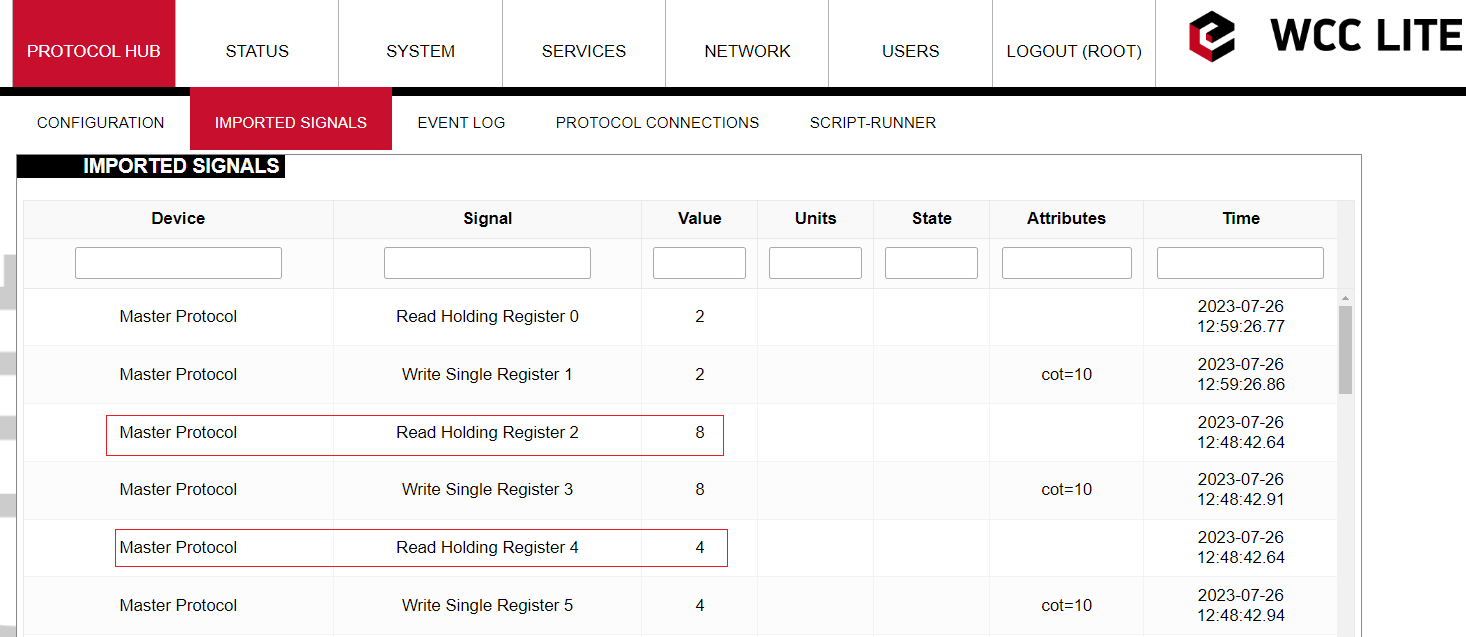
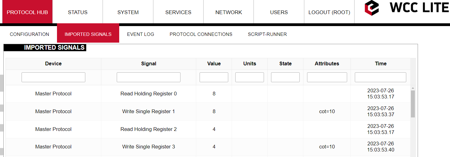
Let us go to the WCC Lite web interface to see how these signals are displayed there:
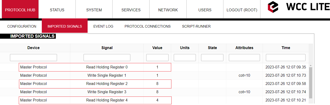
As we can see the values of the third and fifth signals have been modified (RHR2 = 2+1+5 = 8; RHR3 = 3+1 = 4). However, the values of the signals that are displayed in the web interface are intermediate so to speak. All the math is done in the protocol services (Modbus TCP Master in this case). Then those values are transmitted to the REDIS service. The values that are displayed in the web interface are REDIS values. We are going to see why it is important in another example.
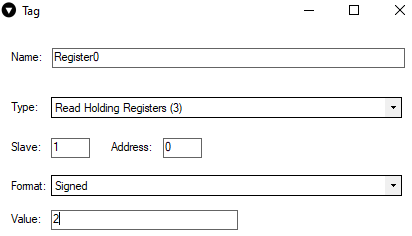
Now it was mentioned that the values of the third and fifth signals depend on the value of the first one. Let us see what will happen if we change the value of the Register 0. To do so we need to return to the VINCI application. Locate Register 0 and double-click on it. A menu with the register parameters will appear.
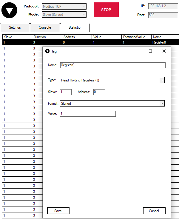
Now let us change the value of the register to 2:
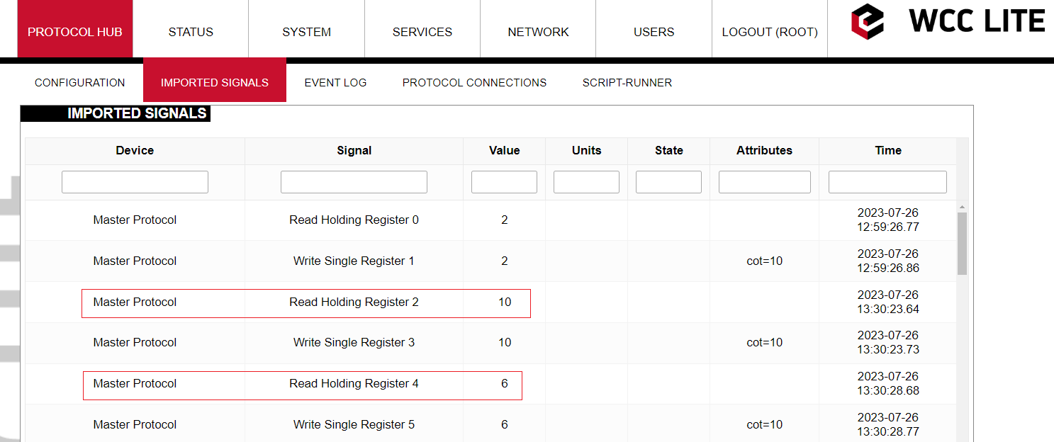
 Now it would be expected that the value of the second and third signals would become 9 and 5 accordingly (RHR2 = 2+2+5 = 9; RHR3 = 3+2 = 5). However if one checks the WCC Lite web interface right after that, one could notice that the second and third signals remained unchanged:
To explain this let us look again at the math expression of these signals. The equation (value + TagValue(”tag/Master/RHR0/out”)) consists of two operands "value" and "TagValue(”tag/Master/RHR0/out”)". Currently, the system is designed in such a way that only if the "value" operand has changed, only then there is going to be a change in a signal's value. So if the values of the second and fourth registers are changed (increased by one in this example) then the values of the third and fifth signals are going to change taking into account the previous change in the value of Register 0 (RHR2 = 2+3+5 = 10; RHR3 = 2+4 = 6).
Command mathematics
In this section, you will be shown how "math_expression", and other mathematical functions can be used in case of command signals. You can download the configuration to follow along here. Signals which we are concerned with in this section are highlighted in blue colour.
Let us analyze what mathematical functions are configured for the signals.
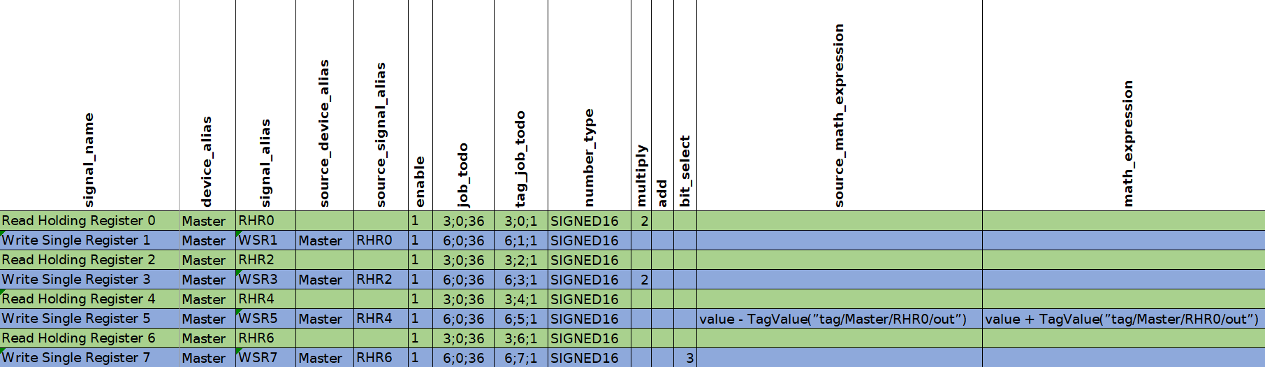
The first four signals are going to be used for scale function analysis. To see how it works let us start Modbus TCP Slave simulation in Vinci application. You can download the simulation here.
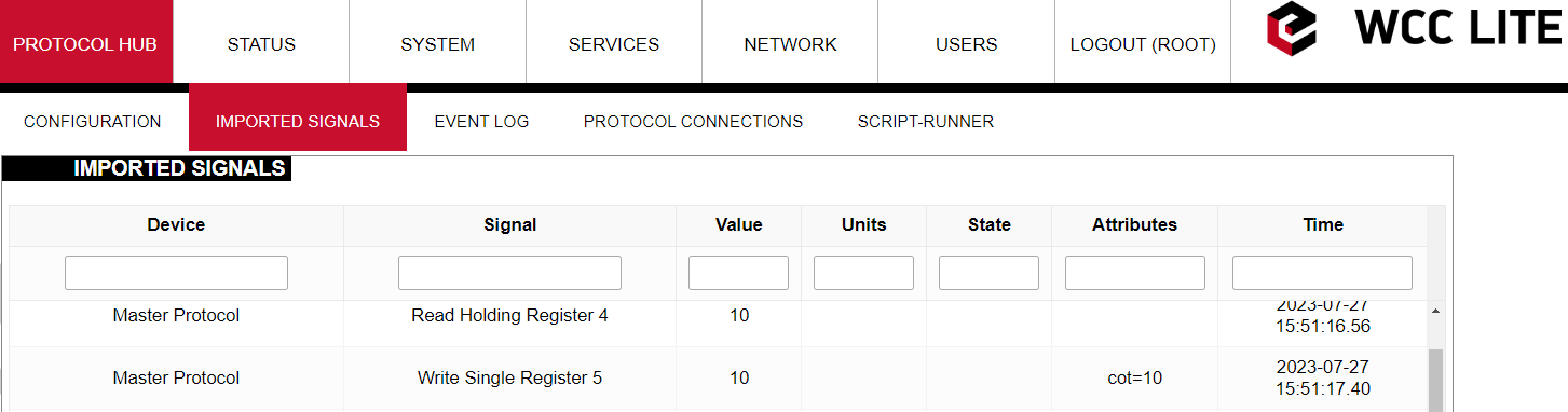
Let us go to the WCC Lite web interface to see how these signals are displayed there:
As one can notice the values displayed in the Vinci application differ from the values displayed in the web interface. To better understand the results let us see step by step how signals are modified.
The first signal RHR0 reads the value of Register 0 which is equal to 4. After the read operation, the value is multiplied by two in the master protocol service. Then the signal is transmitted to the REDIS service. REDIS value is presented in the web interface. Then the same value 8 is written to Register 1 by sending a WSR1 command signal. Finally, the value of the WSR1 signal is displayed in the Vinci simulation.
The third signal RHR2 behaves quite the same as the first RHR0 signal. It reads the value of Register 2 and without performing any scaling operations transmits value to REDIS. It again can be seen in the web interface. While still in REDIS service the value of Register 2 is passed to WSR3 signal. Then command signal WSR3 is transmitted back to the Modbus Master protocol service where the value of the signal is scaled. One could expect that the value of the signal would be multiplied by two but it is divided by two. Then the value of 2 is displayed in the Vinci Slave simulation. After changing the value of Register 3 WSR3 signal is sent back from the Master Protocol service to REDIS. On its way, the signal again passes the signal scaling place where it is again multiplied by two. This is why we see in the web interface that the value of the fourth signal WSR3 is 4.
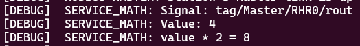
All the moments when a signal passes a place where its value is scaled can be seen by turning on a debugger session. To do so one should connect to WCC Lite via Ubuntu terminal in Terminal application. Then Modbus Master protocol needs to be stopped by sending "/etc/init.d/modbus-master stop". Then Modbus Master protocol needs to be started again with the -m flag (m for math) "modbus-master -d7 -m -c /etc/modbus-master/modbus-tcp.json".

If you scroll up after starting the session you will be able to find how both RHR0 and WSR3 signals are scaled after passing the signal scaling place.
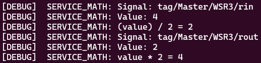
Why is it the case that the signal is divided instead of being multiplied by two? The answer to this question is that the scaling factor depends on the direction of the signal. When the RHR0 signal was travelling from Master Protocol to REDIS service and was passing the place where signals are scaled the signal was multiplied by a scaling factor. On the other hand, when the WSR3 signal was travelling from REDIS service to Master Protocol and was passing the same signal scaling place the signal was divided by the scaling factor.
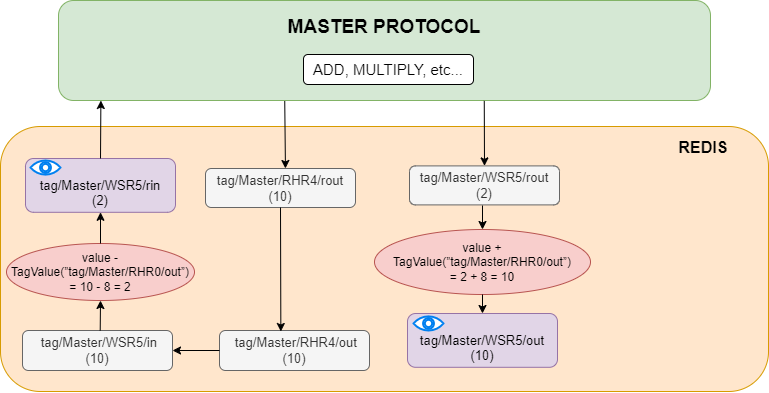
Now let us analyze how "math_expression" and "source_math_expression" are applied to the WSR5 signal. To get a better insight let us look at how signals are transmitted and transformed inside WCC Lite and when mathematical expressions are applied.
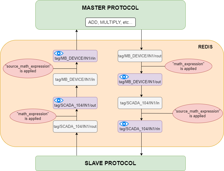
Let us analyze the diagram above. As we can see all basic mathematical operations (such as add, multiply, etc.) are performed inside a Master protocol service. When signals are transmitted between protocols they travel through REDIS service. The period of existence of a signal inside the REDIS service can be divided into four stages. They can be denoted by their endings, namely: "rout", "out", "in" and "rin". At the "out" and "rin" stages signal values can be seen through certain interfaces which is why they are displayed in a purple colour with blue eyes on them. At the "out" stage a signal is displayed on the WCC Lite web interface, at the "rin" stage signal value can be seen through the Vinci application. As one can notice "math_expression" is applied before the "out" stage and "source_math_expression" is performed before the "rin" stage.
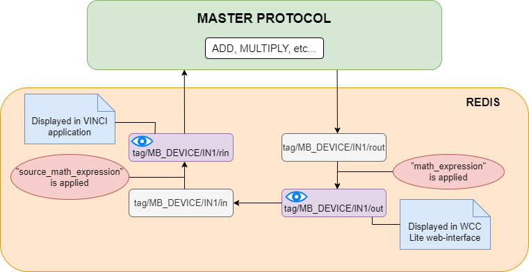
However, in our particular example, we did not configure any Slave device. In this situation signal transportation inside REDIS service can be depicted as follows:
Let us return to our example and let us see what are the values of the WSR5 signal in the WCC Lite web interface and Vinci Slave simulation.
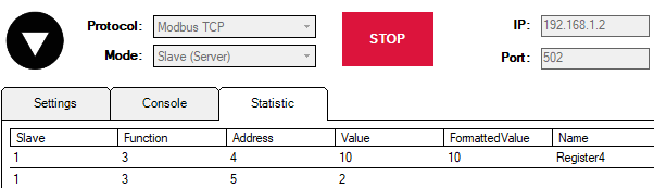
The diagram below explains how these values were calculated.
Extra functions
Several functions are defined to make tag operations possible:
TagValue(key)- returns the last known value of the tag identified by the Redis key;TagFlag(key)- returns 1 if the tag flag exists. The name format is: ”key flag”. For example, to check if the tag is non-topical, the name would be ”tag/19xxxxxxx/x/x nt”;TagAttribute(key)- similar to TagFlag, but returns a numeric value of a tag attribute;TagTime(key)- returns the UNIX timestamp in milliseconds of the last known tag value.