8.7 Network
The page shows information about the current interface status, and its configurations, provides various interface, and network properties configuration capabilities and contains the following subsections:
• INTERFACES: shows information about current interface status, and allows for creating and configuring new ones.
• WIRELESS: shows information about wireless radio stations, and covers the physical settings of the wireless hardware.
• DHCP AND DNS: allows management of DHCP and DNS servers.
• HOSTNAMES: allows management of host names.
• STATIC ROUTES: allows management of IPv4 and IPv6 static routes.
• FIREWALL: allows management of firewall zones and various firewall properties.
• DIAGNOSTICS: provides network diagnostics utilities.
• GSM: allows management of GSM modem and SIM cards.
Interfaces
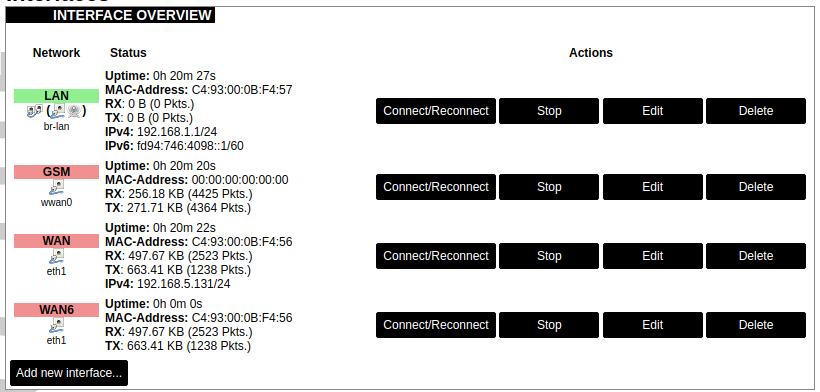
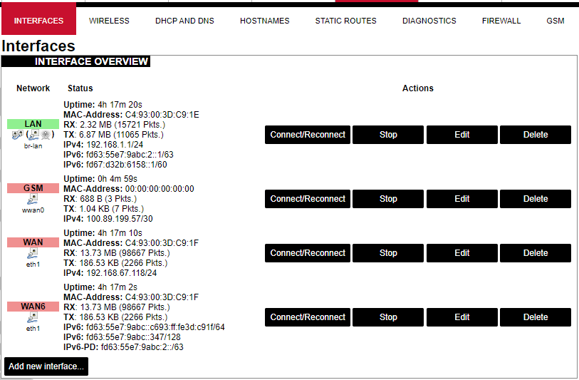
Current information and status of various network interfaces (GSM, LAN, WAN).
Uptime: The current interface uptime in hours, minutes and seconds.
MAC address: Physical interface address.
RX: Received data in bytes (packet count).
TX: Transmitted data in bytes (packet count).
IPv4: Internet protocol version 4 address.
IPv6: Internet protocol version 6 address.
In addition to the network interface status, several actions may be performed:
Connect/Reconnect: Connect to the configured interface network if it does not do it automatically. If it is already connected to the network it will be trying to reconnect to it.
Stop: Shutdown interface. If you are connected through this interface the connection may be lost.
Edit: Edit interface settings.
Delete: Delete interface.
Add new interface: Adding new Ethernet, GSM or wireless interface with the custom name, protocol, etc.
| eth0 | eth1 | |
| Type | Static | DHCP |
| Address | 192.168.1.1 | |
| Subnet mask | 255.255.255.0 | |
| Gateway |
Changes will only take effect after the device reboots.
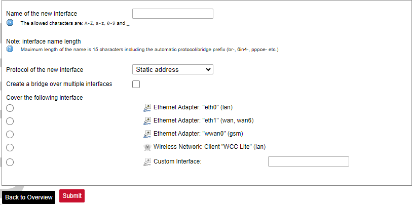
Network interfaces can be configured on the common page, which can be accessed through adding a new interface or an edit button.
The following options can be defined in the interface creation panel: name of the interface, protocol, coverage of a particular interface or bridging with other interfaces. After the general setup is done, more detailed settings can be set.
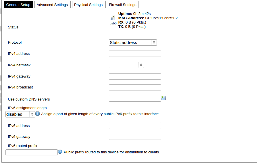
General common interface setup panel.
Advanced common interface setup panel.
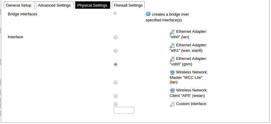
Physical common interface setup panel.
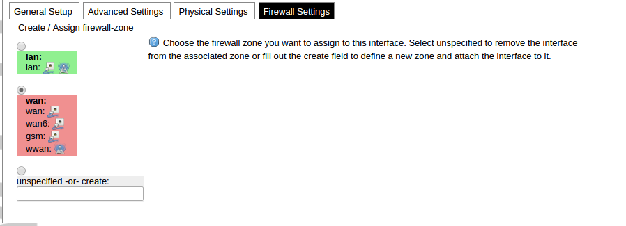
Firewall common interface setup panel.
DHCP server general setup panel.
DHCP server advanced setup panel.
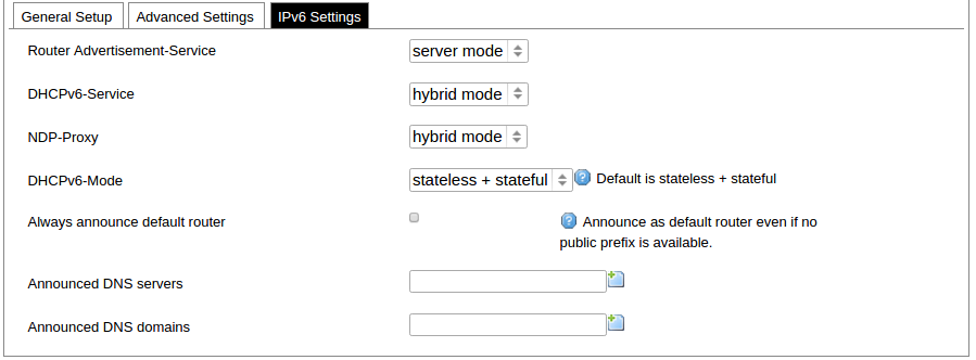
DHCP server IPv6 settings setup panel.
GSM
General Settings Information tab. Gives you the name of the physical GSM interface, and lets you choose the protocol (not recommended!).
Note: Make sure you won’t change the GSM interface's protocol, which is set by default to WWAN. Changing this parameter will lead to undefined GSM modem behaviour.
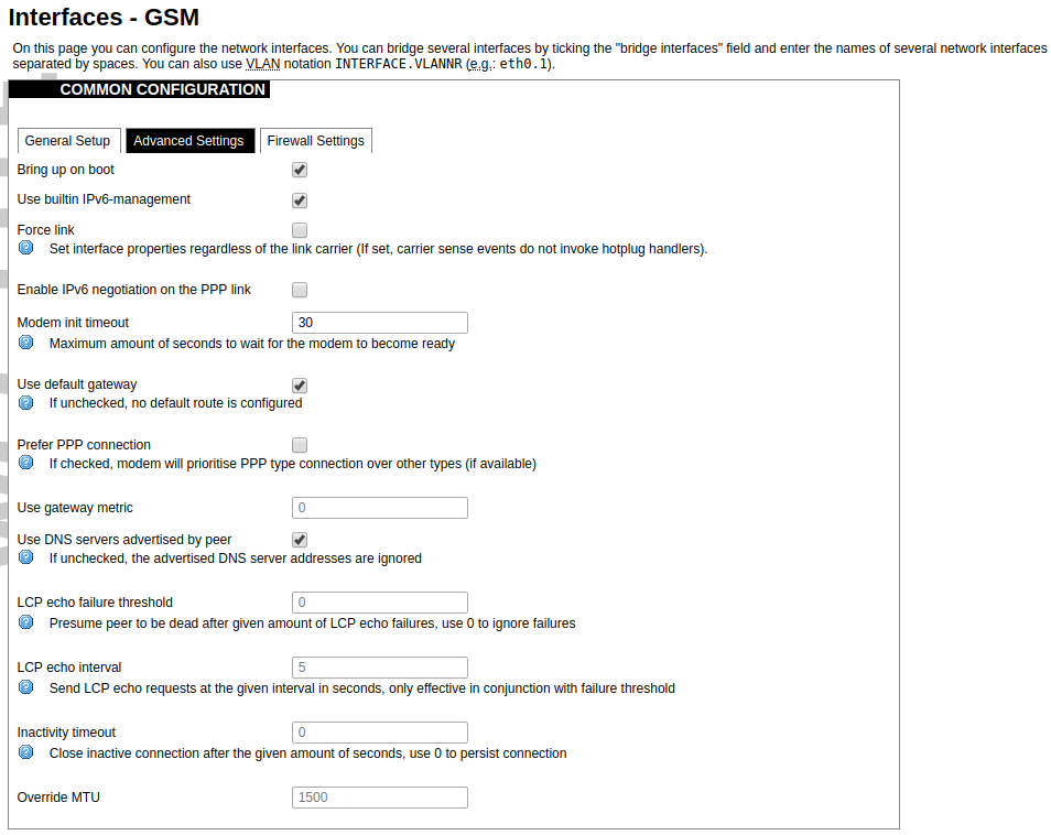
Advanced Settings tab enables users to configure advanced settings for mobile communication. It includes the following options:
Bring up on boot: Checkbox to start a GSM interface on startup;
Use built-in IPv6-management: Checkbox to select if the device is going to use its tools to manage IPv6 transport layer messages;
Force link: Specifies whether IP address, route, and gateway are assigned to the interface regardless of whether the link is active or only after the link has become active; when active, carrier sense events do not invoke hotplug handlers;
IPv6 support: The user can select if IPv6 support is handled automatically, manually or disabled altogether;
Modem init timeout: Maximum amount of seconds before the device gives up on finishing initialization;
Use default gateway: Uses the default gateway obtained through DHCP. If left unchecked, no default route is configured;
Prefer PPP connection: If, the modem, supports PPP and any other communication protocol (e.g. QMI, RNDIS etc.), prioritize PPP type connection;
Use gateway metric: The WAN configuration by default generates a routing table entry. In this field, you can alter the metric of that entry. Higher metric means higher priority;
Use DNS servers advertised by peer: Uses DNS servers obtained from DHCP. If left unchecked, the advertised DNS server addresses are ignored;
LCP echo failure threshold: LCP (link control protocol) is a part of PPP (Point-to-Point Protocol) and helps to determine the quality of data transmission. If enough failures happen, LCP presumes the link to be dead. 0 disables failure count checking;
LCP echo interval: Determines the period of LCP echo requests. Only effective if the LCP echo failure threshold is more than zero;
Inactivity timeout: Station inactivity limit in seconds: if a station does not send anything, the connection will be dropped. A value of 0 can be used to persist the connection.
Override MTU: Set custom MTU to GSM interface.
Note: If the modem uses QMI connection protocol and the user hasn’t defined a custom MTU setting, the MTU on the interface will be set to the operator’s defined MTU value.
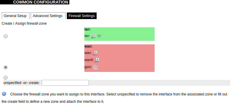
GSM configuration ends with firewall settings. A user can assign an already-defined firewall zone or create a new one.
Wireless
The wireless network interface parameters and configuration are described in this section.
Configured interfaces for the physical radio device.
Channel: Specifies the wireless channel to use.
Bitrate: Specifies transfer rate in Mbit/s.
SSID: The broadcasted service set identifier of the wireless network.
Mode: Select the operation mode of the wireless network interface controller.
BSSID: The basic service set identification of the network, only applicable in ad-hoc or STA mode.
Encryption: Wireless encryption method.
List of associated wireless stations.
The Device Configuration section covers the physical settings of the radio hardware such as channel, transmit power or antenna selection which are shared among all defined wireless networks (if the radio hardware is multi-SSID capable). Network settings like encryption or operation mode are grouped in the Interface Configuration.
General device settings.
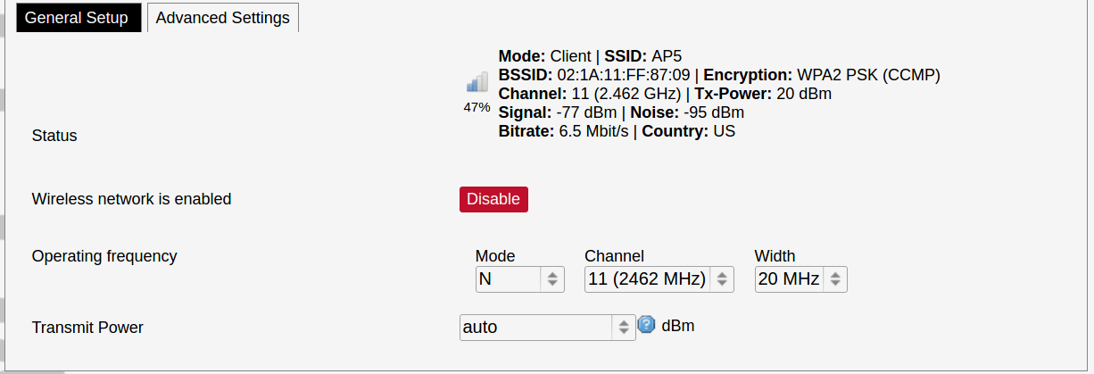
Advanced device settings.
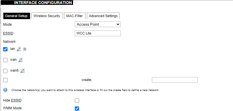
General interface settings.
Wireless security interface settings.
MAC-Filter settings.
Advanced interface settings.
DHCP and DNS
DHCP server and DNS forward for NAT firewalls are described in this section.
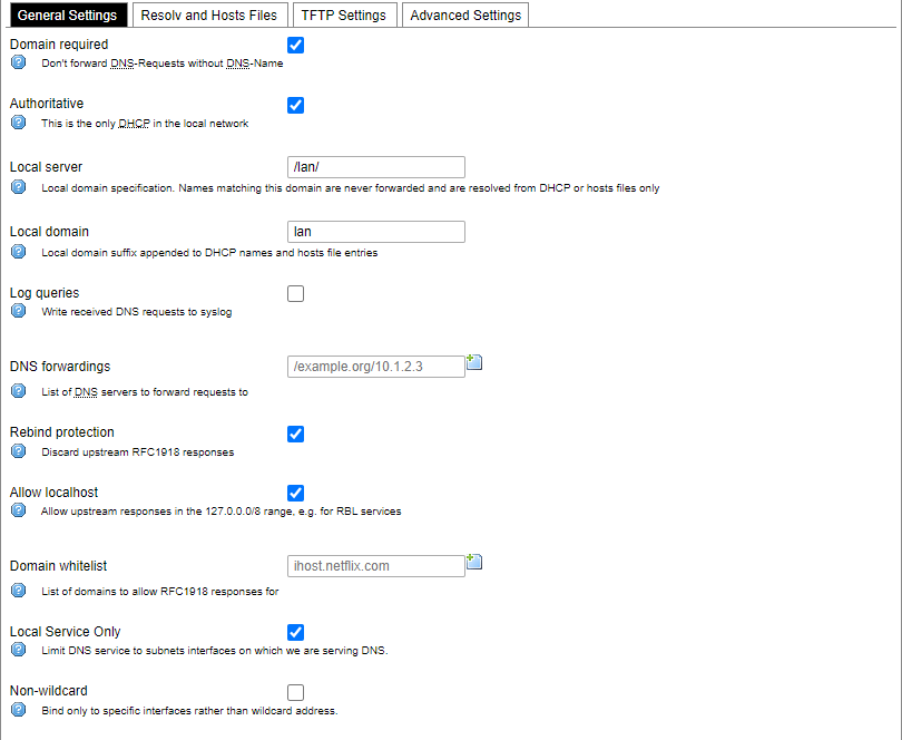
General DHCP settings.
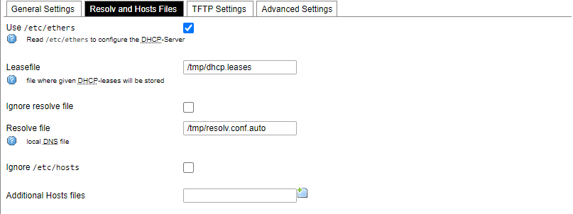
Resolve and host file settings.
TFTP server settings.
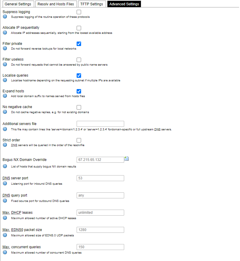
Advanced settings.
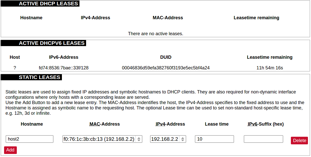
List of active DHCP and static leases. It is also possible to assign fixed IP addresses to hosts on the network, based on their MAC (hardware) address.
Hostnames
List of existing host names. Addition or deletion is allowed for the user.
Static routes
Routes specify over which interface and gateway a certain host or network can be reached.
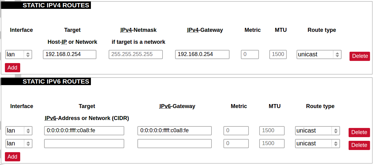
Current IPv4 and IPv6 static routes configuration.
Interface: Let to choose for which interface static route is created.
Target: Defines target host IP or network.
IPv4 Netmask: Defines netmask if the target is a network.
IPv4/IPv6 Gateway: Defines IPv4 or IPv6 gateway.
Metric: Specifies the route metric to use for the route.
MTU: Maximum Transmit/Receive Unit, in bytes.
Route type: All incoming packets can be: accepted, rejected, or dropped.
Diagnostics
Diagnostics tools which can be used to diagnose some of the networking problems: ping, traceroute and nslookup.
Firewall
This subsection is divided into four categories: general settings, port forwards, traffic rules and custom rules.
General settings
General firewall settings can be changed in the General Settings screen. These settings are defined as follows:
Input: All incoming packets can be: accepted, rejected, or dropped.
Output: All outgoing packets can be: accepted, rejected, or dropped.
Forward: All packets being sent to another device can be: accepted, rejected, or dropped.
Additional zones for the firewall can be created, edited or deleted.
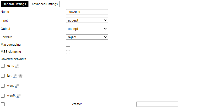
Zone => Forwardings: Defines zones and their traffic flow.
Input: All incoming packets can be: accepted, rejected, or dropped.
Output: All outgoing packets can be: accepted, rejected, or dropped.
Forward: All packets being sent to another device can be: accepted, rejected, or dropped.
Masquerading: Allows one or more devices in a zone network without assigned IP addresses to communicate with the Internet.
MSS clamping: Change the maximum segment size (MSS) of all TCP connections passing through this zone with MTU lower than the Ethernet default of 1500.
Additional actions can be performed with zones: add, edit, delete.
Common properties of newly created or edited zones can be edited in this panel. The input and output options set the default policies for traffic entering and leaving this zone while the forward option describes the policy for forwarded traffic between different networks within the zone. Covered networks specify which available networks are members of this zone.
Advanced settings of newly created or edited zones. Restrict to address family option defines to what IP families the zone belongs to IPv4, IPv6 or both. Restrict masquerading to given source/destination subnets defines one or more subnets for which the masquerading option is applied. Connection tracking and logging options enable additional information gathering on the zone.
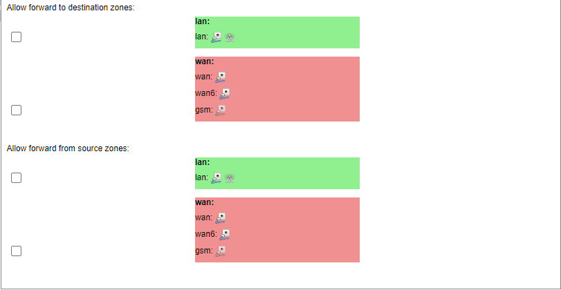
Controls the forwarding policies between new/edited zone and other zones. Destination zones cover forwarded traffic originating from the new/edited zone. Source zones match forwarded traffic from other zones targeted at the new/edited zone. The forwarding rule is unidirectional, e.g. a forward from LAN to WAN does not imply permission to forward from WAN to LAN as well.
Port forwards
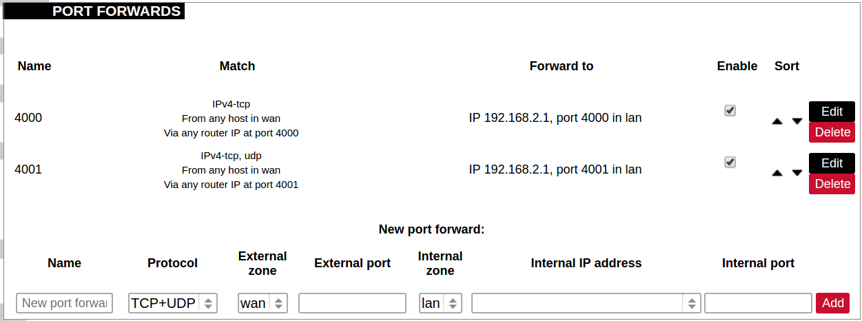
Port forwarding allows remote computers on the Internet to connect to a specific computer or service within the private LAN. It is done in a way of routing network packets within a private network created by the device. Settings for the port forwarding of the device are defined as follows:
Name: The name of the port forwarding rule.
Match: Informs what port forward is matched to.
Forward to: Informs where the port is forwarded to.
Enable: Enable (checked) or disable port forward.
Sort: Allows to sort port forwarding.
The user can add, edit or delete port forwarding rules.
Traffic rules
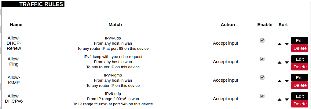
Traffic rules define policies for packets travelling between different zones.
Name: The name of the traffic rule.
Match: Informs what ICMP types are matched.
Action: Informs what action would be performed.
Enable: Enable (checked) or disable the rule.
Sort: Allows to sort rules.
The user can add, edit or delete traffic rules. Every rule can be defined by these options: name, restrict to address family, protocol, match ICMP type, source and destination zones, source MAC, IP addresses and port, destination IP address and port, action and extra arguments, month and weekdays for which rule will apply, start/stop dates and times, time in UTC.
Source NAT is a specific form of masquerading which allows fine-grained control over the source IP used for outgoing traffic, for example, to map multiple WAN addresses to internal subnets.
The user can add, edit or delete source NAT rules. For every rule can be defined these options: name, protocol, source and destination zones, source, destination, SNAT IP addresses, ports, extra arguments, month and weekdays for which rule will apply, start/stop dates and times, time in UTC.
Custom rules
Custom rules allow the execution of arbitrary iptables commands which are not otherwise covered by the firewall framework. The commands are executed after each firewall restart, right after the default ruleset has been loaded.
GSM
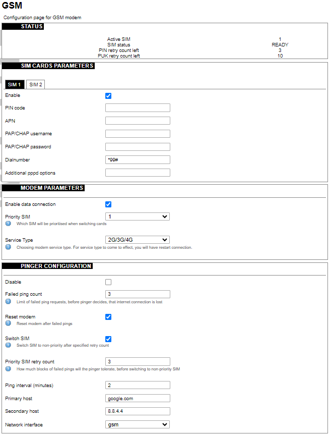
Gsm settings
Note: If you have a WCC Lite without a modem, the GSM tab will still be visible, but these changes won't affect anything.
Note: From FW version 1.9.1 Pinger is disabled by default.
SIM cards parameters
Parameters for SIM card. If a single SIM modem is used, there won’t be ”SIM 1” and ”SIM 2” tabs.
Enable: Enable or disable this SIM card.
PIN code: PIN code to use on that SIM card.
APN: APN to use on that SIM car.
PAP/CHAP username: Username (optional).
PAP/CHAP password: Password (optional).
Modem parameters
Enable data connection: Enable or disable data connection through a GSM modem.
Priority SIM: Primary SIM card (if Dual SIM modem is used). Mainly used for pinger configuration.
Service Type: Which radio access technology will be used when connecting to the GSM network. Each modem has different available preset RAT options, that can be selected in the drop-down menu.
Pinger configuration
Pinger is a service which pings defined hosts to check internet connection. If both of these hosts are unreachable pinger will wait and restart the modem (or switch SIM card, if Dual-SIM modem is installed in WCC Lite)
Disable: Disable pinger functionality.
Failed ping count: Limit of failed ping requests, before the pinger decides that the internet connection is lost.
Reset modem: If checked, pinger resets the gsm modem after ”Failed ping count”.
Switch SIM: If checked, pinger switches SIM to non-priority after ”Priority SIM retry count”. If an internet connection is not available with a non-priority SIM as well, the pinger switches back to a priority SIM after one failed ping attempt.
Priority SIM retry count: How many blocks of failed pings will the pinger tolerate, before switching to non-priority SIM.
Ping interval (minutes): Interval between ping requests.
Primary host: The host that will be pinged first.
Secondary host: The host that will be pinged second, if the primary host fails.
Network interface: GSM network interface name.
GSM Pinger is used to detect the status of network connections via cellular networks. This status is written to file (/var/run/board/internet-status) and can be configured to be sent to SCADAs. If the pinger is disabled, the status is always set equal to zero and should not be trusted to represent internet status. Additionally, this status is reflected in the ”Status”-> “GSM Status” window.
This is Pinger functionality described step by step:
• Pinger will ping the primary host every 2 minutes.
• If the primary host fails, the pinger redirects to the secondary host immediately.
• If either the primary or secondary host is responding to ping requests, the pinger will continue testing the connection with every ”Ping interval (minutes)” parameter and no further action is taken.
• If both primary and secondary hosts are unreachable, the pinger will start pinging these hosts every ”Ping interval (minutes) / 2” minute for ”Failed ping count” times.
• If hosts are still unreachable, the pinger will try to switch SIM and restart the modem (if corresponding parameters are set) or will restart immediately if a single SIM modem is used.
• SIM card is switched to non-priority SIM after ”Priority SIM retry count” failed modem restarts with priority SIM. If a non-priority SIM fails, it is switched to a priority SIM in the next pinger action.
Dual SIM start procedure
The table below shows, which card is expected on boot when a selection is made between Enable/Disable SIM cards and Primary card.
| SIM 1 Enabled | SIM 2 Enabled | Priority SIM | SIM on boot |
| X | 1 | 1 | |
| X | 2 | 1 | |
| X | 1 | 2 | |
| X | 2 | 2 | |
| X | X | 1 | 1 |
| X | X | 2 | 2 |
| 1 | Undefined | ||
| 2 | Undefined |
SMS Log
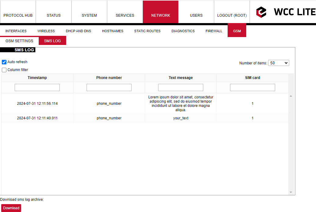
SMS logging is available from firmware version 1.9.1
Here the user can find all the messages that were sent to the device. It shows the time that the message was received, the sender's phone number and the text sent. The SIM card column shows to which SIM card (1 or 2) was the message sent.
Layer 2 Tunneling Protocol
In computer networking, Layer 2 Tunneling Protocol (L2TP) is a tunnelling protocol used to support virtual private networks (VPNs) or as part of the delivery of services by ISPs. It does not provide any encryption or confidentiality by itself. Rather, it relies on an encryption protocol that it passes within the tunnel to provide privacy.
Description
The entire L2TP packet, including payload and L2TP header, is sent within a User Datagram Protocol (UDP) datagram. It is common to carry PPP sessions within an L2TP tunnel. L2TP does not provide confidentiality or strong authentication by itself. IPsec is often used to secure L2TP packets by providing confidentiality, authentication and integrity. The combination of these two protocols is generally known as L2TP/IPsec (discussed below). The two endpoints of an L2TP tunnel are called the LAC (L2TP Access Concentrator) and the LNS (L2TP Network Server). The LNS waits for new tunnels. Once a tunnel is established, the network traffic between the peers is bidirectional. To be useful for networking, higher-level protocols are then run through the L2TP tunnel. To facilitate this, an L2TP session (or ’call’) is established within the tunnel for each higher-level protocol such as PPP. Either the LAC or LNS may initiate sessions. The traffic for each session is isolated by L2TP, so it is possible to set up multiple virtual networks across a single tunnel. MTU should be considered when implementing L2TP. The packets exchanged within an L2TP tunnel are categorized as either control packets or data packets. L2TP provides reliability features for the control packets, but no reliability for data packets. Reliability, if desired, must be provided by the nested protocols running within each session of the L2TP tunnel. L2TP allows the creation of a virtual private dialup network (VPDN) to connect a remote client to its corporate network by using a shared infrastructure, which could be the Internet or a service provider’s network.
Setting up the L2TP interface
To create an L2TP tunnel following steps are required:
1. Go to Network > Interfaces > Add new interface:
2. Enter the interface name and select L2TP protocol:
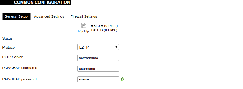
3. Enter the server name and authorization parameters:
4. Save and apply the new configuration. A new network interface will appear.


