IEC 60870-5-101
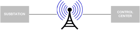
IEC 60870-5-101 is a protocol for power system monitoring and controlling. Mostly used for communication between substations and control centers over radio.
Info about protocol
Telegram Structure
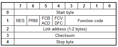
Teleram format with fixed length
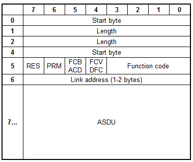
Telegram format with variable length
- RES - Reserved
- PRM - 1 if master, 0 if slave
PRM = 1
- FCB - alternating bit for successive services per station
- FCV - (if FCV=1 FCB enabled)
PRM = 0
- ACD - access demand (if ACD=1 there are class 1 data)
- DFC - data flow control (if DFC=1 further messages may cause data overflow)
ASDU - Application Service Data Unit
Function Code
PRM=1
|
Dec |
Frame type |
Service function |
FCV |
|
0 |
SEND/CONFIRM expected |
Reset of remote link |
0 |
|
1 |
SEND/CONFIRM expected |
Reset of user process |
0 |
|
2 |
SEND/CONFIRM expected |
Reserved |
- |
|
3 |
SEND/CONFIRM expected |
User data |
1 |
|
4 |
SEND/REPLY expected |
User data |
0 |
|
5 |
|
Reserved |
- |
|
6 |
|
Reserved |
- |
|
7 |
|
Reserved |
- |
|
8 |
REQUEST for access demand |
Expected response specifies access demand |
0 |
|
9 |
REQUEST/RESPOND expected |
Request status of link |
0 |
|
10 |
REQUEST/RESPOND expected |
Request user data class 1 |
1 |
|
11 |
REQUEST/RESPOND expected |
Request user data class 2 |
1 |
|
12 |
|
Reserved |
- |
|
13 |
|
Reserved |
- |
|
14 |
|
Reserved |
- |
|
15 |
|
Reserved |
- |
PRM=0
|
Dec |
Frame type |
Service function |
|
0 |
CONFIRM |
ACK: positive acknowledgment |
|
1 |
CONFIRM |
NACK: message not accepted, link busy |
|
2 |
|
Reserved |
|
3 |
|
Reserved |
|
4 |
|
Reserved |
|
5 |
|
Reserved |
|
6 |
|
Reserved |
|
7 |
|
Reserved |
|
8 |
RESPOND |
User data |
|
9 |
RESPOND |
Requested data not available |
|
10 |
|
Reserved |
|
11 |
RESPOND |
Status of link |
|
12 |
|
Reserved |
|
13 |
|
Reserved |
|
14 |
|
Reserved |
|
15 |
|
Reserved |
Type identification
Standard IEC 60870-5-101 data types[1-255]
•[1-127] - standard definition
•[128-135] - reserved for routing of messages
•[136-255] - for special use
|
Dec |
Type |
Description |
Direction |
Support |
|
Process information |
||||
|
1 |
M_SP_NA_1 |
Single-point information |
Monitor |
Yes |
|
2 |
M_SP_TA_1 |
Single-point information with time tag |
Monitor |
Yes |
|
3 |
M_DP_NA_1 |
Double-point information |
Monitor |
Yes |
|
4 |
M_DP_TA_1 |
Double-point information with time tag |
Monitor |
Yes |
|
5 |
M_ST_NA_1 |
Step position information |
Monitor |
Yes |
|
6 |
M_ST_TA_1 |
Step position information with time tag |
Monitor |
Yes |
|
7 |
M_BO_NA_1 |
Bit string of 32 bit |
Monitor |
Yes |
|
8 |
M_BO_TA_1 |
Bit string of 32 bit with time tag |
Monitor |
Yes |
|
9 |
M_ME_NA_1 |
Measured value, normalized value |
Monitor |
Yes |
|
10 |
M_ME_TA_1 |
Measured value, normalized value with time tag |
Monitor |
Yes |
|
11 |
M_ME_NB_1 |
Measured value, scaled value |
Monitor |
Yes |
|
12 |
M_ME_TB_1 |
Measured value, scaled value wit time tag |
Monitor |
Yes |
|
13 |
M_ME_NC_1 |
Measured value, short floating point number |
Monitor |
Yes |
|
14 |
M_ME_TC_1 |
Measured value, short floating point number with time tag |
Monitor |
Yes |
|
15 |
M_IT_NA_1 |
Integrated totals |
Monitor |
Yes |
|
16 |
M_IT_TA_1 |
Integrated totals with time tag |
Monitor |
Yes |
|
17 |
M_EP_TA_1 |
Event of protection equipment with time tag |
Monitor |
Yes |
|
18 |
M_EP_TB_1 |
Packed start events of protection equipment with time tag |
Monitor |
Yes |
|
19 |
M_EP_TC_1 |
Packed output circuit information of protection equipment with time tag |
Monitor |
Yes |
|
20 |
M_PS_NA_1 |
Packed single point information with status change detection |
Monitor |
Yes |
|
21 |
M_ME_ND_1 |
Measured value, normalized value without quality descriptor |
Monitor |
Yes |
|
30 |
M_SP_TB_1 |
Single-point information with time tag CP56Time2a |
Monitor |
Yes |
|
31 |
M_DP_TB_1 |
Double-point information with time tag CP56Time2a |
Monitor |
Yes |
|
32 |
M_ST_TB_1 |
Step position information with time tag CP56Time2a |
Monitor |
Yes |
|
33 |
M_BO_TB_1 |
Bit string of 32 bit with time tag CP56Time2a |
Monitor |
Yes |
|
34 |
M_ME_TD_1 |
Measured value, normalized value with time tag CP56Time2a |
Monitor |
Yes |
|
35 |
M_ME_TE_1 |
Measured value, scaled value with time tag CP56Time2a |
Monitor |
Yes |
|
36 |
M_ME_TF_1 |
Measured value, short floating point number with time tag CP56Time2a |
Monitor |
Yes |
|
37 |
M_IT_TB_1 |
Integrated totals with time tag CP56Time2a |
Monitor |
Yes |
|
38 |
M_EP_TD_1 |
Event of protection equipment with time tag CP56Time2a |
Monitor |
Yes |
|
39 |
M_EP_TE_1 |
Packed start events of protection equipment with time tag CP56Time2a |
Monitor |
Yes |
|
40 |
M_EP_TF_1 |
Packed output circuit information of protection equipment with time tag CP56Time2a |
Monitor |
Yes |
|
45 |
C_SC_NA_1 |
Single command |
Control |
Yes |
|
46 |
C_DC_NA_1 |
Double command |
Control |
Yes |
|
47 |
C_RC_NA_1 |
Regulating step command |
Control |
Yes |
|
48 |
C_SE_NA_1 |
Set-point Command, normalized value |
Control |
Yes |
|
49 |
C_SE_NB_1 |
Set-point Command, scaled value |
Control |
Yes |
|
50 |
C_SE_NC_1 |
Set-point Command, short floating point number |
Control |
Yes |
|
51 |
C_BO_NA_1 |
Bit string 32 bit command |
Control |
Yes |
|
58 |
C_SC_TA_1 |
Single command with time tag CP56Time2a |
Control |
Yes |
|
59 |
C_DC_TA_1 |
Double command with time tag CP56Time2a |
Control |
Yes |
|
60 |
C_RC_TA_1 |
Regulating step command with time tag CP56Time2a |
Control |
Yes |
|
61 |
C_SE_TA_1 |
Measured value, normalized value command with time tag CP56Time2a |
Control |
Yes |
|
62 |
C_SE_TB_1 |
Measured value, scaled value command with time tag CP56Time2a |
Control |
Yes |
|
63 |
C_SE_TC_1 |
Measured value, short floating point number command with time tag CP56Time2a |
Control |
Yes |
|
64 |
C_BO_TA_1 |
Bit string of 32 bit command with time tag CP56Time2a |
Control |
Yes |
|
System information |
||||
|
70 |
M_EI_NA_1 |
End of Initialization |
Monitor |
Yes |
|
100 |
C_IC_NA_1 |
Interrogation command |
Control |
Yes |
|
101 |
C_CI_NA_1 |
Counter interrogation command |
Control |
Yes |
|
102 |
C_RD_NA_1 |
Read command |
Control |
Yes |
|
103 |
C_CS_NA_1 |
Clock synchronization command |
Control |
Yes |
|
104 |
C_TS_NA_1 |
Test command |
Control |
Yes |
|
105 |
C_RP_NA_1 |
Reset process command |
Control |
Yes |
|
106 |
C_CD_NA_1 |
Delay acquisition command |
Control |
No |
|
107 |
C_TS_TA_1 |
Test command with time tag CP56Time2a |
Control |
No |
|
Parameter |
||||
|
110 |
P_ME_NA_1 |
Parameter of measured values, normalized value |
Control |
No |
|
111 |
P_ME_NB_1 |
Parameter of measured values, scaled value |
Control |
No |
|
112 |
P_ME_NC_1 |
Parameter of measured values, short floating point number |
Control |
No |
|
113 |
P_AC_NA_1 |
Parameter activation |
Control |
No |
|
File transfer |
||||
|
120 |
F_FR_NA_1 |
File ready |
File transfer |
No |
|
121 |
F_SR_NA_1 |
Section ready |
File transfer |
No |
|
122 |
F_SC_NA_1 |
Call directory, select file, call file, call section |
File transfer |
No |
|
123 |
F_LS_NA_1 |
Last section, last segment |
File transfer |
No |
|
124 |
F_FA_NA_1 |
ACK file, ACK section |
File transfer |
No |
|
125 |
F_SG_NA_1 |
Segment |
File transfer |
No |
|
126 |
F_DR_TA_1 |
Directory |
File transfer |
No |
Cause of transmission
Standard IEC 60870-5-101 cause of transmission [0-63]
|
Dec |
Description |
|
1 |
Periodic, cyclic |
|
2 |
Background interrogation |
|
3 |
Spontaneous |
|
4 |
Initialized |
|
5 |
Interrogation or interrogated |
|
6 |
Activation |
|
7 |
Confirmation activation |
|
8 |
Deactivation |
|
9 |
Confirmation deactivation |
|
10 |
Termination activation |
|
11 |
Return information caused by a remote command |
|
12 |
Return information caused by a local command |
|
13 |
File transfer |
|
20 |
Interrogated by general interrogation |
|
21 |
Interrogated by interrogation group 1 |
|
22 |
Interrogated by interrogation group 2 |
|
23 |
Interrogated by interrogation group 3 |
|
24 |
Interrogated by interrogation group 4 |
|
25 |
Interrogated by interrogation group 5 |
|
26 |
Interrogated by interrogation group 6 |
|
27 |
Interrogated by interrogation group 7 |
|
28 |
Interrogated by interrogation group 8 |
|
29 |
Interrogated by interrogation group 9 |
|
30 |
Interrogated by interrogation group 10 |
|
31 |
Interrogated by interrogation group 11 |
|
32 |
Interrogated by interrogation group 12 |
|
33 |
Interrogated by interrogation group 13 |
|
34 |
Interrogated by interrogation group 14 |
|
35 |
Interrogated by interrogation group 15 |
|
36 |
Interrogated by interrogation group 16 |
|
37 |
Interrogated by counter general interrogation |
|
38 |
Interrogated by interrogation counter group 1 |
|
39 |
Interrogated by interrogation counter group 2 |
|
40 |
Interrogated by interrogation counter group 3 |
|
41 |
Interrogated by interrogation counter group 4 |
|
44 |
Type Identification unknown |
|
45 |
Cause unknown |
|
46 |
ASDU address unknown |
|
47 |
Information object address unknown |
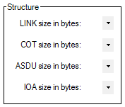
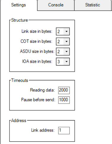
Settings
|
Structure |
||||
|
|
|
Monitor |
Master |
Slave |
|
LINK size in bytes |
LINK size in bytes |
LINK size in bytes |
LINK size in bytes |
|
|
COT size in bytes |
COT size in bytes |
COT size in bytes |
COT size in bytes |
|
|
ASDU size in bytes |
ASDU size in bytes |
ASDU size in bytes |
ASDU size in bytes |
|
|
IOA size in bytes |
IOA size in bytes |
IOA size in bytes |
IOA size in bytes |
|
|
Address |
||||
|
|
|
Monitor |
Master |
Slave |
|
Link address |
Not used |
Remote device address |
Own system address |
|
|
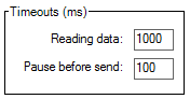
Timeouts (ms) |
||||
|
|
|
Monitor |
Master |
Slave |
|
Reading data |
Waiting data in serial port buffer |
Waiting data in serial port buffer |
Waiting data in serial port buffer |
|
|
Pause before send |
Not used |
Pause before send data |
Pause before send data |
|
|
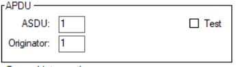
Parameters |
||||
|
|
|
Monitor |
Master |
Slave |
|
Send End of ini. |
Not used |
Not used |
Send end of initialization TI 70 (M_EI_NA_1) |
|
| Auto ack. control commands |
Not used |
Not used |
Auto acknowledge system commands (TI: 100, 103) |
|
|
Auto ack. system commands |
Not used |
Not used |
Auto acknowledge commands |
|

System
For all system functions user can set custom address:
General Interrogation
This function will send telegram Type-identification = 100 (C_IC_NA_1)
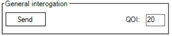
QOI - qualifier of interrogation [0...255]
- 20 - Station interrogation
- 21 - Interrogation of group 1
- 22 - Interrogation of group 2
- 23 - Interrogation of group 3
- 24 - Interrogation of group 4
- 25 - Interrogation of group 5
- 26 - Interrogation of group 6
- 27 - Interrogation of group 7
- 28 - Interrogation of group 8
- 29 - Interrogation of group 9
- 30 - Interrogation of group 10
- 31 - Interrogation of group 11
- 32 - Interrogation of group 12
- 33 - Interrogation of group 13
- 34 - Interrogation of group 14
- 35 - Interrogation of group 15
- 36 - Interrogation of group 16
Counter Interrogation
This function will send telegram Type-identification = 101 (C_CI_NA_1)
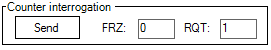
FRZ - freeze[0..3]
- 0 - Station interrogation
- 1 - Interrogation of group 1
- 2 - Interrogation of group 2
- 3 - Interrogation of group 3
RQT - request[0..63]
- 1 - Counter group 1
- 2 - Counter group 2
- 3 - Counter group 3
- 4 - Counter group 3
- 5 - General request
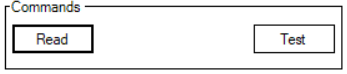
Commands
Read command will send telegram Type-identification = 102 (C_RD_NA_1)
Test command will send telegram Type-identification = 104 (C_TS_NB_1)
Clock synchronization
This function will send telegram Type-identification = 103 (C_CS_NA_1)
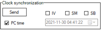
If "PC time" checkbox is checked, then the PC time will be sent. If it's not checked user can set time manually.
Time tag status bits:
- IV - invalid time
- SM - Summer/Winter
- SB - Substitute
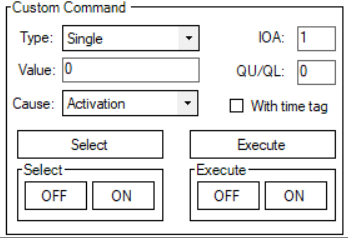
Custom Commands
This function allows user to send commands to the slave device.
Tags
This function allows user to created named points. After points created user can send it manually or set reply checkbox to automatic reply.
There are two ways of creating tags:
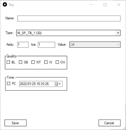
Main parameters:
- Name - user-friendly tag name
- Asdu - Identifier of the device
- Ioa - Identifier of values from the device.
- Type - the type of value.
Here is an example image of the tag window with the M_SP_TB_1 (30) type selected. Each type has different options that can be configured when sending data. For example this type depicted in the picture below can send a value Off or On and it also is time-tagged. The user in this case can either select a specific time that they have in mind or just mark the PC checkbox and The Vinci software will automatically send the current PC time. As you can see the Value box in this example is greyed out that is because this tag is created on a master simulation, and this type doesn't support writing to slave.
Setup
To setup an IEC 60870-5-101 simulation it is fairly straightforward.
1. Select IEC 60870-5-101 and the mode.

2. Select Serial Port settings according to your device specification.

3. Select settings in the settings tab according to your device and preference.
4. Press the green START button and the simulation should start. If everything was done correctly The Vinci software should establish communication with the IEC 60870-5-101 device which you can monitor in the console tab.