20.3 Example project
The best way to understand basics of 4Diac and WCC Lite collaboration is through an example project. This user manual intends to show the pieces needed to run PLC applications on WCC Lite. It is not intended to be definitive guide on how to use 4Diac IDE or how to interpret IEC 61499 standard.
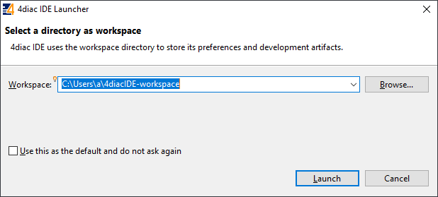
During (at least) the first start of the IDE user will be asked to select a directory for the workspace as in Figure. Workspace is used to save files needed for projects.

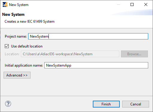
After that a user should be met by the welcome window as in Figure 20. If such window is not shown, one can create create project by selecting File->New->Project and filling in the required fields (figure 21).
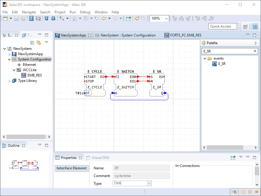
To create a simple application, simply drag and drop objects from the palette to the canvas and wire them accordingly. Event trigger and data pathways cannot be connected to one another. Displayed below is an example of a simple blinker application (figure 22).
Having less wiring by connecting several signals to same subnet as PCB designer (such as Altium Designer) as of 4Diac IDE 1.11.3 is not supported. However, if some parts are used frequently, it is highly advised to have less wiring by simply compiling several elements into a subapplication. For this, you would have to select elements to be grouped, press right key and select New Subapplication. You can later change names of such elements and its pins.
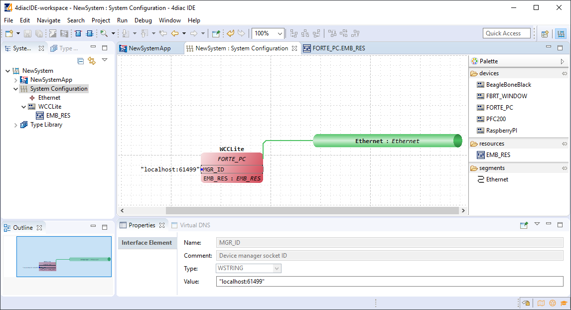
In the System Configuration section, drag and drop a FORTE_PC device, an Ethernet segment and link them (figure 23). For debugging in the local (PC) runtime, leave the address ”localhost:61499”. For testing on a WCC Lite, enter the IP address of the device, along with the port number (which by default is 61499 as well).
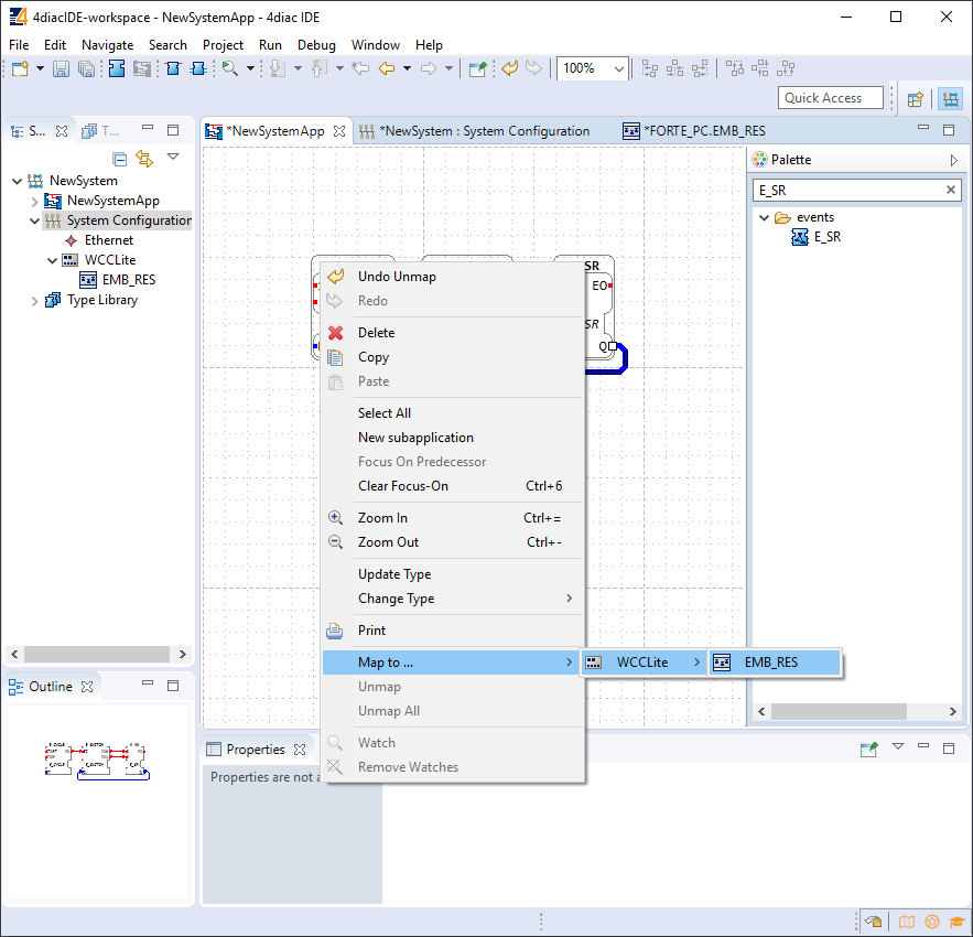
In order to deploy the application, the circuit needs to be mapped to the controller. For a non-distributed application (distributed application cases will not be discussed in this chapter), all the FBs of the application need to be selected and mapped to the configured controller as shown in figure 24.
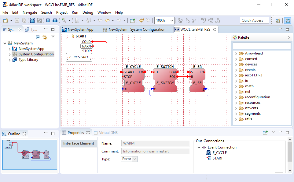
To start the application execution, an initial trigger needs to be present. For a non-distributed application, the initial event trigger needs to be wired from the START function block in the resource section as shown in figure 25.
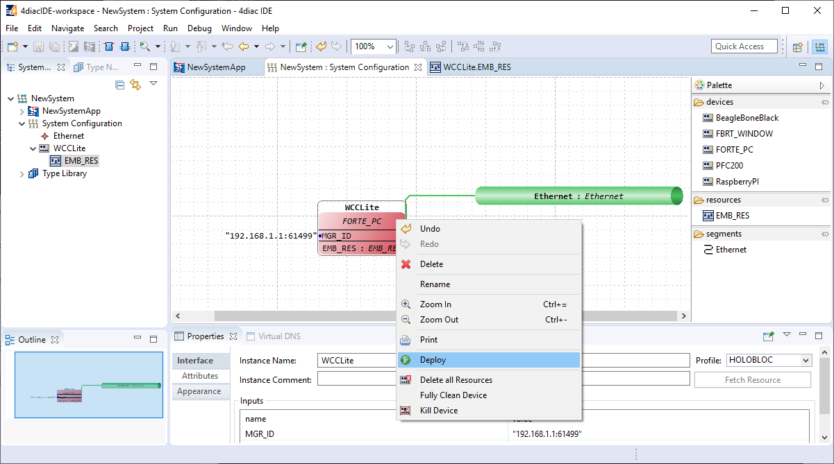
To deploy the application, go to the System Configuration tab and simply select ”Deploy” from the right-click menu of the controller device (figure 26). If a running application exist in the runtime, you may be asked whether you want to replace it. This will only overwrite the application in the memory and not the storage. If the controller is restarted, the old application will be loaded from the
non-volatile memory of the controller.