33.2 Signals Configuration
The signals sheet contains all signals linked to devices. Each signal is defined in a single row. The Signal list can be split into multiple sheets. Each sheet name may start as Signals.
Required attributes
These attributes are mandatory for every configured signal. Every Excel configuration should have specified them in the first row of the Signals sheet:
-
signal_name - Name of the signal. Used for representation only.
-
device_alias - Alias of a device defined in Devices sheet. A signal is linked to a matching device.
-
signal_alias - A unique short name for the signal. It is used for linking signals to other signals. The alias can only contain alphanumeric characters and dashes ( - and _ ). Device and signal alias combination must be unique.
Optional attributes
Optional attributes are required depending on the protocol in use and they can be used to extend protocol functionality:
-
source_device_alias - Alias of a source device defined in Devices sheet. If a user intends to use several signals and combine them via mathematical or logical function, every alias should be separated by a newline symbol (in the same cell). An operation used must also be defined in an operation column.
-
source_signal_alias - Alias of a source signal defined in Signals sheet. If a user intends to use several signals and combine them via mathematical or logical function, every alias should be separated by a newline symbol (in the same cell). An operation used must also be defined in an operation column. Each
source_signal_aliasshould be posted in the same line as its respectivesource_device_alias. Aliases can only contain alphanumeric characters and dashes ( - and _ ). Device and signal alias combination must be unique. -
enable - Flag to enable or disable signal on the system. Can contain values 0 or 1.
-
tag_type - Tag type. Simple signals are polled from the device. Virtual signals are computed
internally.
-
off_message - Message to display when a single point or double point signals are in OFF state.
-
on_message - Message to display when a single point or double point signals are in ON state.
-
units - Signal value measurements units.
-
multiply - Multiply value by this number.
- add - Add this number to a value.
- sum_signals - Define other signal values to add to the current signal. This field uses following
format: dev_alias/tag_alias. Multiple signals can be defined using commas.
-
min_value - Minimum expected value. If the result is lower than this value, the invalid flag is raised.
-
max_value - Maximum expected value. If the result is higher than this value, the overflow flag is raised.
-
absolute_threshold - Absolute threshold level.
-
integral_threshold - Integral threshold level.
-
integral_threshold_interval - Integral threshold addition interval in milliseconds.
-
threshold_units - Units used in threshold level fields (percent/real).
-
log_size - Maximum number of records for this tag to keep in storage for CloudIndustries logging.
-
suppression_values - Space-separated numeric values to be used in suppression.
-
suppression_time_ms - Suppression time in milliseconds.
-
operation - Mathematical or logical operation to be used for signals defined in source_signal_alias column. Following mathematical operations for source signal values can be used: avg (average of all values), min (lowest value), max (highest value), median (median value), and sum (all values accumulated to a single number). Logical operations, intended for unsigned integers only.
-
bit_select - selecting an individual bit of an integer number; bit numeration starts from zero.
-
math_expression - a mathematical expression for signal value to be evaluated against. Explained in detail in
Mathematical expressions document.
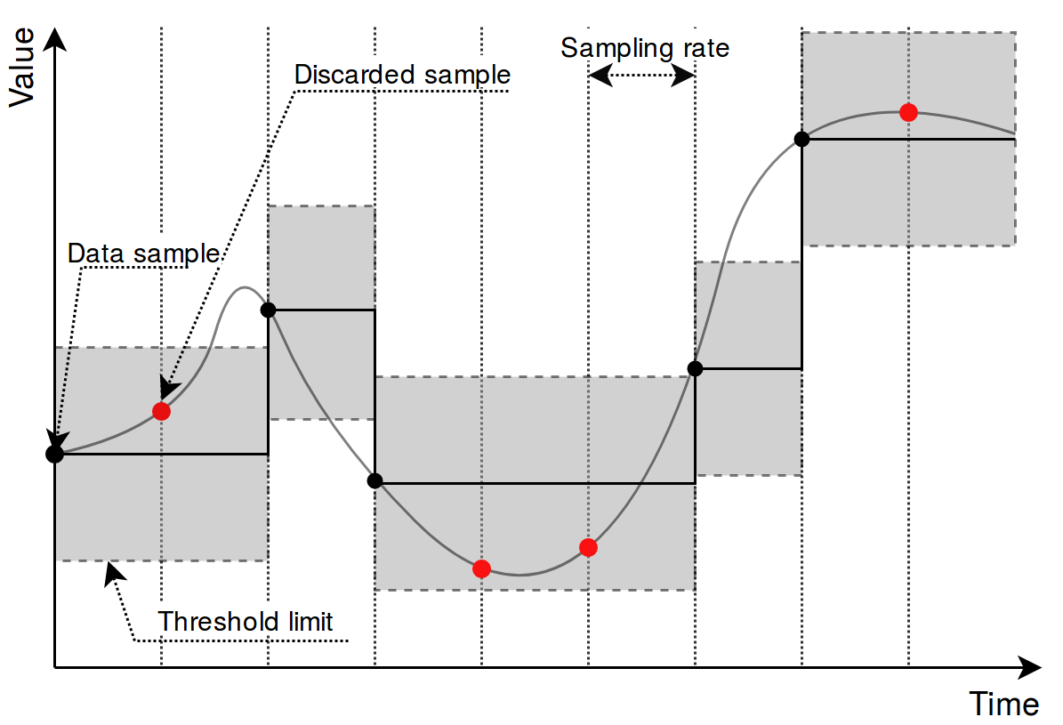
Picture. Result of using an absolute threshold:
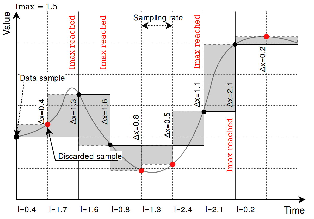
Picture. Result of using an integral threshold:
Signal recalculation operation priority
A value generated by some protocol usually has to be recalculated in one way or another. This might mean changing the value of an argument as well as adding flags needed for other protocols to correctly interpret results. As recalculation is a sequential process, some actions are done before others. The sequence of operations done to a value is as follows:
-
Edition of attributes. Attributes for further interpretation are added. This might, for example, include a flag to show that a signal resembles an answer to a command;
-
Mathematical calculations. multiply, add, bit_select, and math_expression columns are evaluated here;
-
Usage of last value. Decision if last value for a signal should be used if a new value of a signal is not a number (NaN) or contains a non-topical (NT) flag;
-
Limiting of values. If a value exceeds a lower or higher configured limit, value is approximated not be lower (or higher) than the limit. An additional invalid (IV) or overflow (OV) flag is added as frequently used in IEC-60870-5 protocols;
-
Suppresion of values. As electrical circuits can be noisy, protocols may generate multiple values in a short amount of time. What is more, some values are considered as intermediary and ideally should not be sent to SCADA unless they stay in the same state for some amount of time. suppression_values and suppression_time_ms are used to configure this functionality;
-
Threshold checking. If a new signal doesn’t cross a threshold target value, value is supressed and not used in further stages. absolute_threshold, integral_threshold, integral_threshold_interval, threshold_units columns are used to configure this functionality.
Not all of the elements in this sequence have to configured, missing operation are skipped and values are fed to a further stage of signal recalculation.
number_type field
This field is required for some protocols to determine a method to retrieve a signal value from hexadecimal form. Available values:
• FLOAT - 32-bit single precision floating point value according to IEEE 754 standard
• DOUBLE - 64-bit double precision floating point value according to IEEE 754 standard
• DIGITAL - 1-bit boolean value
• UNSIGNED8 - 8-bit unsigned integer (0 - 255)
• SIGNED8 - 8-bit signed integer (-128 - 127)
• UNSIGNED16 - 16-bit unsigned integer (0 - 65535)
• SIGNED16 - 16-bit signed integer (-32768 - 32767)
• UNSIGNED32 - 32-bit unsigned integer (0 - 4294967295)
• SIGNED32 - 32-bit signed integer (-2147483648 - 2147483647)
• UNSIGNED64 - 64-bit unsigned integer (0 - 18446744073709551615)
• SIGNED64 - 64-bit signed integer (-9223372036854775808 - 9223372036854775807)
Number conversion uses big endian byte order by default. Converted data will be invalid if byte order on connected device side is different. In such case byte swap operations can be used. Adding swap prefixes to number type will set different a byte order while converting values. Following swap operations are available:
-
SW8 - Swap every pair of bytes (8 bits) (e.g., 0xAABBCCDD is translated to 0xBBAADDCC);
-
SW16 - Swap every pair of words (16 bits) (e.g., 0xAABBCCDD is translated to 0xCCDDAABB);
-
SW32 - Swap every pair of two words (32 bits) (e.g., 0x1122334455667788 is translated to 0x5566778811223344);
Table. Example of using different swapping functions:
| Address | 0 | 1 | 2 | 3 | 4 | 5 | 6 | 7 |
| Original number | Byte 0 | Byte 1 | Byte 2 | Byte 3 | Byte 4 | Byte 5 | Byte 6 | Byte 7 |
| SW8 | Byte 1 | Byte 0 | Byte 3 | Byte 2 | Byte 5 | Byte 4 | Byte 7 | Byte 6 |
| SW16 | Byte 4 | Byte 5 | Byte 6 | Byte 7 | Byte 1 | Byte 6 | Byte 4 | Byte 5 |
| SW32 | Byte 4 | Byte 5 | Byte 6 | Byte 7 | Byte 0 | Byte 1 | Byte 2 | Byte 3 |
| SW8.SW16 | Byte 3 | Byte 2 | Byte 1 | Byte 0 | Byte 7 | Byte 6 | Byte 5 | Byte 4 |
| SW8.SW32 | Byte 4 | Byte 4 | Byte 7 | Byte 6 | Byte 1 | Byte 0 | Byte 3 | Byte 2 |
| SW8.SW16.SW32 | Byte 7 | Byte 6 | Byte 5 | Byte 4 | Byte 3 | Byte 2 | Byte 1 |
Byte 0 |
Where Byte x, means bit x position in byte.
Add a dot separated prefix to number format to use byte swapping. Multiple swap operations can be used simultaneously. For example, use SW8.SW16.SIGNED32 to correctly parse a 32-bit signed integer in a little endian format. Table 35 shows in detail how bytes, words or double words can be swapped and how swapping functions can be combined to make different swapping patterns. Table shows how byte swap is done for 64-bit (8-byte) numbers. It doesn’t matter if it is an unsigned/signed integer or double, byte swapping is considered a bit-level operation. If a number is shorter than 64 bits, the same logic applies, the only difference is unavailability of some swapping operations (SW32 for 32-bit and smaller numbers). Using such unavailable operation might lead to an undefined behaviour.
Linking signals
Signals can be linked together to achieve data transfer between several protocols. If a signal source is defined, all output from that source will be routed to the input of target signal. This way events polled from a modbus device (e.g., Modbus, IEC 60870-5, etc.) can be delivered to external station over a different protocol. A signal source is required if a signal is created on a slave protocol configuration to link events between protocols.
Example 1:
To read a coil state from a Modbus device and transfer it to IEC 60870-5-104 station, following steps may be taken:
-
Create a Modbus master configuration in Devices sheet.
-
Create a IEC 60870-5-104 slave configuration in Devices sheet.
-
Create a signal on master device to read coil status (function 1).
-
Create a signal on slave device with single point type (data_type = 1).
-
Set source_device_alias and source_signal_alias fields on slave device signal to match device_alias and ignal_alias on master device’s coil signal.
Example 2
To write a coil state to a Modbus device on a command from IEC 60870-5-104 station, following steps may be taken:
-
Follow steps 1-3 from example 1.
-
Create a signal on slave device with single command type (data_type = 45).
-
Set source_device_alias and source_signal_alias fields on master configuration coil signal to match device_alias and signal_alias on slave device’s command signal. Coil will be written to a value received by a command.
-
Set source_device_alias and source_signal_alias fields on command signal to match device_alias and signal_alias on master device’s coil signal. A command termination signal will be reported to the station on coil write result.
For additional information regarding the configuration of IEC 60870-5-101/103/104 protocols, please refer to ”IEC 60780-5-101/103/104 PID interoperability for WCC Lite devices”, accordingly.
Introduction
Signal value might require some recalculation or signal update prior to being sent. Understandably, existing columns in Excel configuration like multiply, add, bit_select might not be flexible enough. To overcome these limitations, symbolic mathematical expressions can be configured to do calculations automatically on every update of a signal.
It should be noted that filling mathematical expression disables other mathematical scalar operations for a single value such as multiply, add or bit_select. Other functions (primarily between several signals) are still available such as operation.
Feature list:
- Optimized for speed
- High parsing performance
- if-then-else operator with lazy evaluation
- Default implementaion with many features
-
25 predefined functions
-
18 predefined operators
-
-
Unit support
-
Use postfix operators as unit multipliers (3m -> 0.003)
-
Mathematical functions
Table. Supported mathematical functions:
| Name | Argument count | Explanation |
| sin | 1 |
sine function (rad) |
| cos | 1 |
cosine function (rad) |
| tan | 1 |
tangent function (rad) |
| asin | 1 |
arcus sine function (rad) |
| acos | 1 |
arcus cosine function (rad) |
| atan | 1 |
arcus tangens function (rad) |
|
sinh |
1 |
hyperbolic sine function |
| cosh | 1 |
hyperbolic cosine |
| tanh | 1 |
hyperbolic tangens function |
| asinh | 1 |
hyperbolic arcus sine function |
| acosh | 1 |
hyperbolic arcus tangens function |
| atanh | 1 |
hyperbolic arcur tangens function |
| log2 | 1 |
logarithm to the base 2 |
| log10 | 1 |
logarithm to the base 10 |
| log | 1 |
logarithm to base e (2.71828...) |
| ln | 1 |
logarithm to base e (2.71828...) |
| exp | 1 |
e raised to the power of x |
| sqrt | 1 |
square root of a value |
| sign | 1 |
sign function -1 if x<0; 1 if x>0 |
| rint | 1 |
round to nearest integer |
| abs | 1 |
absolute value |
| min | variable |
min of all arguments |
| max | variable |
max of all arguments |
| sum | variable |
sum of all arguments |
| avg | variable |
mean value of all arguments |
It should be noted that trigonometric functions (excluding hiperbolic functions) only support arguments in radians. This means that arguments for this function have to be recalculated if angle is defined in degress.
Value recalculation is only triggered on signal change of the preconfigured signal. That means that using other signals (via TagValue() call) does not trigger value update.
Some mathematical expression cannot be mathematically evaluated in some conditions, for example, square root cannot be found for negative numbers. As complex numbers are not supported, result is then equal to Not a Number (NaN). These results are marked with an invalid (IV) flag.
Binary operations
Table. Supported binary operators:
| Operator | Description | Priority |
|
= |
assignment |
-1 |
|
» |
right shift |
0 |
|
« |
left shift |
0 |
|
& |
bitwise and |
0 |
|
| |
bitwise or |
0 |
|
&& |
logical and |
1 |
|
|| |
logical or |
2 |
|
<= |
less or equal |
4 |
|
>= |
greater or equal |
4 |
|
!= |
not equal |
4 |
|
== |
equal |
4 |
| > |
greater than |
4 |
| < |
less than |
4 |
| + |
addition |
5 |
| - |
subtraction |
5 |
| * |
multiplication |
6 |
| / |
division |
6 |
|
^ |
raise x to the power of y |
7 |
Ternary operators can be used. This expression can be compared to the operator supported by C/C++ language (Table 39). Condition is written before a question (?) sign. If condition is true, result after question sign is selected. If condition is false, result after colon (:) is selected.
Ternary operations
Table. Supported ternary operators
| Operator | Description | Remarks |
|
?: |
if then else operator |
C++ style syntax |
Examples
User can construct his own equation by using the aforementioned operators and functions. These examples can be seen in Table bellow.
Table. Example expressions
|
Expression |
Description |
|
value * 0.0001 |
Multiply the tag by a constant. |
|
value + TagValue(”tag/dev_alias/sig_alias/out”) |
Add value of tag/dev_alias/sig_alias/out to the current tag. |
|
sin(value) |
Return a predefined sine function value of the tag. |
|
(value>5)? 1: 0 |
If value is greater than 5, result should be equal to 1, otherwise - equal to 0 |
Variable called value is generated or updated on every signal change and represent the signals being configured. If another value from tag list is intended to be used, one should use TagValue() function to retrieve its last value.
The inner argument of TagValue() function has to described in a Redis topic structure of WCC Lite. That means that it has to be constructed in a certain way. Quotes should be used to feed the topic name value, otherwise expression evaluation will fail.
Every Redis topic name is constructed as tag/[device_alias]/[signal_alias]/[direction]. Prefix tag/ is always used before the rest of argument. device_alias and signal_alias represent columns in Excel configuration. direction can have one of four possible values - rout, out, in, rin; all of which depend on the direction data is sent or acquired device-wise. For example, out keyword marks data sent out of WCC Lite device, whereas in direction represents data that WCC Lite is waiting to receive, for example, commands. Additional r before either direction means that data is raw, it was is presented the way it was read by an individual protocol.
Extra functions
Several functions are defined make tag operations possible:
TagValue(key)- returns last known value of tag identified by redis key;TagFlag(key)- returns 1 if tag flag exists. Name format is: ”key flag”. For example to check if tag is notopical, name would be ”tag/19xxxxxxx/x/x nt”;TagAttribute(key)- similar to TagFlag, but returns a numeric value of a tag attribute;TagTime(key)- returns unix timestamp in milliseconds of a last know tag value.