Testing IOMod 8DI8DO IEC-103
Initial Setup
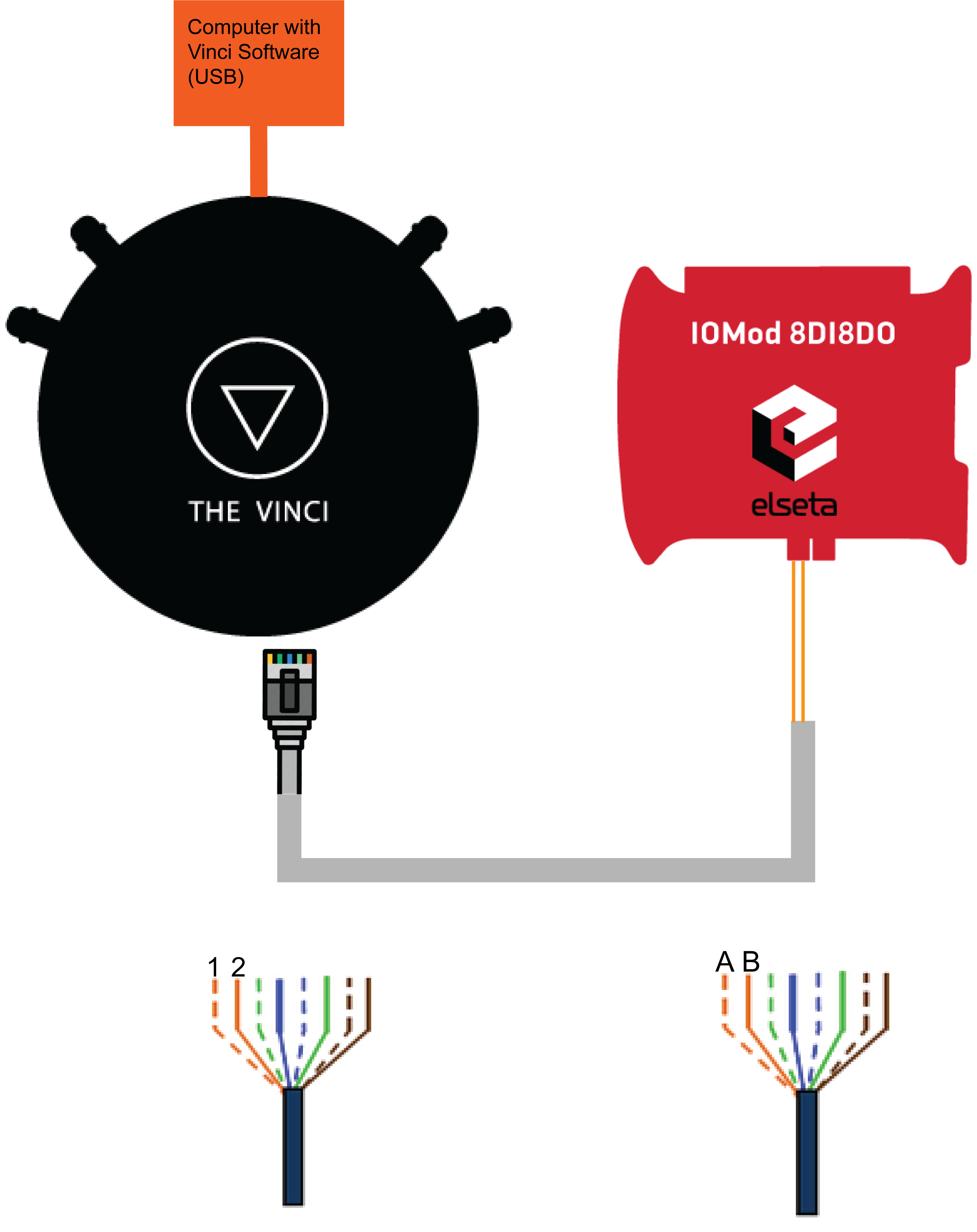
The first thing to do when setting up is to connect the IOMod to the computer using The Vinci Expert to convert from RS485 to USB. You need to connect it like in the diagram depicted below.
- Connect The Vinci Device to the computer using a micro USB cable.
- Using an ethernet cable connect one end to the Vinci, and the other two wires to IOMod A and B pins.
- If the wire is connected using RJ-45 the A wire will be the orange striped wire and the B wire will be the single color orange wire.
- Lastly, connect the 12-24 VDC power input.

To test IOmod with default settings, the user connects the device through RS485 to IEC 60870-5-103 master. For example, using “The Vinci Expert” as a serial interface converter and adapter to PC with “The Vinci” software. When opening “The Vinci” software, choose IEC 60870-5-103 – Master mode. Initial settings – 9600 baud rate; 8 data, no parity, 1 stop bit. Press Start, send Time synchronization, General interrogation, and go to the “Statistic” tab:
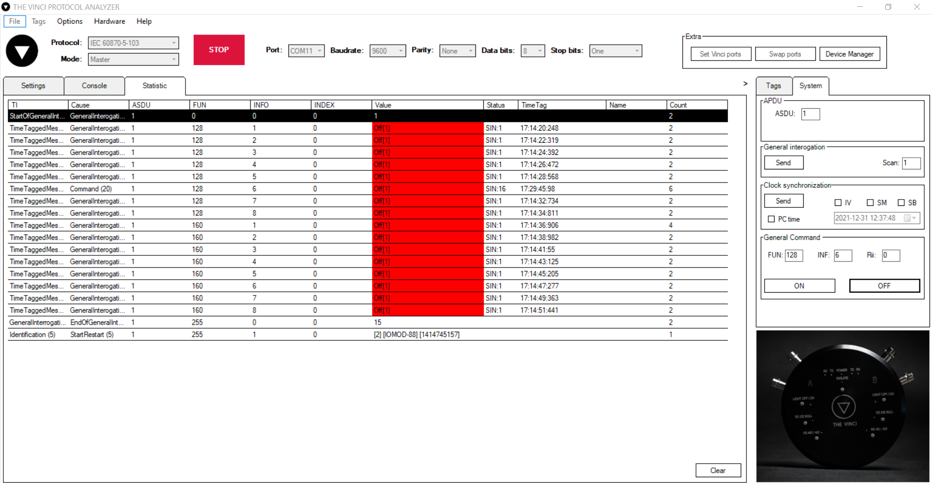
Fig. 1. Testing IOMOD device with “THE VINCI” software
As seen in Figure 1, Outputs and inputs are shown with info numbers 1-8, and function types are 128 and 160 respectively.
General Interrogation, Time Synchronization, and General Command options can be found on the right side of the program, in the “System” tab.
Output commands are controlled by the “General command” window on the right side of the program, in the “System” tab, with Output address (Function type) 128, and output number (Info number).
Figure 2 shows the 6th output command sent and the “CMD ACK” response received.
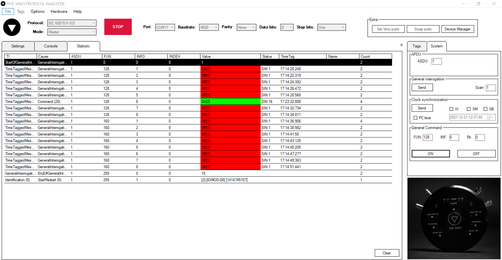
Fig. 2 Replies from IOmod device after a command has been sent through “THE VINCI” software