IEC 101 Slave Simulator Tutorial
Initial Setup
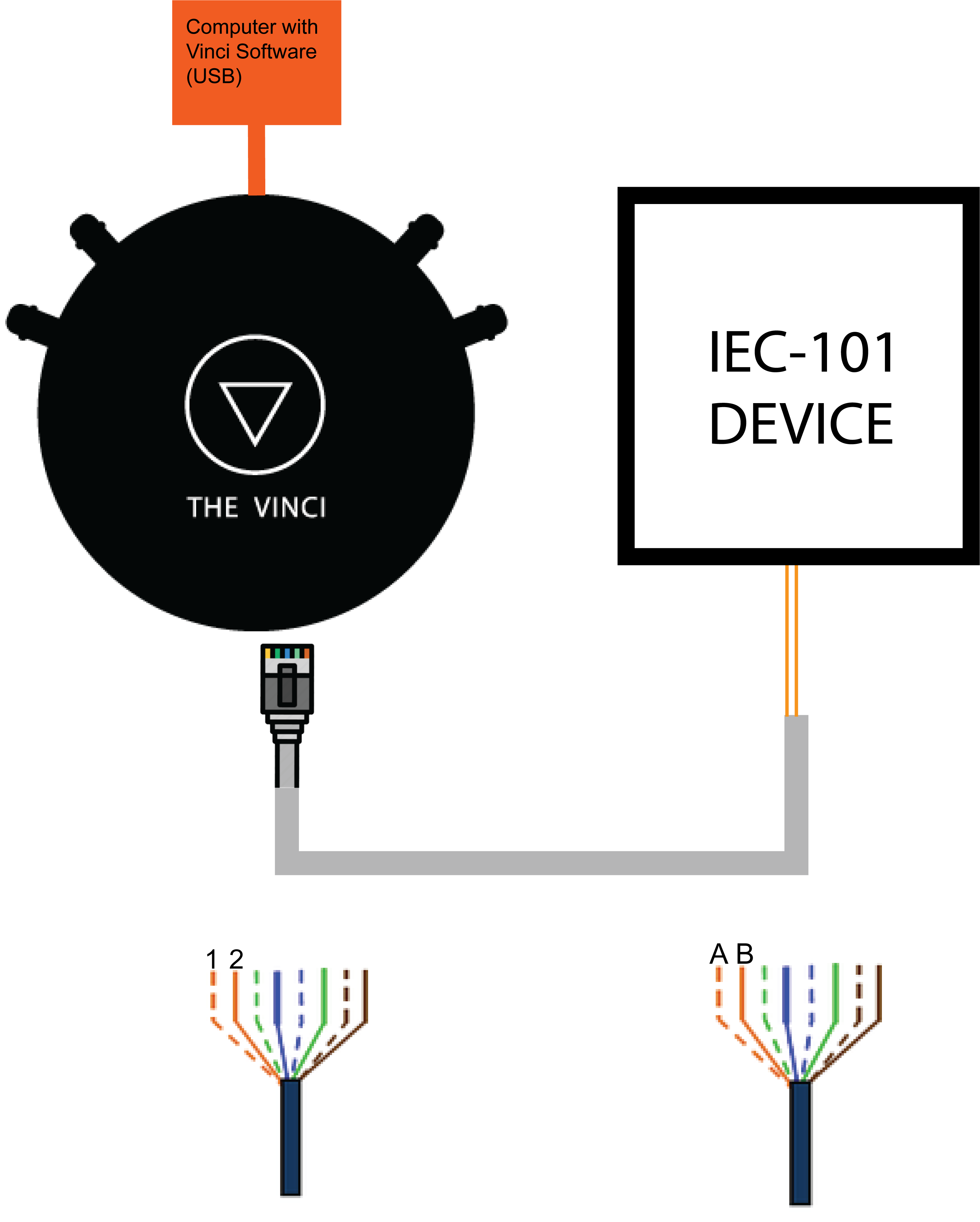
The first thing to do when setting up is to connect the IOMod to the computer using The Vinci Expert to convert from RS485 to USB. You need to connect it like in the diagram depicted below.
- Connect The Vinci Device to the computer using a micro USB cable.
- Using an ethernet cable or connect one end to the Vinci, and the other two wires to IEC101 Device A and B pins.
- If the wire is connected using RJ-45 the A wire will be the orange striped wire and the B wire will be the single color orange wire.
Standard settings in the Vinci software are for an RJ-45 cable, but it is configurable using the Hardware tab.
Selecting protocol and mode
Fig. 1. Selecting protocol and mode
After the ethernet cable has been connected it's time to open The Vinci Software and start configuring the simulated device parameters. Since The Vinci Expert will simulate the Slave (Server) when the software is started just select the IEC 60870-5-101 protocol and select Slave mode.
Selecting the Serial parameters
Fig. 2. Selecting the Serial parameters
The next step is to choose the correct serial port for your device and then set up serial communication parameters like baudrate, parity, databits, and stopbits in accordance with your device.
Selecting the protocol parameters
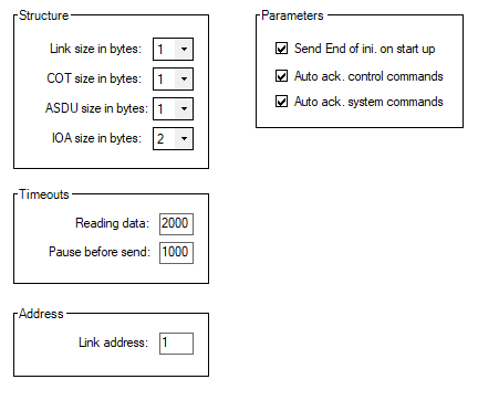
Fig. 3. Selecting the protocol parameters
Go to the settings tab when you have serial communication parameters configured. Now it's time to configure your device according to your Device settings. The defaults that are here are usually the defaults in most cases, but make sure to double-check.
Establishing a connection with the device
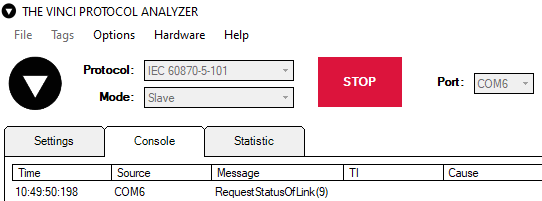
Fig. 4. Establishing a connection with the device.
Pressing the green "START" button should establish serial communication with the device. After the device responds with link status tags can be sent. Tags can be found on the right side of the Vinci software in the system tab.
Simulating an IOMod
This example will show how to simulate an IOMod using Vinci Protocol Analyzer. In the example below 4RTD IOMod is simulated.
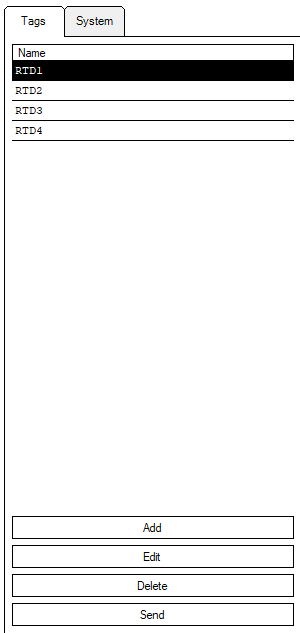
Firstly, to simulate an IOMod tags should be created by clicking "Add" button. Tags are simulating signals that would be overwise sent by a real IOMod (4RTD in this case).
In order to create a tag some values from Excel configuration will be required.
 Fig. 6. Signals sheet of 4RTD IOMod.
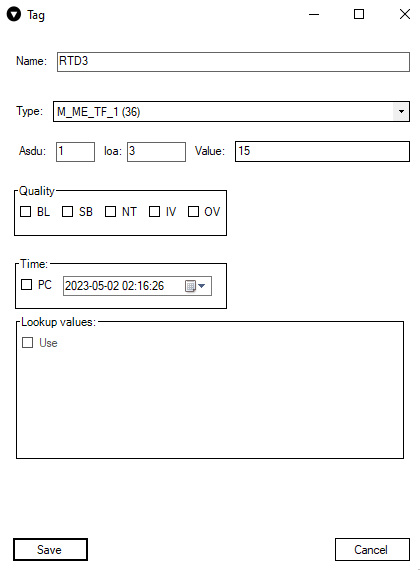
In the picture below a tag creation window is shown. It opens after clicking "Add" button. To create a tag the Name has to be specified. After that the Type has to be specified. The type can be found in "data_type" column of Excel configuration. After that "Ioa" has to be specified. Its value for each tag can be found in "info_address" column. Lastly, a random value can be specified in "Value" box. Finally the tag can be saved by clicking "Save" button.
The created tags can be seen in WCC Lite Imported Signals section in browser.
 Fig. 8. Imported Signals tab in browser.
They can also be seen in Statistics section of Vinci application.
Fig. 9. Previously created tags in Statistics section of Vinci.
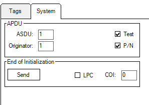
The state of the signals can be changed in System section of Vinci application by ticking Test or/and P/N options.
Fig. 10. Selecting Test and P/N options.
The change of signal states will be seen in WCC Lite Imported Signals section in browser.
Fig. 11. Changed State of signals after selecting Test and P/N options.

