IOMod 4RTD User Manual
1. Introduction
IOMod 4RTD is a standalone temperature sensor device. Designed to measure temperature over a wide range with high accuracy and repeatability even during frequent heating and cooling cycles. 4RTD is equipped with 4 temperature channels to enable temperature reading with default configuration. The measured values are transmitted to the host system via communication protocol Modbus RTU, IEC 60870-5-101 or IEC 60870-5-103.
1.1 Features
- Firmware upgrade over USB, RS485;
- Configurable using the IOMod Utility application for user-friendly setup;
- RS485 interface with a switchable terminating resistor;
- Compact case with a removable transparent front panel;
- DIN rail mounting for seamless integration into industrial systems;
- Temperature sensing with ±0.5 °C accuracy in all operating conditions;
- 2.5 kV (RMS) isolated RTD inputs;
- Temperature sensing ranges from -200 °C up to 800 °C when using platinum RTD sensors.
1.2 Block Diagram
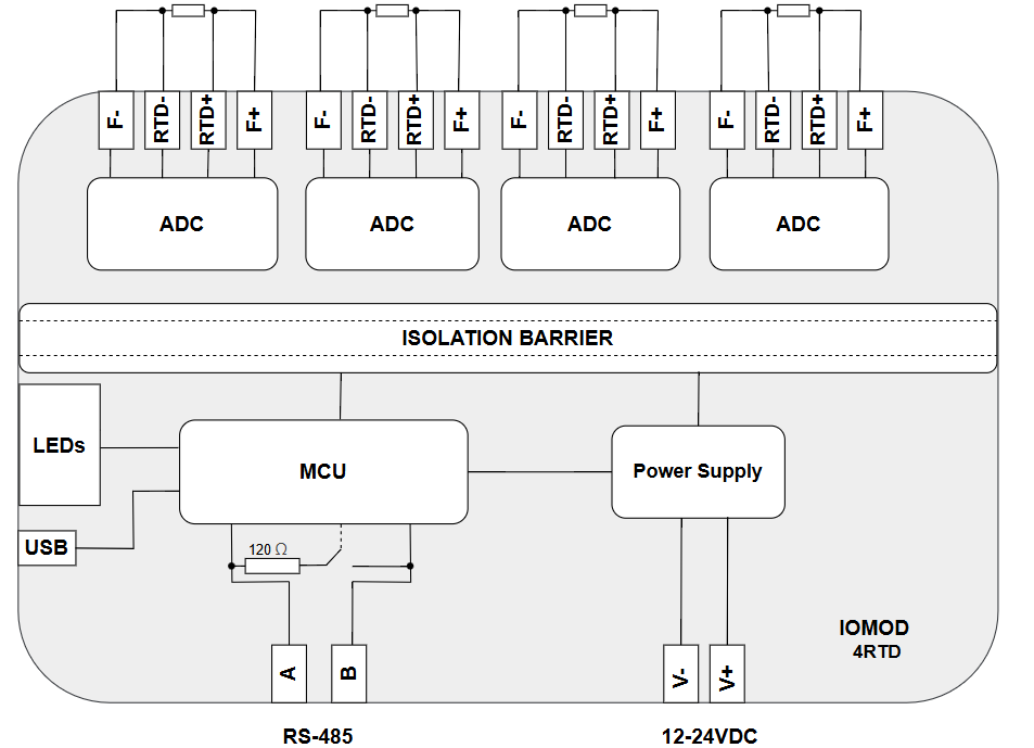
Fig. 1.2.1 IOMod 4RTD internal structure and block diagram
2. Hardware data
2.1 Mechanical drawings
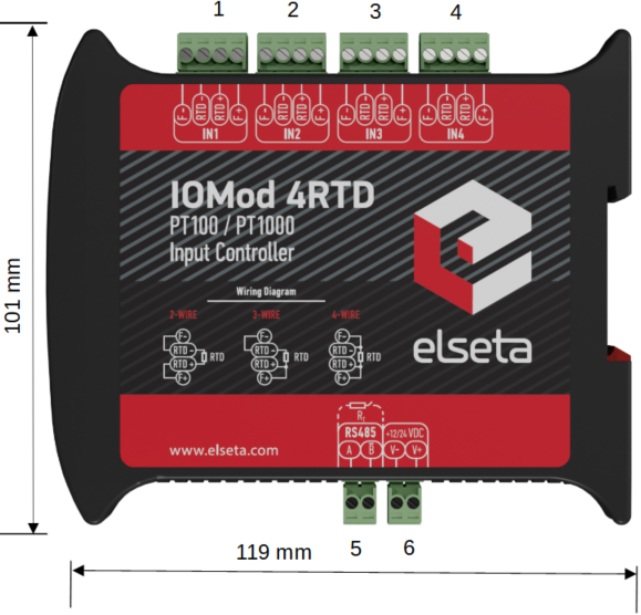
Fig. 2.1.1 IOMod 4RTD side view with dimensions and terminals description.
1–4 sensor inputs, 5 – RS485 interface, 6 – power supply input
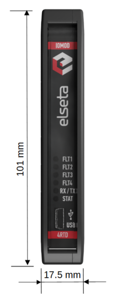
Fig. 2.1.2 IOMod 4RTD front view with dimensions
2.2 Terminal connections
IOMod 4RTD has 20 terminals, which are depicted below:

Fig. 2.2.1 IOMod 4RTD terminal diagram
The description of each terminal can be found in the table below:
Table 2.2.1 Terminal Specifications
|
Terminal number |
Terminal name |
Description |
|---|---|---|
|
1, 5, 9, 13 |
F - (IN1–IN4) | The negative excitation terminal, completing the circuit for the supplied current |
|
2, 6, 10, 14 |
RTD - (IN1–IN4) | This terminal is connected to the negative terminal of the RTD element, providing a reference voltage for accurate resistance measurement |
|
3, 7, 11, 15 |
RTD + (IN1–IN4) | This terminal is connected to the positive terminal of the RTD element and measures the voltage drop across it |
|
4, 8, 12, 16 |
F + (IN1–IN4) | This is the positive excitation or supply current terminal that provides a constant current source to the RTD element |
|
17 |
A |
RS485 input |
|
18 |
B̄ | |
|
19 |
V- |
Power source input |
|
20 |
V+ |
2.3 Status indication
IOMod 4RTD has six LEDs (Fig 2.3.1), which indicate the temperature related faults, communication and power statuses. The first 4 upper LED's (FLT1–FLT4) can identify whether the temparature related faults have occurred in any of the four input channels. STAT LED indicates if a proper power connection is made. This LED is always on if the device has a power connection. Blue light means the device is only powered via USB, green light indicates the main power source is connected and red light means at least one of the faults activated. They occur when something is wrong with either the power connection or RTD channels. RX/TX status LED indicates if RS485 transmission is happening at the moment.
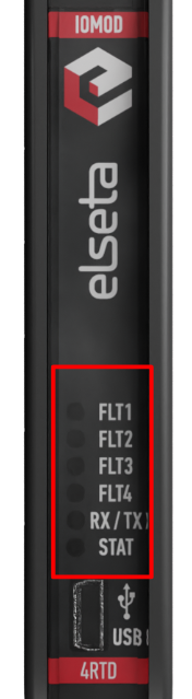
Fig. 2.3.1 IOMod 4RTD LEDs physical location
The description of each IOMod 4RTD LED can be found in the table below:
Table 2.3.1 Description of LEDs.
|
Name |
LED color |
Description |
|
FLT1–FLT4 |
⚪ (off) | Normal operation |
| 🔴 (red) | Input fault or faults occurred during the operation of the device | |
|
RX/TX |
🟢 (green) |
A blinking green light indicates active communication via the RS485 interface |
|
STAT |
🟢 (green) |
The power source is connected to the power supply input |
|
🔵 (blue) |
IOMod 4RTD is connected to an external device via a USB mini cable |
|
|
🔴 (red) |
At least one fault is active |
3. Technical information
Table 3.1 Technical specifications.
| System | |
| Dimensions | 17.5 (H) x 101 (W) x 119 (L), mm |
| Case | IP20, blend PC/ABS self-extinguishing, black |
| Working environment | Indoor |
| Operating temperature | -40°C ... +80°C |
| Recommended operating conditions | 5°C–60°C and 20%–80% RH |
| Configuration | USB, RS485 |
| Firmware upgrade | USB, RS485 |
| Electrical characteristics | |
| Termination resistor | Selectable, 120 Ω |
| Power | |
| Power Supply | 9–33 VDC |
| Current consumption | 40 mA @ 12 VDC, 20 mA @ 24 VDC |
4. Mounting and installation
4.1 RTD sensor connection
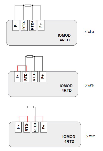
Fig. 4.1.1 3 types of RTD sensor connections. The red wire is shorted on the terminal plug
IOMod 4RTD accepts 2-wire, 3-wire or 4-wire connection types of RTD sensors (PT100, PT1000). Firstly, select a sensor type (PT100 or PT1000) using a IOMod Utility. Secondly, use the following instructions depending on the number of wires of a selected RTD sensor.
- 2-wire RTD sensor: connect wire to RTD+ and RTD- terminals. The terminals RTD+ and F+, RTD- and F- must be short circuited (Fig. 4.1.1).
- 3-wire RTD sensor: connect one wire to RTD+, a second wire (compensating lead wire) to F+ and wire to RTD-. The terminals RTD- and F- must be short circuited (Fig. 4.1.1).
- 4-wire RTD sensor: connect wires to RTD+ and F+ terminals and wires to RTD- and F- terminals. There is no need to short circuit any terminal in this scenario. (Fig. 4.1.1).
4.2 Power Supply
IOMod 4RTD can be powered through the main power connector by a +9–33 VDC power source or USB. Apply +9–33 VDC to V+ and 0 V to V-. The device has a built-in reverse voltage polarity, overcurrent and overvoltage protection.

Fig. 4.2.1 Power supply inputs physical location
4.3 USB Connection
IOMod 4RTD device has a USB-mini connection port. Its primary function is establishing a physical connection between the IOMod and a PC. By selecting the USB interface and correct communication port in IOMod Utility (Fig. 4.4.1) a user can connect to the IOMod to control its parameters and monitor its measured data and the status of fault detection functions. Also, this connection can be used to power the module.
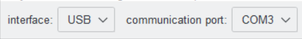
Fig. 4.3.1 IOMod Utility interface and communication port parameters
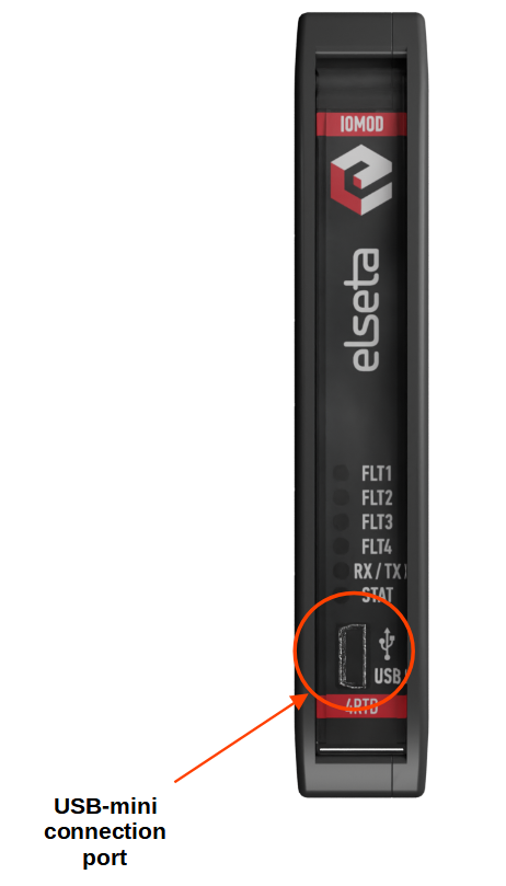
Fig. 4.3.2 IOMod 4RTD USB connection port physical location
5. Parametrization
In this section, the IOMod 4RTD settings configuration is described. IOMod 4RTD configuration is performed via IOMOD Utility (the manual can be accessed here). All IOMod-related settings can be found in the "Iomod settings" tab (Fig. 5.1).

Fig. 5.1 IOMod settings tab
5.1 IOMod Settings
To configure IOMod 4RTD general settings open the "Iomod settings" tab in IOMod Utility (Fig. 5.1.1).
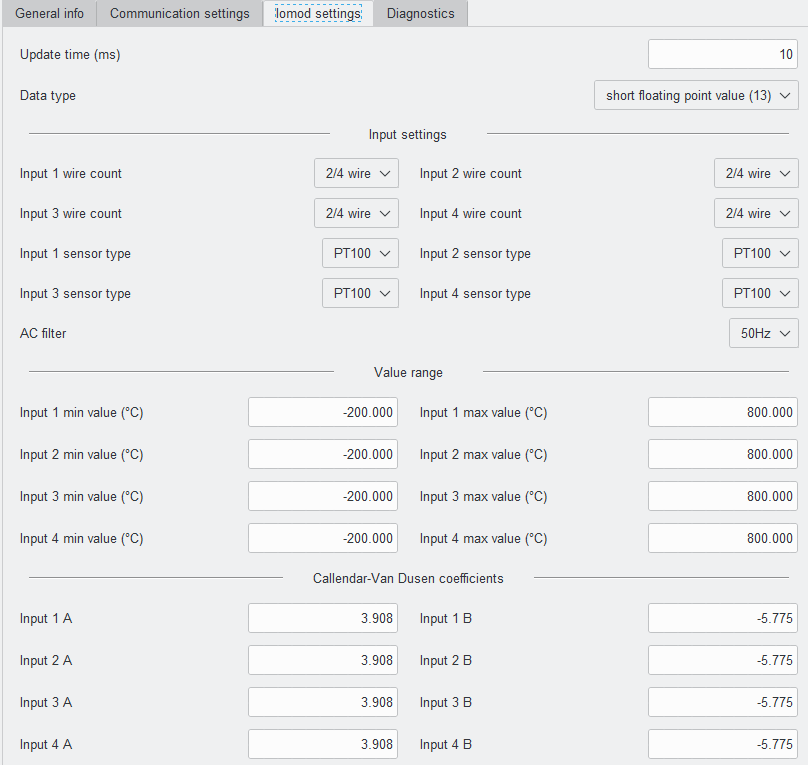
Fig. 5.1.1 IOMod Utility with IOMod 4RTD Iomod settings window opened
To configure IOMod 4RTD using IOMod Utility, first connect to a device or create a template as explained in the IOMod Utility documentation. Parameters for IOMod 4RTD can be configured on the "Iomod settings" tab. IOMod with default settings is configured as a Modbus slave device. The Iomod settings' available values and ranges can be seen in the table below (Table 5.1.1).
Table 5.1.1 IOMod 4RTD parameter ranges and default values
| Parameter | Range | Default value |
| Update time (ms)* | 10-60000 | 10 |
| Data type** | scaled value (11), short floating point value (13) | short floating point value (13) |
| Input [ ] wire count | 3 wire, 2/4 wire | 2/4 wire |
| Input [ ] sensor type | PT100, PT1000 | PT100 |
| AC filter | 50Hz, 60 Hz | 50 Hz |
| Input [ ] min value (˚C) | -200 – 800 | -200.00 |
| Input [ ] max value (˚C) | -200 – 800 | 800.00 |
| Input [ ] A | 3.908 – 3.985 | 3.908 |
| Input [ ] B | (-5.775) – (-5.850) | -5.775 |
* The parameters are defined only for IEC 60870-5-103 and IEC 60870-5-101 communication protocols.
** The parameters are defined only for the IEC 60870-5-101 communication protocol.
The update time (ms) parameter is only available for protocols IEC101 and IEC103. This parameter specifies the frequency of data sent to the buffer, which is later can be read by a master station. The Data type parameter can be changed for the IEC101 protocol. The default data type is a short floating point value (type 13), but the scaled value (type 11) can be selected as well.
For each input, the user can select either 3 or 2/4 wire count, PT100 or PT1000 sensor type and AC filter frequency – 50 or 60 Hz. These settings should be configured according to the sensor parameters.
Value range can be set without any limitations. However, it is important to know that if the measured value is lower or higher than the set, data will be returned with an overflow flag. Configuring a reasonable value range for the measured temperature range is recommended.
The Callendar–Van Dusen equation is an equation that describes the relationship between resistance (R) and temperature (T) of platinum resistance thermometers (PT). The Callendar–Van Dusen equation is expressed below:
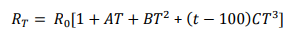
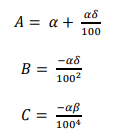
RT is resistance at a certain temperature, R0 is resistance at 0˚C and T is the temperature in ˚C. A, B and C are known as the Callendar-Van Dusen constants, defined by the following equations:
Alpha, beta and delta are constants that are found with the following equations:
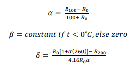
Knowing that the user can adjust the A and B coefficient values for each IOMod 4RTD input. However, default values are set according to the European Industrial Standard (Standard DIN 43760, IEC 751).
5.2 Diagnostics
The Utility diagnostics windows allow users to connect to IOMod directly and observe the values in real time. The 4RTD diagnostics window shows values of inputs in Celsius and faults. If a certain fault appears, the Diagnostics window indicates it with a blue square next to a fault type.
To turn on real-time monitoring of both Diagnostics sections, the "Connect" button to the left of the "Offline" word designation needs to be pressed. After pressing the "Connect" button the word designation of Diagnostics mode changes to "Online", the black circle starts blinking and the button name changes to "Disconnect" (Fig. 5.2.1). When a fault is detected the checkboxes are going to be checked.
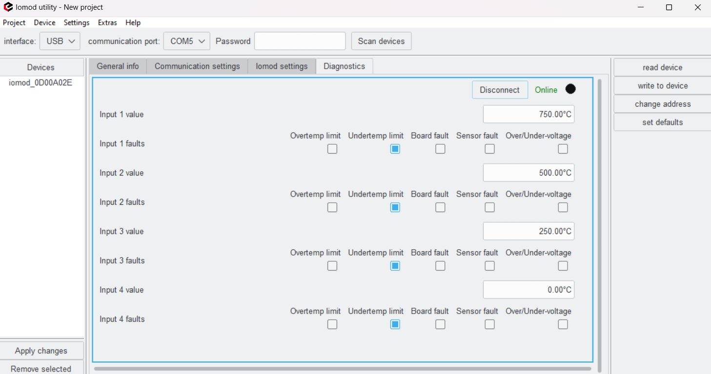
Fig. 5.2.1 IOMod Utility Diagnostics tab in online mode
6. Communication protocols
IOMod 4RTD uses Modbus (RTU), IEC-60870-103 or IEC-60870-101 protocols over Ser2Net or RS485 connection, which can be used for cable lengths up to 1500 meters and connect up to 30 devices on one line. Default Modbus, IEC-60870-103 and IEC-60870-101 settings are: 19200 bauds/s baudrate, 8E1, Slave (Link) address - 1.
Table 6 Default communication parameters
|
Protocol |
Baudrate |
Parity |
Stop bits |
Wait byte count |
Slave address |
Link address size |
ASDU size |
COT size |
IOA size |
Input function |
Output command function |
Output status function |
|---|---|---|---|---|---|---|---|---|---|---|---|---|
|
Modbus |
19200 | Even | 1 | 8 | 1 | |||||||
|
IEC 101 |
19200 | Even | 1 | 8 | 1 | 1 | 1 | 1 | 2 | |||
|
IEC 103 |
19200 | Even | 1 | 8 | 1 | 253 | 254 | 254 | ||||
*Default IOMod 4RTD communication protocol is Modbus
6.1 Modbus RTU Operational Information
To read temperatures from the RTD sensors with Modbus protocol, send the function code 4 request (Read Input Registers) to read addresses from 0 to 7. Each temperature measurand is saved as 32 bit float value and occupies two consecutive registers. Odd numbers represent the least significant words, even numbers represent the most significant words. For example, to read the temperature measured by the first RTD, read registers 0 and 1, where register 0 is the least significant word. Two words read by Modbus represent a float type (IEEE-754 compatible) number. The Modbus RTU function code 4 may be used to read current temperature values and faults.
Fault register values are read as 16-bit input registers on addresses 10 to 14. The meanings of individual bits are explained below in the subsection Fault registers (Table 6.1.2).
Table 6.1.1 IOMod 4RTD Modbus input registers
| Address (Dec) | Description | Data Type | Access |
|
0-1 |
Input 1 value |
Float |
R |
|
2-3 |
Input 2 value |
Float |
R |
|
4-5 |
Input 3 value |
Float |
R |
|
6-7 |
Input 4 value |
Float |
R |
|
10 |
Input 1 fault |
UINT16 |
R |
|
11 |
Input 2 fault |
UINT16 |
R |
|
12 |
Input 3 fault |
UINT16 |
R |
|
13 |
Input 4 fault |
UINT16 |
R |
Fault registers (Modbus addresses 10-13) are read-only. They represent faults that occurred during the operation of the device. Descriptions of possible fault values are provided in the table below (6.1.2). If everything is functioning correctly, these registers will contain a value of 0. If there is an issue, an appropriate value will be indicated.
Table 6.1.2 Fault bit mask
| Bit position | Description |
|
0 |
Reserved (default: 0) |
|
1 |
Reserved (default: 0) |
|
2 |
RTD Overvoltage/Undervoltage – The measured voltage across the RTD is too high or too low, possibly indicating a wiring issue or sensor failure |
|
3 |
RTD FORCE Open – The force lead (excitation current path) is open; the RTD may be disconnected |
|
4 |
Reserved (default: 0) |
|
5 |
RTD REFIN- > 0.85 x VBIAS – The negative reference voltage (REFIN-) is too high compared to the bias voltage, which could indicate a configuration or hardware issue |
|
6 |
RTD Code Low Threshold – The digital output code from the RTD is lower than expected, possibly indicating a sensor or wiring issue |
|
7 |
RTD Code High Threshold – The digital output code from the RTD is higher than expected, possibly indicating overheating or fault |
|
8 |
Reserved (default: 0) |
|
9 |
Reserved (default: 0) |
|
10 |
Reserved (default: 0) |
|
11 |
Reserved (default: 0) |
|
12 |
Reserved (default: 0) |
|
13 |
Reserved (default: 0) |
|
14 |
RTD Temperature Lower Threshold – The measured temperature is below the configured lower threshold |
|
15 |
RTD Temperature Upper Threshold – The measured temperature exceeds the configured upper threshold |
6.2 IEC 60870-5-101 Operational Information
To read temperature using the IEC-60870-101 protocol, the user can use the device with default settings without configuring it. The data is sent via data type 13 (measured value, short floating point value). The information object addresses (IOA) are from 1 to 4. These values are represented as 12-bit integers in a range from -200°C to 200°C - temperature value is therefore multiplied by 10 to have a resolution of 0.1 °C unless the full range of RTD (from -200°C to 800°C) is selected - then the 1 °C resolution is achieved. Temperature values are not multiplied by any multiplier.
IOMod uses a standard IEC-60870-5-101 communication scheme. The master (controlling station) starts initiation, control messages, and queries, while the IOMod device (controlled station) only answers these requests. Therefore, the master should send the first message to start/restart communication (ResetOfRemoteLink). IOMod answers this message with an acknowledgement (ACK) to enable the master to send other messages defined by the IEC-60870-5-101 protocol.
When initialization is complete, the master may request data from the IOMod device with general interrogation. According to the protocol specification, IOMod will send data on value change. The 4RTD IOMod responds with a type 13 (M_SP_TB_1) measured value or a type 11 (M_ME_NB_1) scaled measured value.
Time synchronization is critical for logging events. To synchronize time, the master sends a Time Sync command C_CS_NA_1 (103) with Cause of Transmission (COT) 6. According to the IEC 60870-5-101 protocol specification, time synchronization can be performed for multiple devices using broadcast messages. A master device sends a broadcast timesync command with a broadcast link address. This ensures consistent time-stamping for event recording and fault detection across the network.
General Interrogation (GI) is initiated by the master sending the General Interrogation command. The command type is C_IC_NA_1 (100) and the Cause of Transmission (COT) has to be 6. The command has to be sent to the correct link address and CASDU, which is the same as the link address by default. If the sent frame is correct the IOMod will respond with a C_IC_NA_1 (103) type command with the COT (cause of transmission) of 7 and the p/n bit will be positive (0). Otherwise, it will respond with the same command just that the p/n bit will be negative (1). Then the device will begin to send all of its data. After that's done the IOMod will also send another 100 type command with the COT (cause of transmission) of 10 (ActTerm) meaning the general interrogation is over.
Table 6.2.1 IEC-60870-101 input values.
|
IOA |
Description |
TI* |
|
1 |
input 1 value |
11 (M_ME_NB_1) or 13 (M_ME_NC_1) |
|
2 |
input 2 value |
11 (M_ME_NB_1) or 13 (M_ME_NC_1) |
|
3 |
input 3 value |
11 (M_ME_NB_1) or 13 (M_ME_NC_1) |
|
4 |
input 4 value |
11 (M_ME_NB_1) or 13 (M_ME_NC_1) |
*Depends on data type settings on IOMod (Scaled value or short floating point value)
6.3 IEC 60870-5-103 operational information
With IEC-60870-103 fault register values are read as standard-defined 12-bit measurands. Users can define temperature upper and lower limit values for every RTD so that the overflow flag will be raised according to IEC-60870-103 standard rules for measurands when any limit is exceeded. Note that limit values are set globally so if a narrower range is selected limit values won’t be able to be higher than defined by the standard even if limits are explicitly defined as higher values. If a narrow range is selected for RTD but a higher temperature limit is above 200°C, reading temperatures above 200°C will be considered an overflow condition. Temperature limit flag bits are defined as Fault Register[11:10].
IEC 60870-5-103 is a standard for power system control and associated communications. It defines a companion standard that enables interoperability between protection equipment and devices of a control system in a substation. The device complying with this standard can send information using two data transfer methods – explicitly specified application service data units (ASDU) or generic services to transmit all possible information. The standard supports some specific protection functions and provides the vendor with a facility to incorporate its protective functions on private data ranges.
Time synchronization is critical for logging events. To synchronize time, the master sends a Time Sync command with function 0 and Cause of Transmission (COT) 8. According to the IEC 60870-5-103 protocol specification, time synchronization can be performed for multiple devices using broadcast messages. For broadcast time synchronization, the master device sends a periodic signal with a time stamp to synchronize the system time of slave devices. If synchronization fails, devices default to their local system time until they successfully resynchronize.
The master may read temperature values from RTD sensors and data from user-configured fault registers. The fault register is cleared automatically whenever the fault conditions disappear. Fault register values are read as standard-defined 12-bit measurands.
Table 6.3.1 IEC-60870-103 input values.
|
Type |
INF |
FUN |
Description |
|
3 (M_MEI_NA_3) |
0 |
253 |
input 1 value |
|
3 (M_MEI_NA_3) |
1 |
253 |
input 2 value |
|
3 (M_MEI_NA_3) |
2 |
253 |
input 3 value |
|
3 (M_MEI_NA_3) |
3 |
253 |
input 4 value |