IOMOD 8AI User Manual
1. Introduction
IOMOD 8AI is a compact analog input module, designed for industrial applications where reliable digital signaling and robust communication are essential. IOMod 8AI can be used for numerous applications where user needs to log Voltage or Current changes. IOMod can be used to measure temperature, pressure, water level or weight with corresponding sensors (e.g. 4-20mA). IOMod 8AI input measurement resolution, data scaling and data casting can be configured by user for each channel individually. The IOMOD 8AI is controlled via Modbus, IEC 60870-5-101, or IEC 60870-5-103 protocols, making it compatible with any SCADA system for seamless integration.
1.1 Features
● 8 analog inputs, galvanically isolated, each configurable separately.
● All inputs are capable of measuring electrical voltage or current.
● Firmware upgrade over USB, RS485.
● Configurable using the IOMOD Utility app for user-friendly setup.
● Compact case with a removable transparent front panel.
● DIN rail mounting for seamless integration into industrial systems.
● RS485 interface with a switchable terminating resistor.
1.2 Block Diagram
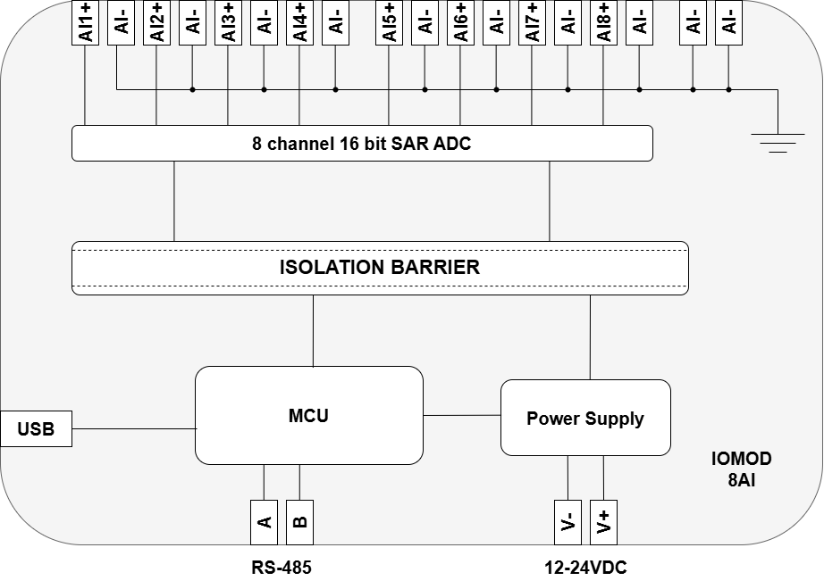
Fig. 1.2.1 IOMOD 8AI internal structure and block diagram
2. Hardware data
2.1 Mechanical drawings
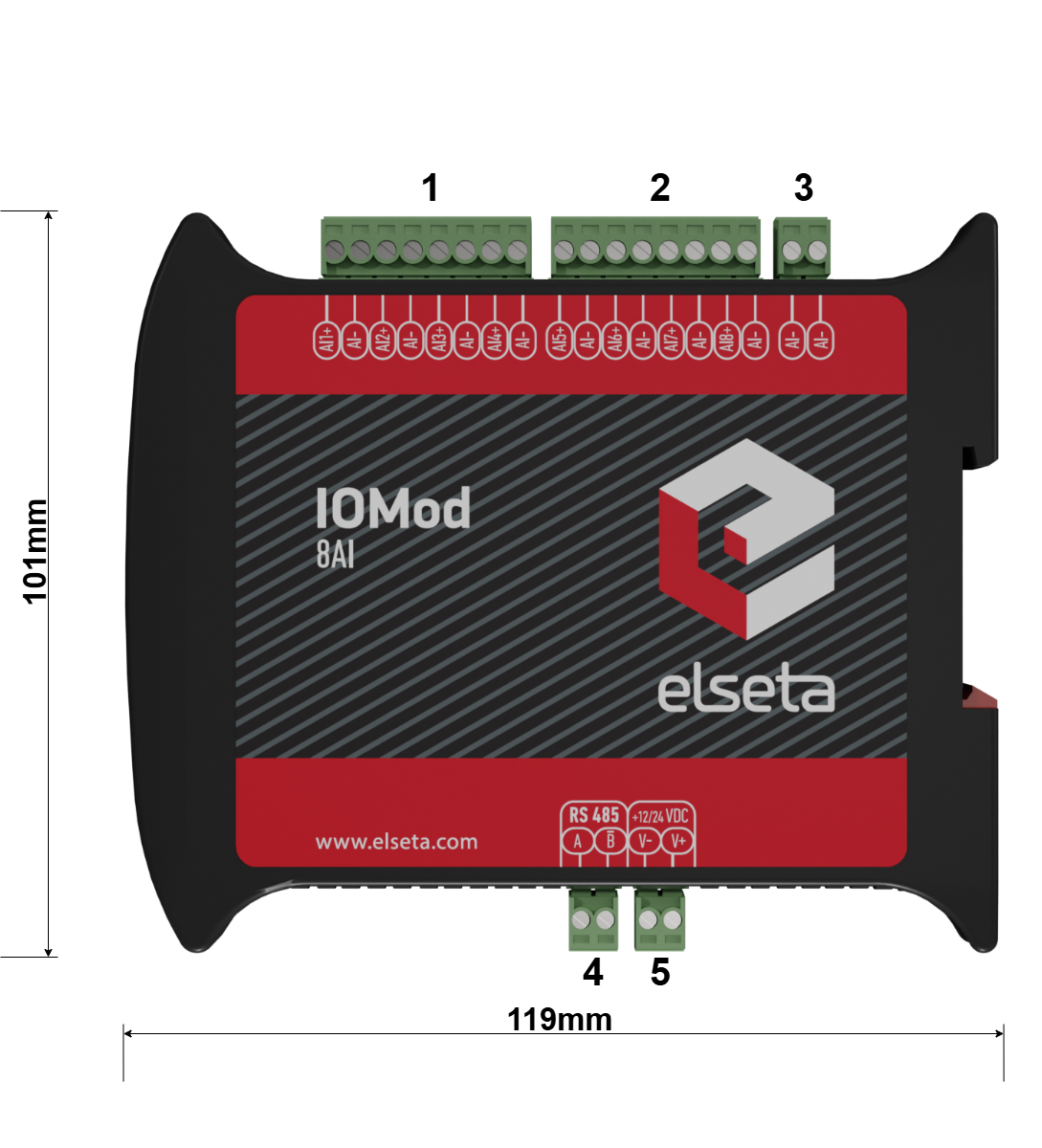
Fig. 2.1.1 IOMOD 8AI side view with dimensions and terminals description. 1 - 2 analog inputs with ground, 3 - Common, 4 - RS485 interface, 5 - power supply input
Fig. 2.1.2 IOMOD 8AI front view with measurements
2.2 Terminal connections
IOMod 8AI has 22 terminals, which are depicted below:
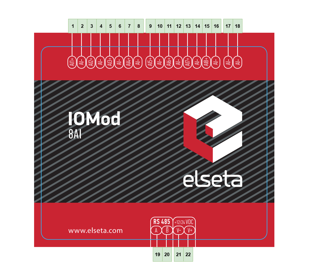
Fig. 2.2.1 IOMod 8AI terminal diagram
The description of each terminal can be found in the table below:
Table 2.2.1 Terminal Specifications
| Terminal number | Terminal name | Description |
| 1 | AI1+ | Analog input 1 |
| 2 | AI- | Common |
| 3 | AI2+ | Analog input 2 |
| 4 | AI- | Common |
| 5 | AI3+ | Analog input 3 |
| 6 | AI- | Common |
| 7 | AI4+ | Analog input 4 |
| 8 | AI- | Common |
| 9 | AI5+ | Analog input 5 |
| 10 | AI- | Common |
| 11 | AI6+ | Analog input 6 |
| 12 | AI- | Common |
| 13 | AI7+ | Analog input 7 |
| 14 | AI- | Common |
| 15 | AI8+ | Analog input 8 |
| 16 | AI- | Common |
| 17 | AI- | Common |
| 18 | AI- | Common |
| 19 | A | RS485 input |
| 20 | B̄ | |
| 21 | V- | Power source input |
| 22 | V+ |
2.3 Status indication
IOMod 8AI has two LEDs, which are used to indicate communication and power statuses.
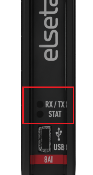
Fig. 2.3.1 IOMod 8AI LEDs physical location
The description of each IOMod 8AI LED can be found in the table below:
Table 2.3.1 Description of LEDs
|
Name |
LED color |
Description |
|
RX/TX |
🟢 (green) |
A blinking green light indicates active communication via the RS485 interface. |
|
STAT |
🟢 (green) |
The power source is connected to the power supply input. |
|
🔵 (blue) |
IOMod 8AI is connected to an external device via a USB mini cable. |
3. Technical information
Table 3.1. Technical specifications.
| System | |
| Dimensions | 17.5 (H) x 101 (W) x 119 (L), mm |
| Case | ABS, black |
| Working environment | Indoor |
| Working temperature | -40°C ... +85°C |
| Recommended operating conditions |
5 – 60°C and 20 – 80%RH; |
| Configuration | USB, RS485 |
| Firmware upgrade | USB, RS485 |
| Electrical specifications | |
| Inputs | 16-bit resolution; Channel-Independent Programmable Input Ranges: ● Voltage input: ○ Bipolar: ±10.24 V, ±5.12 V, ±2.56 V ○ Unipolar: 10.24 V, 5.12 V ● Current input: ○ Bipolar: ±45.5 mA, ±22.75 and ±11.38 mA ○ Unipolar: 45.5 mA, 22.75 mA Overvoltage protection up to ±20V; |
| Power | |
| Power Supply | 9 - 33 VDC |
| Current consumption | 40mA @ 12VDC, 20mA @ 24VDC |
4. Mounting and installation
4.1 IOMOD 8AI inputs
A typical application of IOMod 8AI unipolar and bipolar voltage inputs is shown in Fig. 4.1.1
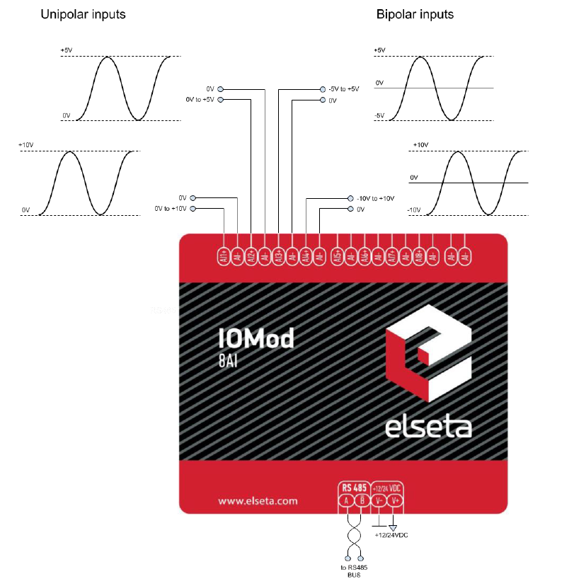
Fig. 4.1.1 Voltage input connection diagram for IOMod device
All analog inputs can be configured as current inputs to connect 0-20 mA, 4-20 mA or other current output sensors. Typical application of IOMod 8AI unipolar and bipolar current inputs is shown in Fig. 4.1.2.
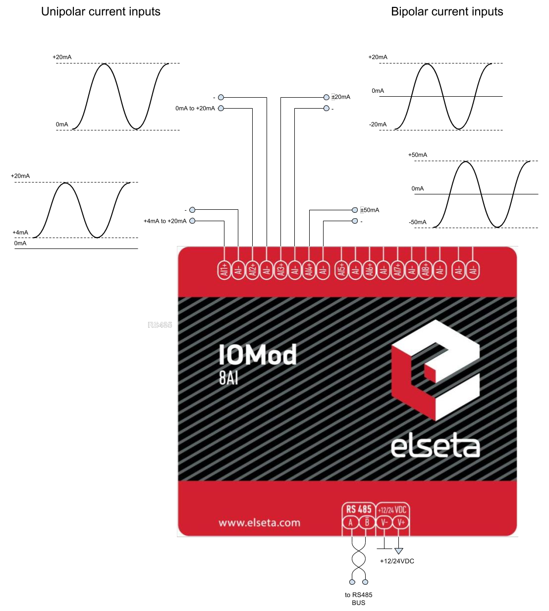
Fig. 4.1.2 Current input connection diagram for IOMod device
4.2 Power connection
IOmod 8AI can be powered through the main power connector +12/24 VDC or USB. Apply 12/24VDC power supply to the V+ and V- terminals. The device has a built-in reverse voltage polarity, overcurrent and overvoltage protection.
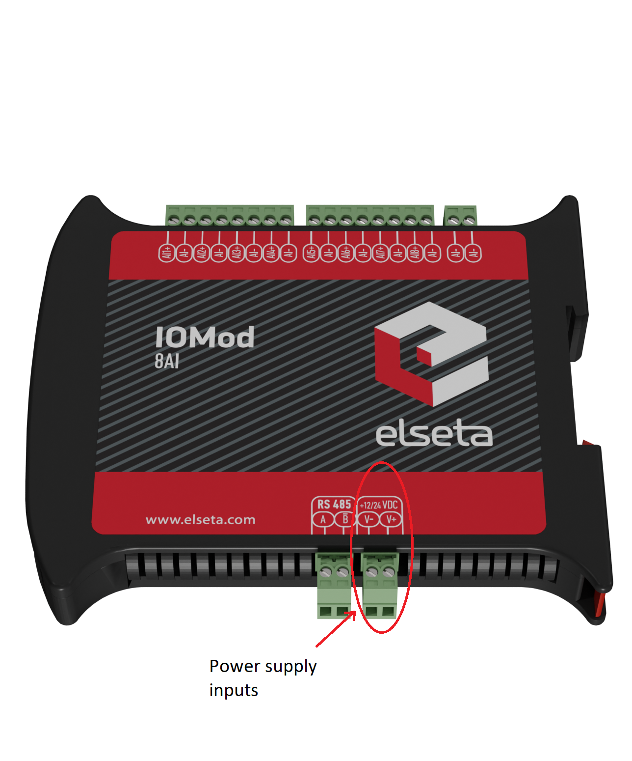
Fig. 4.2.1 Power supply inputs physical location
4.3 USB connection
IOMod 8AI device has a USB-mini connection port. Its primary function is the physical connection establishment between the IOMod and a PC. By selecting the USB interface and correct communication port in IOMod Utility (Fig. 4.3.1) a user can connect to the IOMod to control its parameters and monitor its measured data.
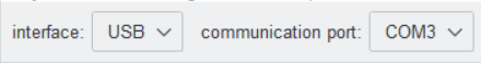
Fig. 4.3.1 IOMod Utility interface and communication port parameters
![]()
Fig. 4.3.2 IOMod 8AI USB connection port physical location
5. Parametrization
In this section, the IOMOD 8AI settings configuration is described. IOMOD 8AI configuration is performed via IOMod Utility (the manual can be accessed here). All IOMOD-related settings can be found in the "Iomod settings" tab (Fig. 5.1).

Fig. 5.1 IOMod settings tab
5.1 IOMod settings
In this section are described all the measurement parameters of the device. The first 3 subsections show all the parameters that are specific to each protocol and the forth one is for general parameters that all of them share.
5.1.1 IOMod Modbus measurement parameters
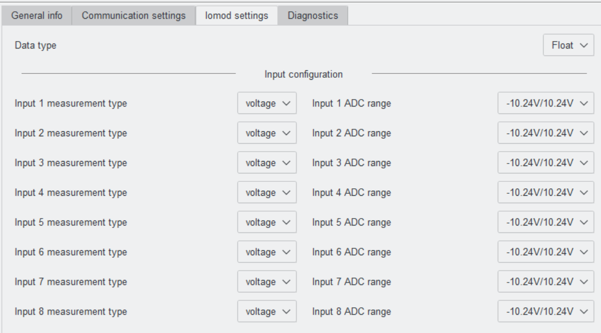
Fig. 5.1.1.1 IOMod settings for Modbus, showing data type and input configuration
Table 5.1.1.1 IOMod Modbus parameter ranges and default values
| Parameter | Range | Default value |
| Data type |
Float, Unsigned 16 |
Float |
5.1.2 IOMod IEC 60870-5-101 measurement parameters
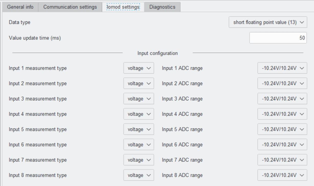
Fig. 5.1.2.1 IOMod settings for IEC 60870-5-101, showing data type and input configuration
Table 5.1.2.1 IOMod IEC 60870-5-101 parameter ranges and default values
| Parameter | Range | Default value |
| Data type |
scaled value (11), short floating point value (13) |
short floating point value (13) |
| Value update time (ms) | 10 - 65535 | 50 |
5.1.3 IOMod IEC 60870-5-103 measurement parameters
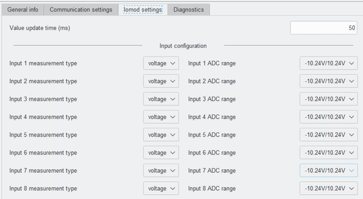
Fig. 5.1.3.1 IOMod settings for IEC 60870-5-103, showing data type and input configuration
Table 5.1.3.1 IOMod IEC 60870-5-103 parameter ranges and default values
| Parameter | Range | Default value |
| Value update time (ms) | 10 - 65535 | 50 |
5.1.4 IOMod general measurement parameters
Table 5.1.4.1 IOMod 8AI parameter ranges and default values
| Parameter | Range | Default value |
| Input [ ] measurement type | voltage, current | voltage |
| Input [ ] ADC range (voltage) |
-10.24V/10.24V, -5.12V/5.12V, -2.56V/2.56V, 0V/10.24V, 0V/5.12V |
-10.24V/10.24V |
| Input [ ] ADC range (current) |
-45.5mA/45.5mA, -22.75mA/22.75mA, -11.38mA/11.38mA, 0mA/45.5mA, 0mA/22.75mA |
-45.5mA/45.5mA |
Value range can be selected to set thresholds on underflow or overflow error statuses. Also, if a scaled integer data type is selected, these limits will be converted to values.
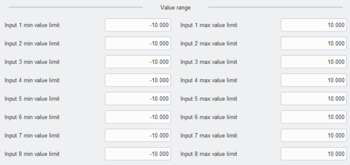
Fig. 5.1.4.1 IOMOD settings sections showing value range
Table 5.1.4.2 IOMOD 8AI parameter ranges and default values
| Parameter | Range | Default value |
| Input [ ] min value limit | float limit | -10 |
| Input [ ] max value limit | float limit | 10 |
Value scaling is where an input value in one range is mapped to a new value in another range. The range for the input is being transformed to another range. Value range and value scaling are related.

The Input Min and Input Max is the value range and Output Min and Output Max is the value scaling. For example, if:
- Input Min = -10
- Input Max = +10
- Output Min = 0
- Output Max = 10
This mapping means:
- An input value of +10 will map to 10 (the upper bound of the mapped range).
- An input value of 0 will map to 5 (the middle of the range).
- An input value of -10 will map to 0 (the lower bound of the mapped range).
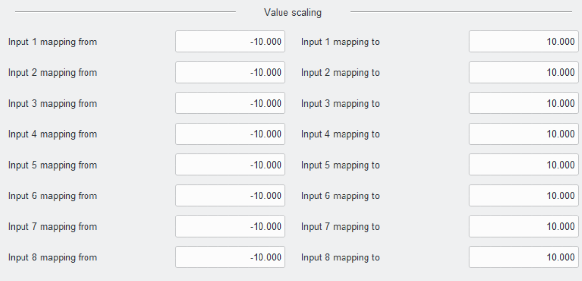
Fig. 5.1.4.2 IOMod settings sections showing value scaling
Table 5.1.4.3 IOMOD 8AI parameter ranges and default values
| Parameter | Range | Default value |
| Input [ ] mapping from | float limit | -10 |
| Input [ ] mapping to | float limit | 10 |
Zero error (%) is the proportion of error (due to a baseline or zero offset) relative to the full-scale range of the signal, expressed as a percentage. For example, IOMOD 8AI will accept a zero error (or offset) of up to 1% (Fig. 5.1.4.3.) of the input signal range before attempting to correct or adjust it.
The averaging coefficient is used to control how many previous measurements contribute to the current value when averaging signals over time. This is typically applied to smooth out noise, reduce fluctuations, or improve the accuracy of readings by averaging multiple data points.
ADC Scan Rate is how frequently the ADC samples and converts the input signal to digital values. It's the rate at which the raw data is being captured by the ADC.
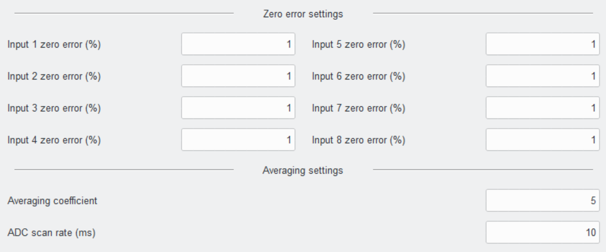
Fig. 5.1.4.3 IOMod settings sections showing zero error and averaging settings
Table 5.1.4.4 IOMOD 8AI parameter ranges and default values
| Parameter | Range | Default value |
| Input [ ] zero error (%) | 1 - 100 | 1 |
| Averaging coefficient | > 0 | 5 |
| ADC scan rate (ms) | >= 2 | 10 |
5.2 Diagnostics
The Utility diagnostics windows allow users to connect to IOMOD directly and observe the values in real-time. The 8AI diagnostics window shows the raw and scaled values.
To turn on real-time monitoring of both Diagnostics sections, the "Connect" button to the left of the "Offline" word designation needs to be pressed. After pressing the "Connect" button the word designation of Diagnostics mode changes to "Online", the black circle starts blinking and the button name changes to "Disconnect" (Fig. 5.2.1).
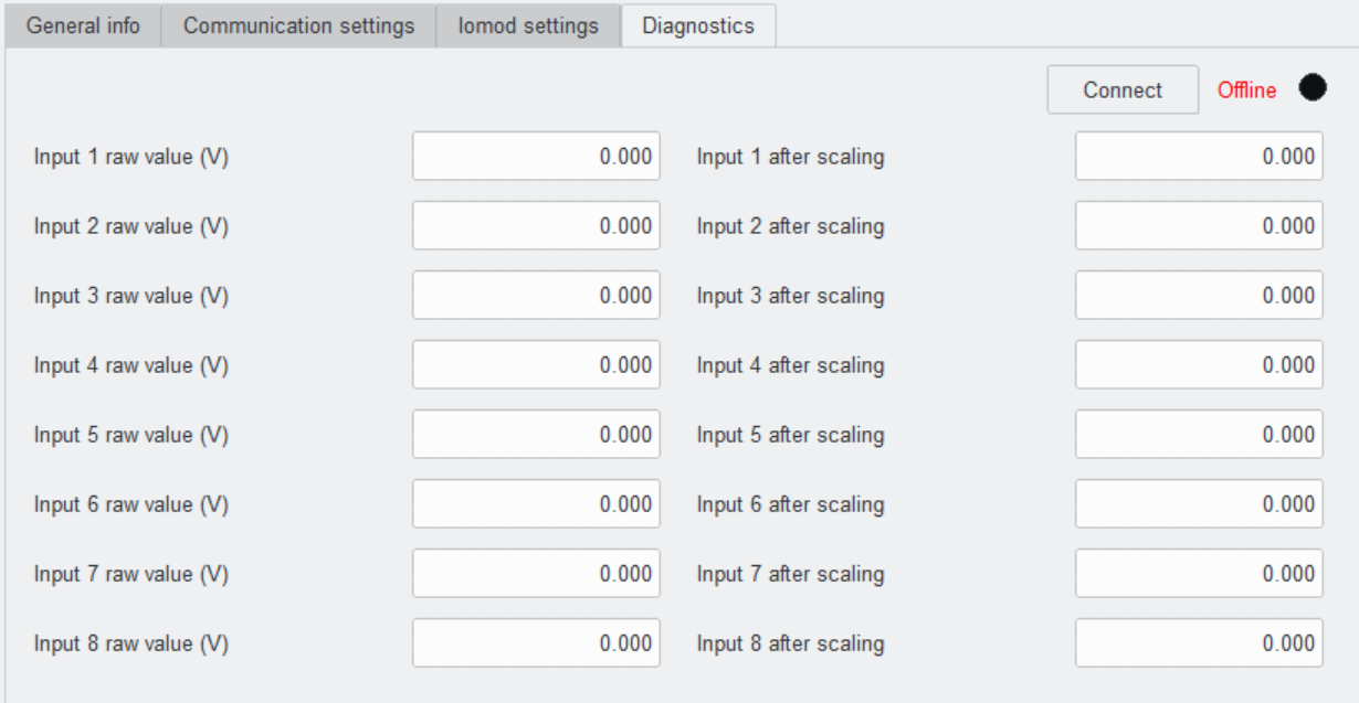
Fig. 5.2.1 IOMod Utility Diagnostics tab in offline mode
6. Communication protocols
The IOMod 8AI supports three communication protocols: Modbus RTU, IEC 60870-5-101, and IEC 60870-5-103. These protocols allow a user, via a master device, to read measured data from the IOMod. The desired communication protocol can be selected using the IOMod Utility application (Fig. 6.1) The Utility's interface allows users to connect to IOMOD via USB port and RS485. More information about this tool and its installation can be found on detailed IOMod Utility manual here.
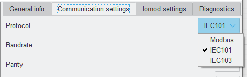 Fig. 6.1 IOMod utility app protocol selection window
Table 6.1 IOMod 8AI protocols default communication settings
|
Protocol |
baudrate |
parity |
stop bits |
wait byte count |
slave address |
link address size |
ASDU size |
COT size |
IOA size |
Input function |
|
Modbus |
19200 | Even | 1 | 8 | 1 | |||||
|
IEC 101 |
19200 | Even | 1 | 8 | 1 | 1 | 1 | 1 | 2 | |
|
IEC 103 |
19200 | Even | 1 | 8 | 1 | 253 | ||||
*Default IOMod 8AI communication protocol is Modbus
6.1 Modbus RTU operational information
Each input can be configured to represent a 16-bit signed integer value or a 32-bit float value. When the float data type is selected, the value will be shown as two registers for one input. When the 16-bit integer data type is selected, a value will be shown as one register. This means addresses of individual input and the maximum number of readable registers can differ according to user configuration.
Configure the device over the IOMod utility. Modbus commands that can be used are shown in the tables below.
02 (0x02) Read Input Status
Used to read analog input overflow and underflow statuses. The first 8 inputs show each input underflow statuses (according to the measurement limits option) and the second 8 inputs show overflow statuses. 0 is the default and 1 means that there's an error (overflow or underflow).
04 (0x04) Read Input Registers
Used to read measurements of at most 8 analog inputs. IOMod 8AI has 8 analog inputs from address 0 to address 15. Different analog inputs can be cast in different data types configured over a USB interface.
Table 6.1.1 Modbus registers for function 2
| Discrete Inputs FC02 |
|||
| Address (Dec) | Description | Data Type | Access |
| 0 | Returns underflow status of input 01 | BOOLEAN | R |
| 1 | Returns underflow status of input 02 | BOOLEAN | R |
| 2 | Returns underflow status of input 03 | BOOLEAN | R |
| 3 | Returns underflow status of input 04 | BOOLEAN | R |
| 4 | Returns underflow status of input 05 | BOOLEAN | R |
| 5 | Returns underflow status of input 06 | BOOLEAN | R |
| 6 | Returns underflow status of input 07 | BOOLEAN | R |
| 7 | Returns underflow status of input 08 | BOOLEAN | R |
| 8 | Returns overflow status of input 01 | BOOLEAN | R |
| 9 | Returns overflow status of input 02 | BOOLEAN | R |
| 10 | Returns overflow status of input 03 | BOOLEAN | R |
| 11 | Returns overflow status of input 04 | BOOLEAN | R |
| 12 | Returns overflow status of input 05 | BOOLEAN | R |
| 13 | Returns overflow status of input 06 | BOOLEAN | R |
| 14 | Returns overflow status of input 07 | BOOLEAN | R |
| 15 | Returns overflow status of input 08 | BOOLEAN | R |
Table 6.1.2 Modbus registers for function 4
|
Input Register FC04 |
|||
|---|---|---|---|
|
Address (Dec) |
Description |
Data type* |
Access |
|
0 |
Input 1 value |
UINT16 |
R |
|
0-1 |
FLOAT | ||
|
2 |
Input 2 value |
UINT16 |
R |
|
2-3 |
FLOAT | ||
|
4 |
Input 3 value |
UINT16 |
R |
|
4-5 |
FLOAT | ||
|
6 |
Input 4 value |
UINT16 |
R |
|
6-7 |
FLOAT | ||
|
8 |
Input 5 value |
UINT16 |
R |
|
8-9 |
FLOAT | ||
|
10 |
Input 6 value |
UINT16 |
R |
|
10-11 |
FLOAT | ||
|
12 |
Input 7 value |
UINT16 |
R |
|
12-13 |
FLOAT | ||
|
14 |
Input 8 value |
UINT16 |
R |
|
14-15 |
FLOAT | ||
*Depends on Data type settings set on IOMod
6.2 IEC 60870-5-101 operational information
Table 6.2.1 IEC 60870-5-101 registers
|
IOA |
Name |
TI* |
|
1 |
input 1 value |
11 (M_ME_NB_1) or 13 (M_ME_NC_1) |
|
2 |
input 2 value |
11 (M_ME_NB_1) or 13 (M_ME_NC_1) |
|
3 |
input 3 value |
11 (M_ME_NB_1) or 13 (M_ME_NC_1) |
|
4 |
input 4 value |
11 (M_ME_NB_1) or 13 (M_ME_NC_1) |
|
5 |
input 5 value |
11 (M_ME_NB_1) or 13 (M_ME_NC_1) |
|
6 |
input 6 value |
11 (M_ME_NB_1) or 13 (M_ME_NC_1) |
|
7 |
input 7 value |
11 (M_ME_NB_1) or 13 (M_ME_NC_1) |
|
8 |
input 8 value |
11 (M_ME_NB_1) or 13 (M_ME_NC_1) |
*Depends on data type settings set on IOMod: scaled value or short floating point value. Default is short floating value(13)
IOmod uses a standard IEC-60870-5-101 communication scheme. Initiation, control messages, and queries are initiated by the master (controlling station), while the IOMod device (controlled station) only answers these requests. Therefore, the first message should be sent by the master to start/restart communication (ResetOfRemoteLink). This message is answered by IOMod with an acknowledgement (ACK) to enable the master to proceed with sending other messages defined by the IEC-60870-5-101 protocol.
Time synchronization is critical for logging events. To synchronize time, the master sends a Time Sync command C_CS_NA_1 (103) with Cause of Transmission (COT) 6. According to the IEC 60870-5-101 protocol specification, time synchronization can be performed for multiple devices using broadcast messages. A master device sends a broadcast timesync command with a broadcast link address. This ensures consistent time-stamping for event recording and fault detection across the network.
General Interrogation (GI) is initiated by the master sending the General Interrogation command. The command type is C_IC_NA_1 (100) and the Cause of Transmission (COT) has to be 6. The command has to be sent to the correct link address and CASDU, which is the same as the link address by default. If the sent frame is correct the IOMod will respond with a C_IC_NA_1 (103) type command with the COT (cause of transmission) of 7 and the p/n bit will be positive (0). Otherwise, it will respond with the same command just that the p/n bit will be negative (1). Then the device will begin to send all of its data. After that's done the IOMOD will also send another 100 type command with the COT (cause of transmission) of 10 (ActTerm) meaning the general interrogation is over.
6.3 IEC 60870-5-103 operational information
Table 6.3.1 IEC 60870-5-103 registers
|
Type |
INF |
FUN |
Description |
|
3 (M_MEI_NA_3) |
0 |
253 |
input 1 value |
|
3 (M_MEI_NA_3) |
1 |
253 |
input 2 value |
|
3 (M_MEI_NA_3) |
2 |
253 |
input 3 value |
|
3 (M_MEI_NA_3) |
3 |
253 |
input 4 value |
|
3 (M_MEI_NA_3) |
4 |
253 |
input 5 value |
|
3 (M_MEI_NA_3) |
5 |
253 |
input 6 value |
|
3 (M_MEI_NA_3) |
6 |
253 |
input 7 value |
|
3 (M_MEI_NA_3) |
7 |
253 |
input 8 value |
As IOMod 8AI doesn’t have any digital inputs, only analog ones, general interrogation returns nothing. Values of measurements are returned cyclically without any additional request therefore commands sent will be ignored.
Time synchronization is critical for logging events. To synchronize time, the master sends a Time Sync command with function 0 and Cause of Transmission (COT) 8. According to the IEC 60870-5-103 protocol specification, time synchronization can be performed for multiple devices using broadcast messages. For broadcast time synchronization, the master device sends a periodic signal with a time stamp to synchronize the system time of slave devices. If synchronization fails, devices default to their local system time until they successfully resynchronize.