IOMOD 8AI User Manual Modbus
Introduction
IOMod 8AI is a compact-sized stand-alone Modbus (RTU) or IEC-60870-5-103 analog input controller. IOMod can be used for industrial applications where digital signaling is used and robust communication is needed. IOMod is an ideal solution for applications such as data acquisition, observation, process monitoring, testing and measurement at remote places. It is controlled over Modbus or IEC 60870-5-103 protocol, and can be used with any SCADA system.
Features
● 8 analog inputs, each configurable separately
● All inputs are capable of measuring electrical voltage or current
● Inputs can be recalibrated according to the needs of a user
● RS485 communication
● LED input indications, + Data transmission (Rx and Tx) indication.
● Configurable over USB
● Drag-and-Drop firmware upgrade over USB
● A small sized case with removable front panel
● DIN rail mount
● Operating temperature: from -30 to +70°C
● Power Requirements: 12-24 VDC
Operational Information
IOMod 8AI uses Modbus (RTU) or IEC 60870-5-103 protocol over RS485 interface. A protocol used by a device can be changed by uploading corresponding firmware. Default communication settings: 9600 baud/s baud rate, 8N1 port configuration, Slave address - 1.
Common configuration information
- Measurement type. A user can select measurement type (electrical current or voltage) on each channel individually.
- Sensitivity selection. To increase a resolution of input measurement capture, a user can define in which range measurement will occur. The best resolution will be achieved within a shortest selected range. For all possible configurations refer to Technical Information and Configuration over USB described later in this document.
- Measurement limits can be selected, which in turn set thresholds on underflow or overflow error statuses. Also, if a scaled integer data type is selected, these limits will be converted to values using limits stated in Casting data range for Modbus protocol.
- Data type selection. A device can output float or scaled integer data types for each input individually for Modbus. Modbus input register read will then show raw float value (in milliamperes or millivolts) or scaled integer types. When a float data type is selected, each input will be represented as two Modbus registers (32-bits). These values can be later
converted to IEEE-754 standard-compatible float values. - Casting data range. A device is capable of converting measurements into desired decimal values in a linear manner. For Modbus, a user can select between floating point data type – which will return a raw measurement of either voltage or current and scaled integer type – which conversion is freely definable. Note that the specification for IEC-60870-5-103 only lets 13-bit signed measurands, therefore only cast representation of true value can be used with absolute limits being [-4095, 4095].
Fig. 3.2 shows how raw measurement (current in this case) is converted to an integer type. Conversion is done by defining measurement limits (from -25mA to 25mA) and casting data range (from 0 to 100). Measurement limits define thresholds for overflow and underflow errors respectively; casting data range defines limits (from 0 to 100) that value should be between after recalculation. Such a recalculation can be used in applications that require measurements in relative units such as percentage.
A device can round measurements to lower conversion limit (in this case – to zero) if a measurement is near it: ±15% of measurement value (Fig. 3.2). Live zero correction is a useful option for eliminating noise. As signals always have some noise level, such an option can compensate it to get a true zero value.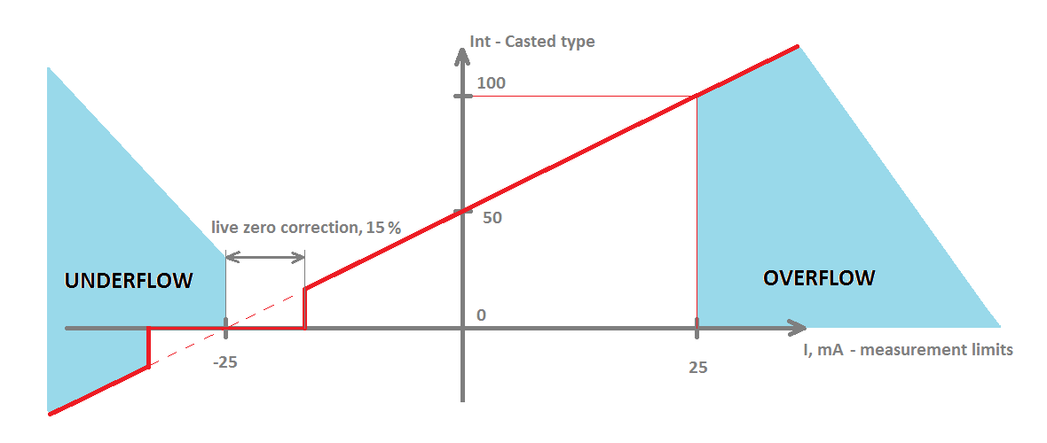

Fig. 3.2. Conversion graph from raw measurement to cast integer
MODBUS operational information
Each input can be configured to represent 16-bit signed integer value or 32-bit float value. When the float data type is selected, the value will be shown as two registers for one input. When the 16-bit integer data type is selected, a value will be shown as one register. This means addresses of individual input and the maximum number of readable registers can differ according to user configuration.
Configure device over USB terminal. Modbus commands that can be used are shown in the table below.
Supported MODBUS functions
02 (0x02) Read Input Status
Used to read analog input overflow and underflow statuses. First 8 inputs show each input underflow statuses (according to measurement limits option) and second 8 inputs show overflow statuses.
04 (0x04) Read Input Registers
Used to read measurements of at most 8 analog inputs. IOMod 8AI has 8 analog inputs from address 0 to address 15 (0000Fh). Different analog inputs can be cast in different data types configured over a USB interface.
02 (0x02) Read Input Status
Used to read analog input overflow and underflow statuses. First 8 inputs show each input underflow statuses (according to measurement limits option) and second 8 inputs show overflow statuses. 04 (0x04) Read Input Registers
Used to read measurements of at most 8 analog inputs. IOMod 8AI has 8 analog inputs from address 0 to address 15 (0000Fh). Different analog inputs can be cast in different data types configured over a USB interface.
Modbus register table
Modbus register table
| Function | Register | Name | Description | Values range |
| 02 | 00000-0000F | Read Input Status | Returns overflow and underflow statuses of each input. First 8 shows underflow status, last 8 shows overflow | 0 – OK, 1 - error |
| 04 | 00000-0000F | Read Input Registers | Returns Input values |
0-65535 (decimal) of one Register |
Technical information
| System | |
| Dimensions | 101 x 119 x 17.5 mm |
| Case | ABS, black |
| Working environment | Indoor |
| Working temperature | -30°C +70°C |
| Recommended operating conditions |
5 – 60°C and 20 – 80%RH; |
| Configuration | USB |
| Firmware upgrade | USB – mass storage device |
| Electrical specifications | |
| Inputs | 16-bit resolution; Channel-Independent Programmable Input Ranges: ● Voltage input: ○ Bipolar: ±10.24 V, ±5.12 ±2.56 V ○ Unipolar: 10.24 V, 5.12 ● Current input: ○ Bipolar: ±45.5 mA, ±22.75. and ±11.38 mA ○ Unipolar: 45.5 mA, 22.75 Overvoltage protection up to ±20V; |
| Power | |
| Power Supply | 9V to 33V |
| Current consumption | 40mA @ 12VDC, 20mA @ 24VDC |
Mounting and installation guide
IOMod 8AI RS485 interface
IOMod 8AI has integrated 120Ω termination resistor which can be enabled or disabled over USB configuration. It is recommended to use termination at each end of the RS485 cable. See typical connection diagram in Fig. 5.1.
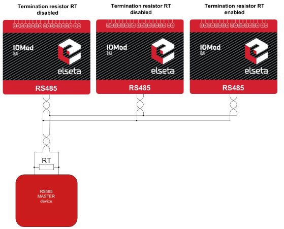
Fig. 5.1. Typical IOMod connection diagram
IOMod 8AI has 1/8 Unit load receiver which allows having up to 255 units on a single line (compared to standard 32 units). To reduce reflections keep the stubs (cable distance from main RS485 bus line) as short as possible.
IOMod 8AI inputs
A typical application of IOMod 8AI unipolar and bipolar voltage inputs is shown in Fig. 5.2. See Configuration over USB chapter for instructions for analog input configuration.

Fig. 5.2. Voltage input connection diagram for IOMod device
All analog inputs can be configured as current inputs to connect 0-20 mA, 4-20 mA or other current output sensors. Typical application of IOMod 8AI unipolar and bipolar current inputs is shown in
Fig. 5.3. See Configuration over USB chapter for instructions for analog input configuration.

Fig. 5.3. Current input connection diagram for IOMod device
Configuration over USB
Driver installation
The device requires USB drivers to work as a Virtual COM port. The first-time connection between
device and computer could result in “Device driver software was not successfully installed” error
(as in Fig. 6.1).
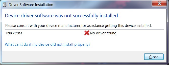
Fig. 6.1. Unsuccessful device software installation error
A user then should manually install drivers by selecting a downloaded driver folder:
- Go to Control Panel -> Device Manager;
- Select a failing device;
- Press “Update driver software”; screen as in Fig. 6.2. should appear:
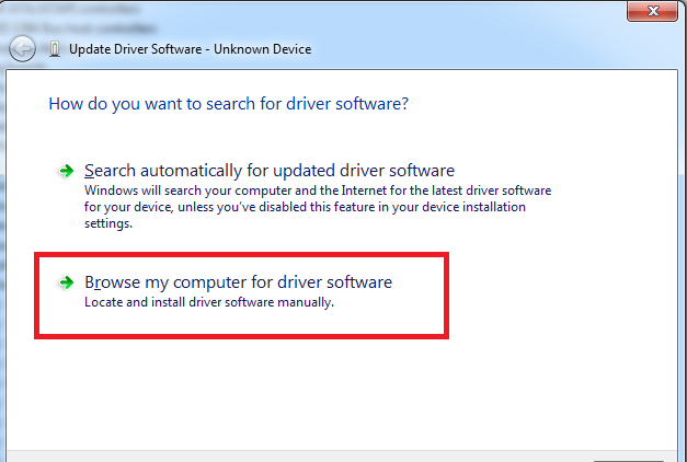
Fig. 6.2. Device driver software update message
- Select “x86” driver for a 32-bit machine or x64 for a 64-bit machine. If not sure, select a root
folder (folder in which x64 and x86 lay inside, as in Fig. 6.3).
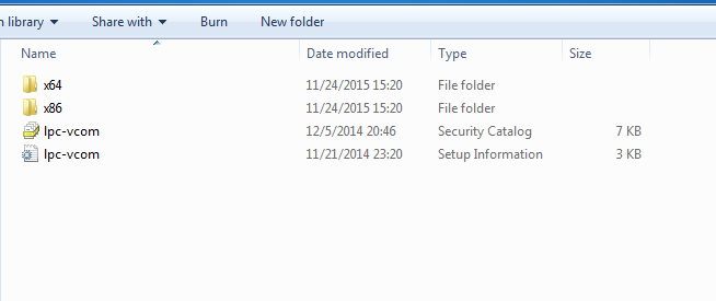 Fig. 6.3. Device driver folder content
IOMod configuration via PuTTY terminal
A configuration of IOMod device is done through CLI (Command Line Interface) on the virtual COM port. Drivers needed for Microsoft Windows to install VCOM will be provided. To open up CLI simply connect to specific V-COM port with terminal software (advised to use PuTTY terminal software. If other software is being used, a user might need to send <return> symbol after each command). When connected user should immediately see the main screen.
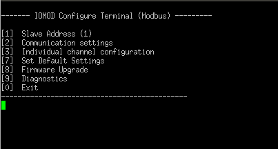 Fig. 6.4. The main menu for IOMod 8AI, Modbus firmware version
If the terminal window is closed accidentally, a user can connect the terminal program again, and press any key on a keyboard to show the main menu again.
|
Menu Name |
Function |
Values |
Default Values |
|
| 1. |
Slave Address |
Modbus Slave address / ID |
1-247 |
1 |
| 2. |
Communication settings |
[1] Baud rate, [2] Data, Stop and Parity Bits, [3] RS485 Terminating resistor |
[1] 100 - 256000, [2] 8 Data bits + 1/2 Stop bits, Even/None/Odd Parity [3] Enabled/Disabled |
[1] 9600, [2] 8N1, [3] Enabled |
| 3. |
Individual channel configuration |
Channel configuration screen (see Table “Individual Channel |
||
| 7. |
Set Default Settings |
Sets Default Settings |
(1 to confirm, 0 to cancel) |
- |
| 8. |
Firmware Upgrade |
Mass Storage Device Firmware Upgrade |
(1 to confirm, 0 to cancel) |
- |
| 9. |
Diagnostics |
Input / Output states |
- |
- |
| 0. |
Exit |
Exit and disconnect |
- |
- |
Individual channel configuration
| MenuName | Function | Values | Default Values |
|
| [1] | Measure Current/Voltage | Selecting this option toggles measurement selection |
- | - |
| [2] | Change sensitivity | Selecting a measurement range |
[1] [-10.24 V, 10.24 V], [2] [-5.12 V, 5.12 V], [3] [-2.56 V, 2.56 V], [4] [0 V, 10.24 V], [5] [0 V, 5.12 V] |
[1] [-10.24 V, 10.24 V] |
| [3] | Measurement limits | Entering floating point values to use them for marking overflow/underflow statuses |
Floating values in a range defined by measuring sensitivity |
-5 mV; 5mV |
| [4] | Cast to a scaled integer/float | Selecting this option toggles value casting selection |
||
| [5] | Casting data range | Check Common configuration information |
||
| [6] |
Live zero tolerance | |||
| 0 | Back | Back to last menu screen |
||
Measurements’ calibration
Every device is shipped containing factory-predefined calibration coefficients. However, changing temperature and humidity conditions can affect the accuracy of measurements. To get the best accuracy, use the device at room temperature and if that is not possible, calibrate coefficients accordingly.
To enter the calibration screen (Fig. 6.6) from main menu press ‘@’ symbol.
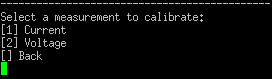
Fig. 6.6. Analog inputs’ calibration screen
In the calibration screen, either current or voltage coefficients can be selected. Selecting current by pressing [1] should enter additional screen (Fig. 6.7). Calibrating voltage is an identical process therefore only current setting is explained.
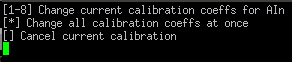
Fig. 6.7. Current calibration screen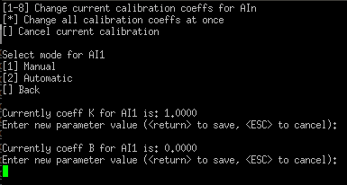
Fig. 6.8. Manual calibration coefficients’ setting
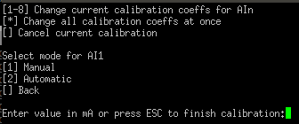
Fig.6.9. Automatic calibration coefficients’ setting
All configuration coefficients can either be configured all at once or individually. The coefficient setting for all channels is done manually only. Tweaking individual channels, however, can be automatic (Fig. 6.9) as well as manual (Fig. 6.8). Selecting automatic calibration polls values that user inputs and tweaks coefficients to minimize the additive error. It is therefore advised to scan several values differing by the same value interval to get the best results. Pressing ESC finishes calibration and saves coefficients to non volatile memory.
Protocol simulation over USB
After entering the diagnostics screen, protocol simulator can be turned on by pressing [9]. When it is on, the device will communicate over USB port rather than a RS-485 line. Communication on a RS-485 line is closed and all Modbus or IEC-60870-5-103 commands will only be accepted from USB. To exit this mode device must be restarted.
Firmware upgrade over USB
To update device firmware user must enter main configuration menu.
Enter Firmware update screen by pressing [8];
Confirm update by pressing [1];
Device now enters Firmware Upgrade mode. Device reconnects as mass storage device (Fig 6.10.).
 It is recommended to close terminal window after entering firmware upgrade mode.
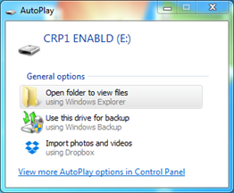 Fig. 6.10. Mass storage device warning
User then must delete existing file “firmware.bin”, and simply upload new firmware file by drag and drop. (Fig 6.11.)
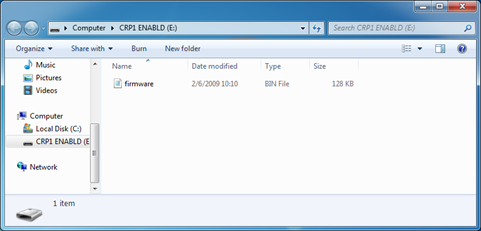 Fig. 6.11. Dragging and dropping new firmware file
Reconnect device and check firmware version. It should now represent the one it was updated to.
Testing With “THE VINCI” software
To test IOMod with default settings, a device should be connected through RS485 to Modbus master. Example using “The Vinci Expert” device as serial interface converter and adapter to PC with “The Vinci” software. Default settings for Modbus – 9600 baud/s baud rate; 8 data, no parity, 1 stop bit. When opening “The Vinci” software, choose Modbus serial – Master mode. In the Settings tab, choose station number (default – 1); configure tags (as described in section Modbus operational information); Press Start and go to “Statistic” tab as shown in Fig. 7.1.

Fig. 7.1. Testing IOMod Modbus communication using “THE VINCI” software
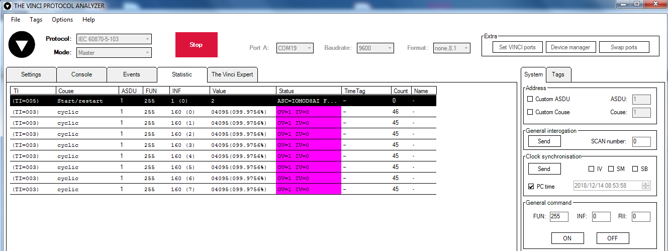 Fig. 7.2. Testing IEC-60870-5-103 communication using “THE VINCI” software