User Manual
Introduction
MV Beacon is a device used to send SMS messages about emergency conditions from external
sensors and short circuit indicators in medium and low voltage substations. Easy to install and
especially popular with transmission network operators. MV Beacon is designed to monitor the
electrical condition of airline lines, short-circuit measurement in airline cables, and also has a long
service life – battery life is up to 8 years.
The MV Beacon can be used together with the WCC200 data collection device as a central router for
receiving SMS messages and a protocol converter to industrial protocols (IEC 60870-5-101, IEC
60870-5-103, IEC 60870-5-104, SNMP, Modbus RTU/ ASCII, Modbus TCP). Using WCC200 routers,
the customer can easily integrate up to 256 units. MV Beacon to SCADA system.
General product information
MV Beacon is designed for monitoring four discrete digital inputs and sending their status via SMS
messages.
In order to ensure a long operating time, the device goes into sleep mode and wakes up from a
discrete input signal change or from a periodic check (Heartbeat). After each SMS message sent, the
device switches to Standby mode, where it waits for new events or configuration SMS messages. In
this mode, the MV Beacon stays on for a user-defined time and then returns to sleep mode.
Outgoing SMS messages can contain event (EVENT), device name (ID), message counter (CNT),
input values (I1-I4), battery voltage level (BAT), signal quality (GSQ), date and time information.
Two modifications of MV BEACON are produced:
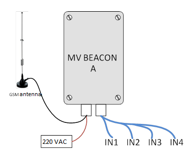
MV BEACON A is a device powered directly from the 230 VAC mains, with an internal UPS
(uninterruptible power supply) with a 2.6 Ah lithium-ion battery. Suitable for operation in substations, in
places where monitoring of several discrete signals is required at the same time.
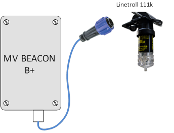
MV BEACON B+ is a device powered by internal 3.6 V, 22 Ah lithium-ion batteries. The signal cable is connected directly to the Linetroll 111k sensor. Suitable for operation in remote areas. Mounted to the line support. The set includes MV BEACON and 5 meters of special cable for connecting the Linetroll 111k sensor.
MV BEACON body tightness class IP-64. This means that the device is protected from any impact of dust and water drops in all directions.
Product documentation
-
MV BEACON service manual
-
MV BEACON operational documentation
-
MV BEACON passport
Functions
4 discrete logic inputs
• Power failure message (AC version)
• Active level inversion function for discrete inputs
• Password for configuration and data reading
• Configuration USB interface
• Mobile operator and base station information
• Watchdog function
• IP64 housing tightness class
• GSM signal strength and battery level in each SMS message
• SMS message data reading and configuration in a human-readable format
• Updating the internal MV Beacon program via PC
Operation
When the input signal changes, MV Beacon sends an SMS message to the configured phone
number(s). This can be a dispatcher's mobile phone or a SCADA system. After the message is sent,
the MV Beacon goes into standby mode.
Specific operating intervals can be set, activity messages include device ID, discrete signal levels,
battery voltage level, GSM antenna connection level, date, time information.
MV Beacon is designed to work with:
• Northtroll Linetroll 111k
• Northtroll Cabletroll 2700
Other devices can be connected using relays or optocouplers.
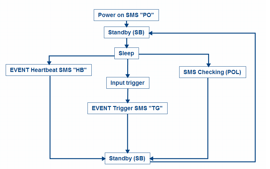
Equipment operation algorithm
1. An "EVENT PO" message is sent when the device is powered on or rebooted.
2. The device goes into standby mode, where it stays for the configured time (see SB (standby));
3. If nothing happens during this time, the device goes into sleep mode;
4. If no configured events occur during the HB or POL intervals (see HB (heartbeat) interval and
see POL (polling)), the device wakes up from sleep at the end of any of these intervals. In case
of HB, an "EVENT HB" message is sent. In the case of POL, the message is not sent, but a
device configuration message is checked from other mobile devices;
5. If the input signal changes while the device is in sleep mode, the device wakes up and sends
an "EVENT TG" message;
6. The algorithm is repeated from point 2.
This algorithm is shown in the figure below
Device discrete input settings
Input triggering is registered after pulses of freely configurable width, but not shorter than 20 ms;
shorter pulses wake up the device (for faster registration of the next input) but are ignored.
Each of these can be inverted (see IE1 – IE4). After inversion, the determined input is displayed
inversely to its connection – if the contact is shorted, a logical zero is fixed; if the contact is released, a
logical unit is displayed. Important: Care must be taken to properly connect the contacts, as the device
may send misleading messages about the input signal.
The device has the ability to send messages about short-term and long-term errors. If this function is
disabled, the device will only send input states (1 or 0); If this function is enabled, the device can send:
0, 1 (short-term error) or 2 (long-term error). A transient error occurs when an input signal goes to an
active level but recovers within a set time (PTD). A permanent error occurs when a transient error
does not recover within a set time interval (PTD (permanent/transient delay)), a second EVENT TG
SMS message is sent. If the PTD time is zero, long-term error transmission is disabled.
Device time interval settings
Heart-beat interval and Poling interval are calculated in hours. These values can be changed from 1 to
720 hours. Standby time is measured in minutes, so the value can be changed from 1 to 60 minutes.
Energy efficiency (device operation time) and the reliability of receiving SMS messages depend on the
value of the standby mode – a longer standby mode will be less energy efficient, but will ensure the
reception of SMS messages. It is recommended to choose the standby time between 7 and 10 minutes. Heartbeat and Polling intervals are linked to device time (T – Time and D – Date). If the time and date auto-calibration fails, the sending of messages associated with Heartbeat/Polling intervals may also fail. If the connection quality at the installation location is poor, it is suggested to turn off the automatic time update and use the time without daylight saving time.
Setting up SIM cards and phone numbers
All numbers used in the configuration must be active. If the number is not used, "0" is entered instead.
The administrator (admin) number is mandatory: if it is not entered, the device is blocked. Numbers
can be entered with "+370"; "370" or "8" prefix. The maximum number length is 14.
If the SIM PIN number is enabled on the card, the user must enter this number in the device settings.
The device is locked before the last attempt to enter the SIM PIN code.
Device name (ID) and password:
The device ID will be written in each message to identify the device; The length of the ID can be up to
15 characters. The password is used when configuring the device via a USB terminal or SMS
messages. Must be 4 characters long. The default password is "ADMV". For greater security, it is
strongly recommended that you change this password to a different one.
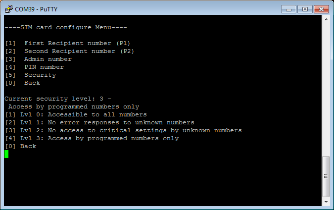
Security setting:
The device has four different security level settings that limit the processing of SMS messages.
Numbers registered in the settings (ADM, P1 and P2) will always receive all SMS messages and will
be able to change all settings. Security levels:
• 0 – communicates with all numbers without restrictions.
• 1 – error responses (ERROR) are not sent to unknown (not recorded in the settings) phone
numbers. For example, when sending the text "AAAA GET HB", only the numbers saved in the
settings will receive the response "ERROR: WRONG PASSWORD"
• 2 – the same as in the 1st security level, but only the registered numbers can set and read the
numbers, password, and security level. For example, sending the text "ADMV SET HB=1" from
an unknown number will change the corresponding setting and the number will receive a
confirmation. However, sending "ADMV SET PASS=1234" will not change the password and
the number will not receive confirmation. Saved numbers can change all settings.
• 3 – communicates only with the specified numbers. All other received messages are ignored.
Technical information
|
System |
MV Beacon A |
MV Beacon B+ |
||
|
1. |
Modem |
U-blox Sara G350, Swiss made 2,5G GSM/GPRS module |
||
|
2. |
Operating frequencies |
Quadband 850/900/1800/1900 MHz |
||
|
3. |
Discreet entrances |
4 DI |
||
|
4. |
Configuration link |
Mini USB |
||
|
5. |
Sensor connection |
Internal terminals |
||
|
6. |
GSM antennas |
Internal/external antenna with 3m cable |
Internal antenna |
|
|
Software functions |
||||
|
1. |
Configuration |
Via USB or SMS |
||
|
2. |
Program update |
Via USB, copying the file on virtual media |
||
|
3. |
Number of SMS users |
Up to 3 users |
||
|
Power supply |
||||
|
1. |
Power supply |
External power source 230 VAC, 85-264 VAC, 47-440 Hz and 2.6 Ah Lithium Ion accumulator |
3.6 V, 22 Ah Lithium Thionyl Chloride battery |
|
|
2. |
Current used |
Up to 130 mA |
||
|
3. |
Battery/accumulator life |
Up to 36 h. |
Up to 8 years |
|
|
Mechanical data |
||||
|
1. |
Measurements |
187(H) x 122 (W) x 90 (L), mm |
||
|
2. |
Body tightness class |
IP65 |
||
|
3. |
Body |
ABS, gray |
||
|
4. |
Operating temperature |
|||
|
5. |
Warranty |
2 years |
||
Preparation for work
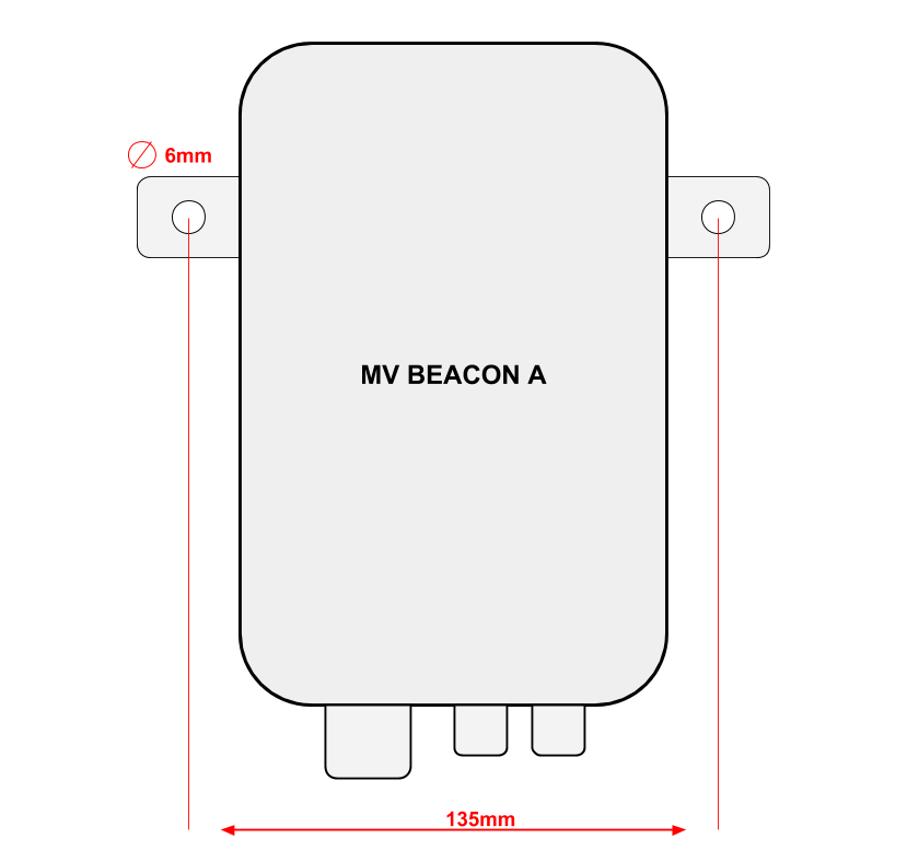
Mounting
MV Beacon A has two attachment points.
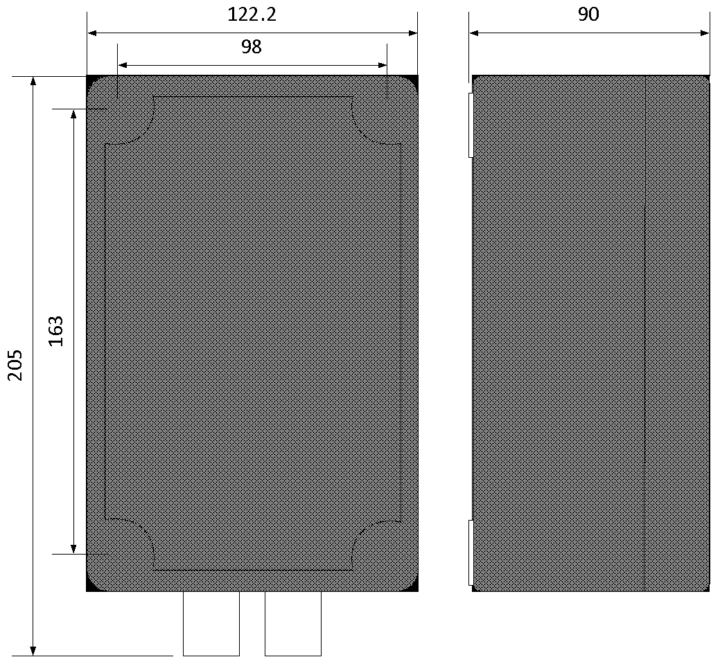
MV Beacon body measurements
Power connection
MV Beacon A Power Connection Instructions:
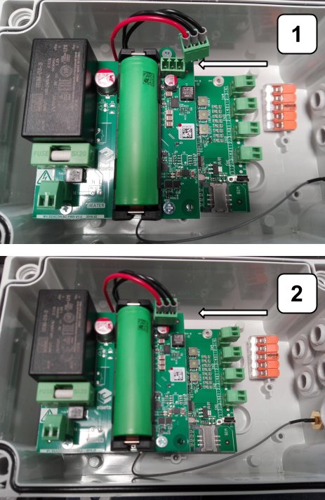
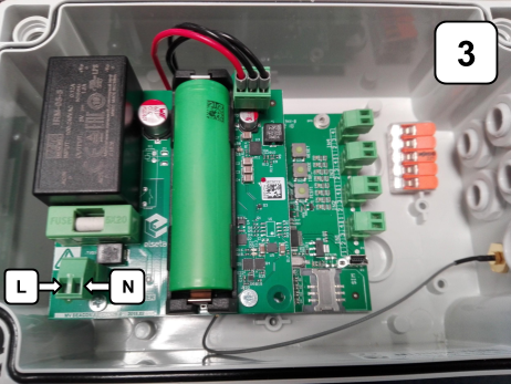
First, connect the three-wire cable as shown in steps 1-2 of the power connection instructions. Using a
2-wire cable, connect the unit's AC power as shown in step 3 of the connection instructions. Turn on
the automatic power switch only when all the work of connecting the device has been completed (SIM
card inserted, input cables connected).
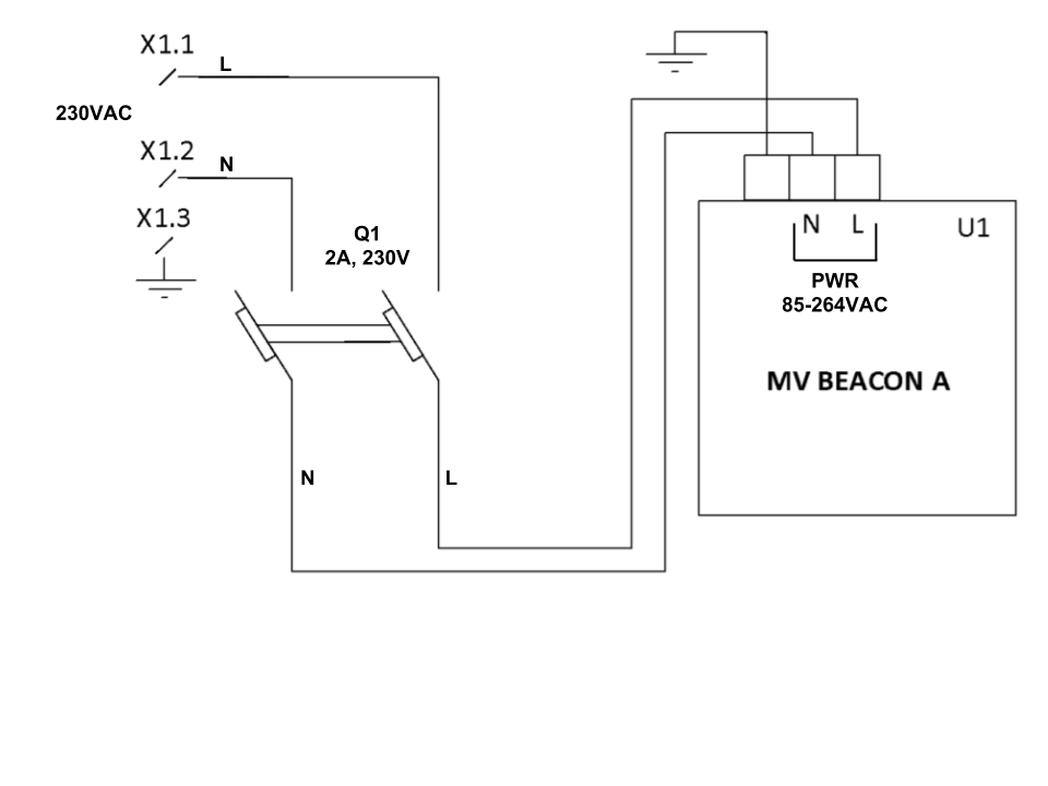
Recommended MV BEACON A power connection diagram
List of components:
X1 terminals
Q1 current automatic switch
U1 MV BEACON A
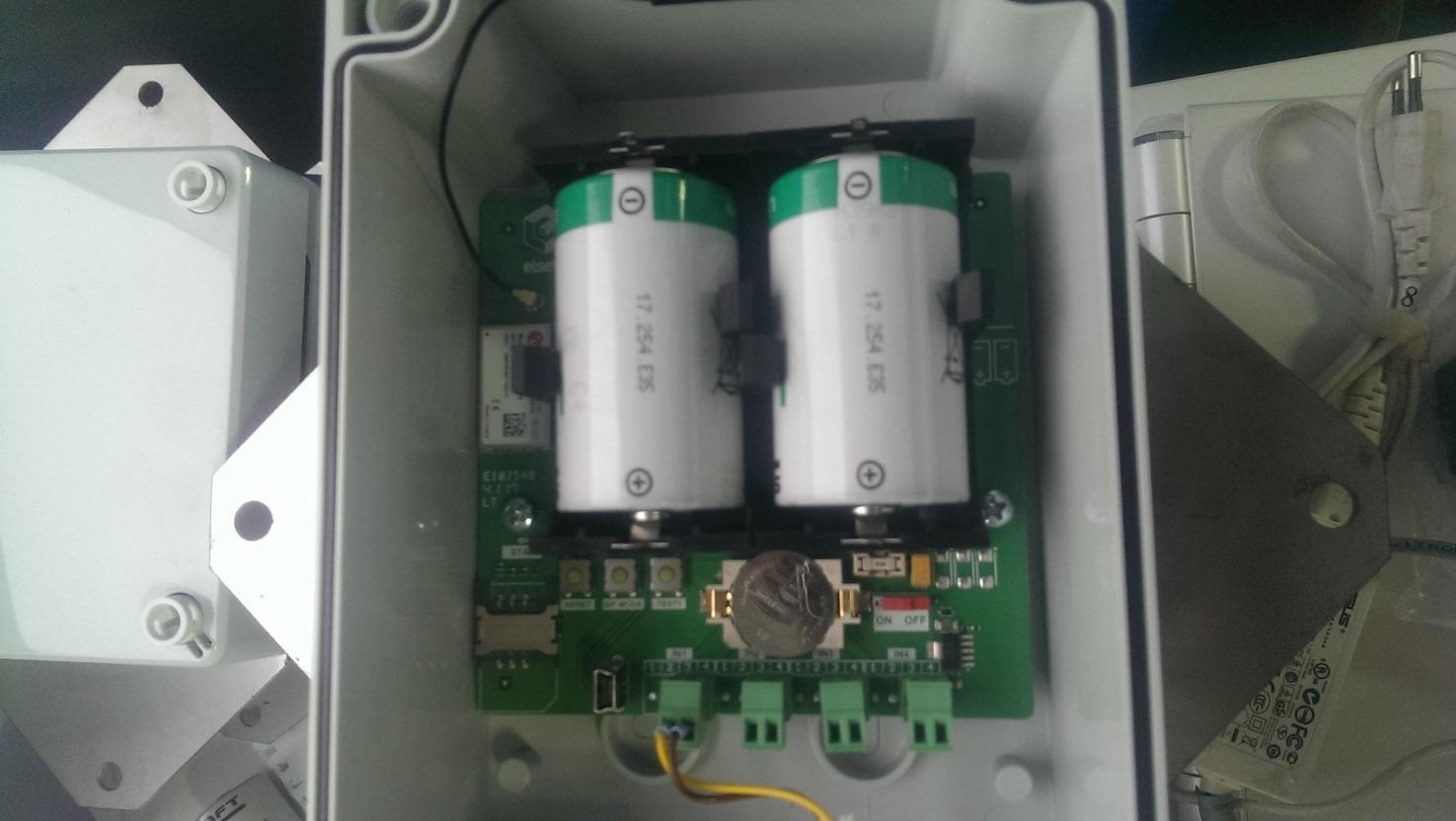
MV Beacon B+ power pin and battery layout
Antenna connection
MV BEACON B+ comes with an internal GSM antenna. If the GSM signal level is not good enough in
the desired area, an external antenna can be used.
MV Beacon A comes with an external GSM antenna. It is suggested to install the GSM antenna taking
into account the coverage quality of the mobile operator at the place of installation. Below is a picture
showing the antenna connection.
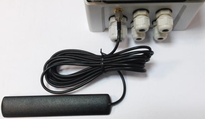
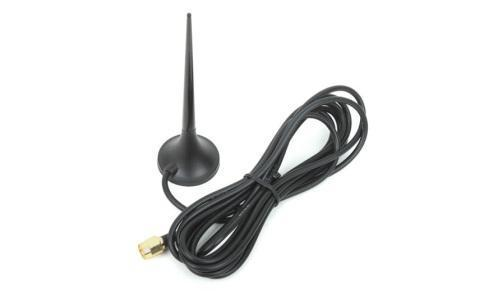
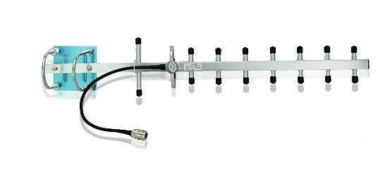
A. B.
Omnidirectional (non-directional) (A) and directional (B) antennas can be used.
Recommended antenna distance to wall or metal objects:

In case of a weak communication signal, it is recommended to use a directional antenna to ensure the
quality of communication transmission.
Installation of SIM card
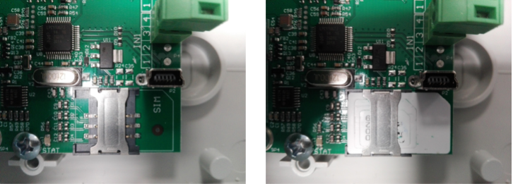
SIM card connection diagram
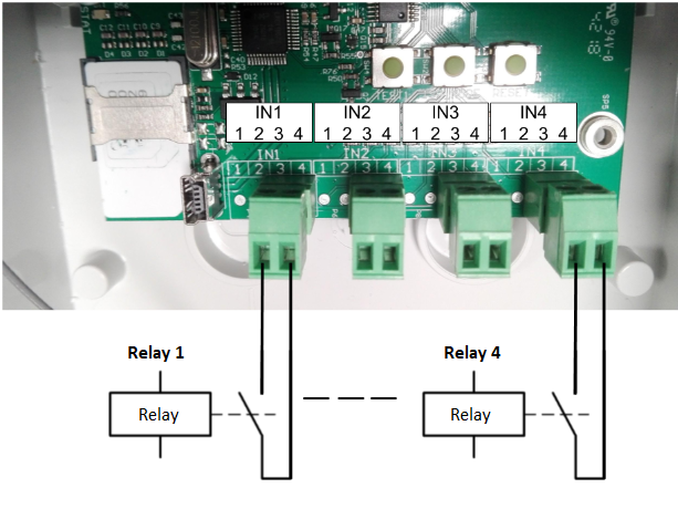
Connection of external sensors
-
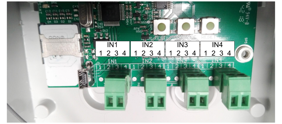
Input contacts 3 and 4 are used to connect the input signal. Methods of transmitting external signals to
MV BEACON: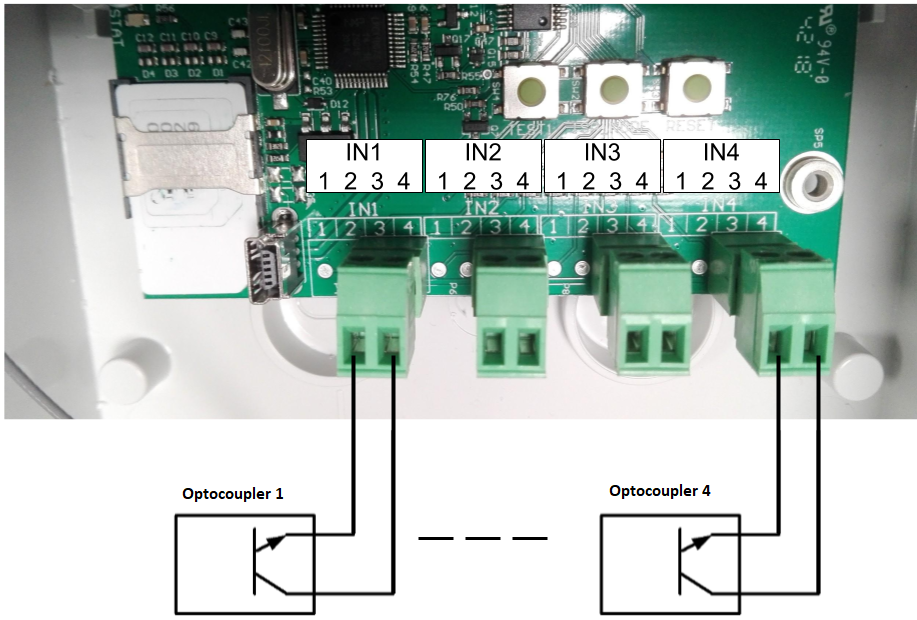

Ground the shields of the signal wires using the terminals shown in the figure below.

Configuration with computer’s USB interface
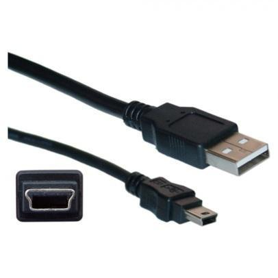
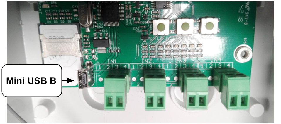
Connecting the configuration cable
MV BEACON configuration works are performed after connecting the equipment to the USB interface
of the computer. A Mini USB(B) to USB(A) type cable is used for this purpose:

Installing drivers on the computer
Device operation requires drivers. When the device is connected for the first time and the operating
system does not find the drivers, a Device driver software was not successfully installed error is
possible.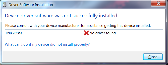
The user must then specify the location of the downloaded drivers on the computer manually:
• Go to Control Panel → Device manager
• Mark the device that failed to install (usually marked with an exclamation mark);
• Choose Update driver software; a selection window should appear: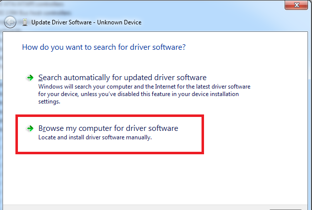
• Choose Browse my computer for driver sofware;
• Find and select driver folders - "x86" for a 32-bit processor or "x64" for a 64-bit processor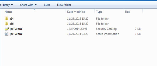
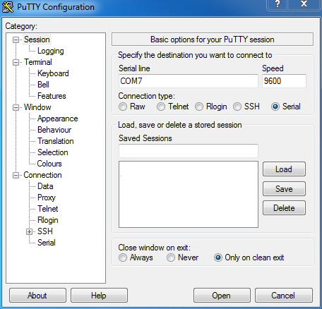
MV Beacon configuration with PuTTY software
In order to open the configuration menu, the user must connect the device to the USB port, wait for the
Virtual COM Port (Virtual COM Port - V-COM) to appear, and connect using a terminal program
specifying the port number. The STATUS LED soldered on the board will blink several times when the
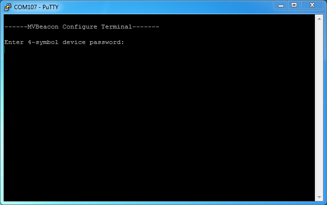
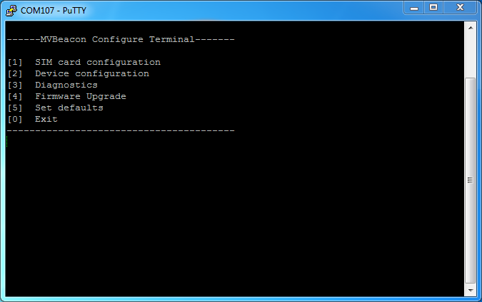
device is powered on, and will be lit when connected to the terminal.When the device connects successfully, a password prompt appears in the terminal window. The user enters a 4-character password (default is "ADMV") without pressing the key; if entered correctly, the main menu (Main screen) appears. Password can be entered incorrectly 4 times. Menu control – number keys. If the configuration is done on a Linux operating system, the requirement may not appear due to different management of USB devices. In this case, you should simply enter the configuration password and the device should connect successfully.
The PuTTY home screen is shown in the image below. You need to choose the right port for connection. In the Microsoft Windows operating system, they are usually named COMx, where x is some integer. On a Linux operating system, the port is usually named /dev/ttyx, where x is an appropriate combination of letters and numbers, for example /dev/ttyACM0.
Enter 4-digit password. Default – ADMV:
Main menu
After entering the correct password, the main menu will appear:
[1]
SIM card configuration
The SIM card configuration menu is selected. User can edit recipient and administrator numbers, PIN code and security settings [2]
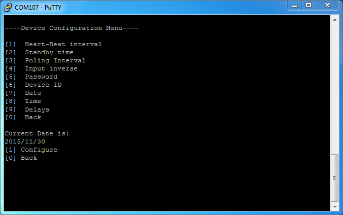
Device configuration
Device configuration menu. User can edit device settings: Device ID, date and time, work and sleep intervals [3]
Diagnostics
Device check (diagnostics) menu. This menu shows the current status of the device. When entering this menu for the first time, it is necessary to wait for the device to register to the network [4]
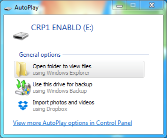
Firmware Upgrade
Confirmation menu for software update. After confirmation, the device goes into update mode and is initialized as a data carrier. To update the device, the user must delete the existing firmware.bin file and upload a new one instead. [5]
Default Settings
Confirmation menu for resetting to default settings. After confirmation, the device loads the default settings, including the device password [0]
Exit
Disconnecting USB mode. It is always recommended to exit before disconnecting the device from the USB port SIM card configuration menu


-
SIM card configure menu
[1]
First Recipient number (P1)
P1 recipient phone number configuration menu. "0" - the number is disabled; otherwise, a valid phone number must be used. This phone number is disabled by default. [2]
Second Recipient number (P2)
P2 recipient phone number configuration menu. "0" - the number is disabled; otherwise, a valid phone number must be used. This phone number is disabled by default. [3]
Admin number
ADM Administrator phone number configuration menu. "0" - the number is disabled; otherwise, a valid phone number must be used. This phone number is disabled by default. This number is required. [4]
PIN number
PIN number configuration menu. If the PIN number is disabled on the SIM card, this setting is ignored. [6]
Security
Security level configuration menu. Security level 0, 1, 2 or 3 can be selected. [7]
Access Point Name (APN)
It is allowed to change the name of the connection point. [8]
Access Point User Name
It is allowed to change the user name of the access point [9]
Access Point Password
It is allowed to change the access point user password [0]
Back
Returns to the main menu. PIN number editing:
1. To configure the PIN number and phone numbers, select "SIM card configuration": in the main menu - press [1];
2. Open the PIN number configuration window (by pressing [4]);
3. Edit PIN number (By pressing [1]);
4. Enter the PIN number, press to save, or to reject;
5. Enter the PIN number again.
Admin number editing:
1. Open the admin number configuration window (by pressing [3]);
2. Edit administrator number (By pressing [1]);
3. If "0" is entered, the number is disabled.
4. Enter the administrator's number, press to save, or to reject;
Device configuration menu
Delays menu
[1]
Transient time limit
This time determines when the short-term error ends and when the long-term error takes effect. Default is "0" - disabled. This time is measured in seconds. [2]
Filter time limit
This time determines how long (in milliseconds) the signal must be for it to be captured. The default is 80 ms. Password editing:
1. Return to the main menu by pressing [0] (Back).
2. Enter the Device configuration menu by pressing [2];
3. To see the password configuration window - press [5];
4. Edit password - (by pressing [1]);
5. Enter the password, press <enter> to save, or <esc> to reject;
6. Enter the password again.
Time editing:
1. Enter the time editing window by pressing [8];
2. Edit time by pressing [1];
3. Enter the hour, press <enter> ;
4. Enter minutes, press <enter>;
5. Enter seconds, press <enter>.
Diagnostics menu
1. Return to main menu by pressing [0];
2. Enter the Diagnostics screen by pressing [3];
3. Wait for the device to register to the network. When connected successfully, the operator name
and signal quality will appear on the screen. If the modem does not connect to the network, the
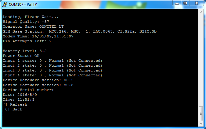
message Modem failed appears on the screen.Diagnostics screen
Signal Quality;
Signal quality; measured in dBm
Operator Name;
Operator name
GSM Base Station;
Data about the connected base station Modem Time
Autocalibration time
Pin Attempts left;
Shows the balance of SIM PIN entry attempts Battery level;
Battery level (in Volts)
Power State
Power status: OK – power is present / battery is not discharging; PWRLOW – if the battery voltage is below 2.7 V (Beacon B+) or if the power is lost and the device is running on internal batteries (Beacon A). Input 1 state; Input 2 state Input 3 state; Input 4 state
Input status, input invert selections and whether it is connected. Device Hardware version
Hardware version
Device Software version
Software version
Date
Device date
Time
Device time
Test result window:

MV Beacon configuration with SMS messages
The first four characters of the SMS message must be the device password. The type of message is
written after the password: SET – configuration setting type; or GET - read configuration type.
Parameters and their values are written after the password and message type. The password,
message type, and [parameter=value;] blocks must be separated by spaces. The [Parameter=value;]
block must contain no spaces, and the end of the block is marked with a semicolon (;)Function
Description
Answer
PASSWORD SET PARAM1=VALUE1; [PARAM2=VALUE2;]...
PASSWORD – 4 symbol password
PARAM1 – Parameter name
PARAM2 – Parameter name
VALUE1 – Parameter value
VALUE2 – Parameter value
SET PARAM=VALUE1; [PARAM=VALUE2;]…
SET ERROR
PASSWORD GET PARAM1; [PARAM2;]...
PASSWORD – 4 symbol password
PARAM – Parameter name
GET PARAM1=VALUE1; [PARAM2=VALUE2;]...
GET ERROR
Function examples:
Description
Request
Answer
Set Recipient and Admin numbers, new password and Heart-beat interval. ABCD SET P1=37060001001; ADM=37060001001; PASS=1234; HB=24;
SET P1=37060001001; ADM=37060001001; PASS=1234; HB=24;
Get battery level, signal quality and hardware version (with new password) 1234 GET BAT GSQ HWV
GET BAT=3,7; GSQ=-50; HWV=1,0;
Set password, Heart-Beat interval and standby time; Heart-beat interval and password do not meet the requirements (password too short, Heart-Beat too long) AAAA SET PASS=K; HB=35600; SB=20;
SET Err PASS=AAAA; Err HB=12; SB=20;
List of functions, initial values and pemissions:
Spontaneous messages
Syntax
Description
Example
1
EVENT TYPE PARAM=VALUE1; [PARAM=VALUE2;]...
TYPE – event type:
-
HB – Heart-beat message
-
PO – login message
-
TG – entry trigger message
-
EVENT PO ID=BECON1; I1=0; I2=0; I3=0; I4=0; GSQ=99dB; BAT=3,2; D=2015.05.21; T=22:23:21;
-
-
EVENT TG ID=BECON1; I1=1; I2=0; I3=0; I4=0; GSQ=50dB; PWRLOW=1; D=2015.05.21; T=22:23:21;
EVENT HB ID=BECON1; GSQ=-50; BAT=1,1; D=2015.05.21; T=22:23:21;
MV Beacon program update using USB port
To update the software, the user must enter the main menu, enter the update confirmation menu by
pressing [4] (Firmware upgrade) and confirm the update [1] (confirm update); The device is now in
update mode.The device disconnects and connects already as a data carrier:
The user must delete the existing firmware.bin file and load the new one by copying.
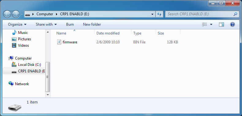
After all the steps are completed, the user needs to unplug the device and reboot it. The name of the
new software version should have changed in the diagnostics menu window.MV Beacon program update via internet
After the user sends the message "GET FIRMWARE" (see the configuration message tables), the
device connects to the FTP server, downloads the firmware and sends an SMS message with a
response whether the download was successful. The device then overwrites the downloaded firmware
and sends an "EVENT PO" message. The software version can be checked by sending the message
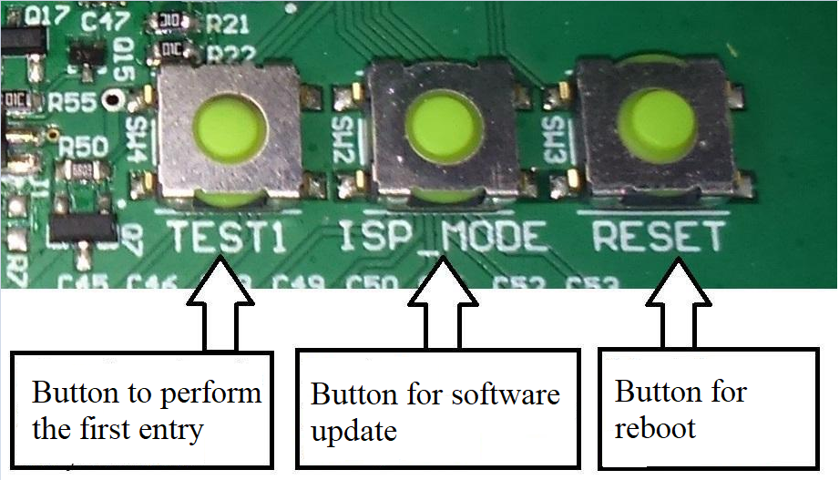
"GET SWV".Testing
When the user has finished configuring the device and the Diagnostics menu shows a successful
network connection, the user can test the device by pressing and holding the TEST1 button for a few
seconds. The user should then receive a TG type SMS message with the changed value of the
pressed input. When the button is released, a second SMS message is received.
-