IOMOD HT User Manual Modbus
Introduction
IOMOD HT is used for temperature and humidity data monitoring over Modbus (RTU), IEC 60870-5-103 or IEC 60870-5-101. The advanced version of the device is also capable of switching relays automatically (thermostat function) as configured.
Features
- Temperature measurement in 0.1°C resolution
- Humidity measurement in 0.1% resolution
- Modbus, IEC-60870-5-103 and IEC-60870-5-101 communication over RS485
- 2 normally open relay outputs (advanced version)
- Automatically configurable relay switching on temperature or humidity change
- Configuration over USB console
- Drag and Drop firmware upgrade over USB mass storage
- LED indication for input/output and data transmission
- Spring contact connectors
- Easy connection with WCC Lite gateway and CloudIndustries.eu platform
Operational Information
IOMOD uses Modbus (RTU) or IEC-60870-103 or IEC-60870-101 protocols over RS485 connection, which can be used with cable length up to 1500 meters and connect up to 30 devices on one line. Default Modbus settings are: 9600 baudrate, 8 databits, N parity, 1 stopbit , Slave address - 1.
To read temperature and humidity, user can use device with default settings without configuring it. To read humidity, send 04 Modbus command (Read Input Registers) with resolution of first register (0). Returned value will be measured in % and will be multiplied by 10, to show one decimal place. To read temperature, send 04 (Read Input Registers) with resolution of second register (1). The returned value will be measured in °C and will be multiplied by 10.
PWR LED
Green - Normal operation, device is powered correctly.
RX/TX LED
The RX/TX LED on the IOMod flashes when data is either being transmitted or received via the RS485 port.
IOMod HT advanced temperature and humidity limit operation logic
First Relay (Heater):
- Activation Conditions: When temperature drops below lower limit OR humidity exceeds upper limit.
- Deactivation Conditions: When temperature rises by 5 degrees above the set temperature limit.
This logic ensures that the heater is activated when the conditions are too cold (temperature drops below the lower limit) or too humid, and it's deactivated when the temperature rises sufficiently.
Second Relay (Fan):
- Activation Conditions: When temperature or humidity exceeds the upper limit.
- Deactivation Conditions: When humidity decreases by 10% AND temperature gets below the set temperature limit by 5 degrees.
This logic ensures that the fan is activated when conditions are too hot or humid, and it's deactivated when both humidity decreases sufficiently and temperature decreases to a set level.
To enable thermostat function, user can configure device over USB or over MODBUS. Configurable options are shown in table below.
| CONFIGURABLE OPTIONS | OVER USB | OVER MODBUS |
| Slave Address | Yes | No |
| Baudrate | Yes | No |
| Data, Stop and Parity bits | Yes | No |
| RS485 Terminating Resistor | Yes | No |
| 1st Relay enabled/disabled | Yes | Yes |
| 1st Relay set temperature and humidity limit | Yes | Yes |
| 2nd Relay enabled/disabled | Yes | Yes |
| 2nd Relay set temperature and humidity limit | Yes | Yes |
| Default Settings | Yes | No |
Supported MODBUS functions
IOMod HT basic
04 (0x04) Read Input Registers
Reads current Humidity and Temperature status. Address 0 – Humidity, Address 1 – Temperature; Value is multiplied by 10 to show one decimal place. For example: 23.3 °C will be shown as 233; 50.0 % will be shown as 500 in the Registers.
IOMod HT Advanced
01 (0x01) Read Coils Status
Reads the status of relays (True - closed or False - open). IOMOD HT advanced has 2 relays on coils #6 (heater) and #7 (fan).
03 (0x03) Read Holding Registers
Reads current configuration of relays. Address 2 – Relay #1 (heater) control: 0- disabled; 1 - enabled; Address 3 – Relay #1 (heater) temperature lower limit value; Address 4 - Relay #1 (heater) humidity upper limit value; Address 5 – Relay #2 (fan) control: 0- disabled; 1 - enabled; Address 6 – Relay #2 (fan) temperature upper limit value; Address 7 – Relay #2 (fan) humidity upper limit value;
04 (0x04) Read Input Registers
Reads current Humidity and Temperature status. Address 0 – Humidity, Address 1 – Temperature; Value is multiplied by 10 to show one decimal place. For example: 23.3 °C will be shown as 233; 50.0 % will be shown as 500 in the Registers.
06 (0x06) Preset Single Register
Sets single relay configuration. Address 2 – Sets Relay #1 (heater) On or Off: 0- disabled; 1 - enabled; Address 3 – set Relay #1 (heater) temperature lower limit; valid range -10 to 60; Address 4 - set Relay #1 (heater) humidity upper limit: valid range 0-100; Address 5 – Set Relay #2 (fan) On or Off: 0- disabled; 1 - enabled; Address 6 – set Relay #2 (fan) temperature upper limit; valid range -10 to 60; Address 7 – set Relay #2 (fan) humidity upper limit; valid range 0-100.
Technical information
| System | ||
| Dimensions | 26 (H) x 71 (W) x 71 (L), mm | |
| Case | ABS, white | |
| Working environment | Indoors | |
| Working temperature | -20 ÷ +70 °C | |
| Recommended operating conditions |
5 – 60 °C and 20 – 80 %RH; | |
| Configuration | USB | |
| Firmware upgrade | USB – mass storage device | |
| Electrical Characteristics | Basic | Advanced |
| Termination Resistor | Selectable 120 Ω | Selectable 120 Ω |
| Power supply | 12-24 VDC, 8 mA (nominal); 5-33 VDC (full range) | 24 VDC, 25 mA (nominal); 18-27 VDC (full range) |
| Relays | - | 2 (Normally Open); |
| Relay specifications | Basic | Advanced |
| Resistive load (cosφ=1) | - | 5 A at 250 VAC, 5 A at 30 VDC |
| Inductive load (cosφ=0.4, L/R=7ms) | - | 2 A at 250 VAC, 2 A at 30 VDC |
| Max. switching power | - | 1,250 VA, 150 W |
Device Connection
IOMOD HT has an integrated 120 Ω termination resistor which can be enabled or disabled over USB configuration. It is recommended to use termination at each end of the RS485 cable. See the typical connection diagram on Fig. 1.
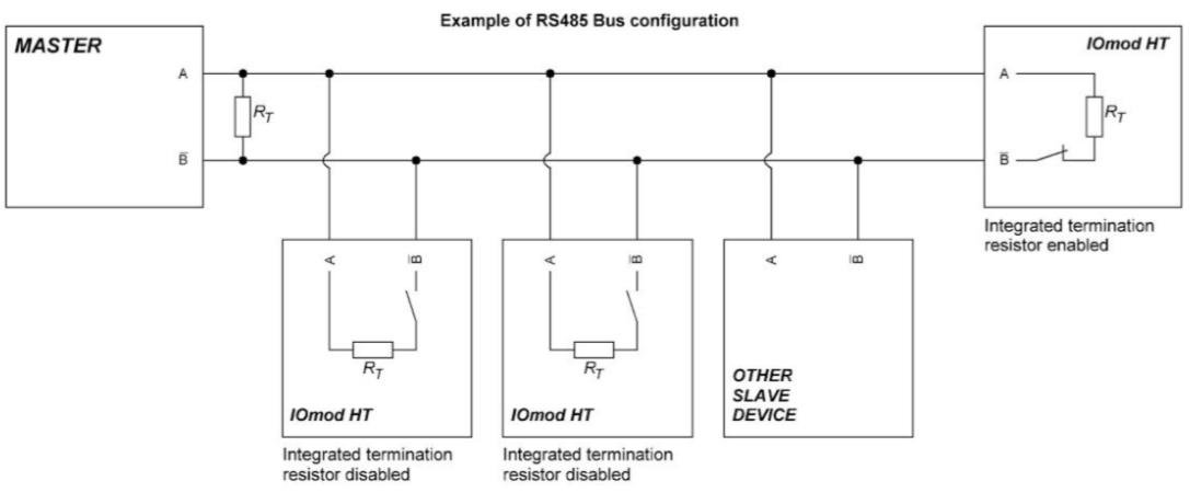
Fig. 1.
Figure 2 shows explanation on device connection.
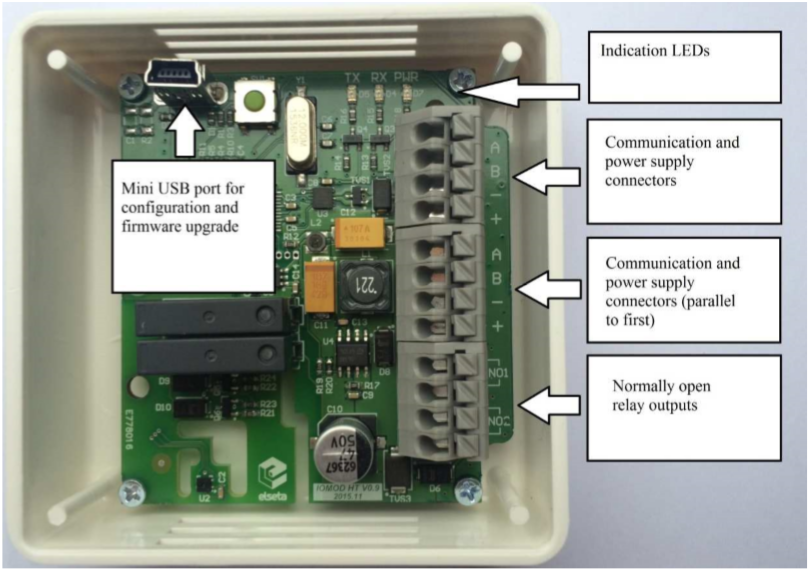 Fig. 2.
Configuration over USB
Driver installation
Device requires USB drivers to work as a Virtual COM port. First-time connection between device and computer could result in “Device driver software was not successfully installed” error such as one shown in Fig. 3.
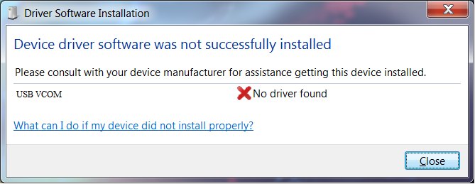
Fig. 3.
A user then should manually install drivers by selecting a downloaded driver folder:
- Go to Control Panel -> Device Manager;
- Select a failing device;
- Press “Update driver software”; screen as in Fig. 4 should appear:
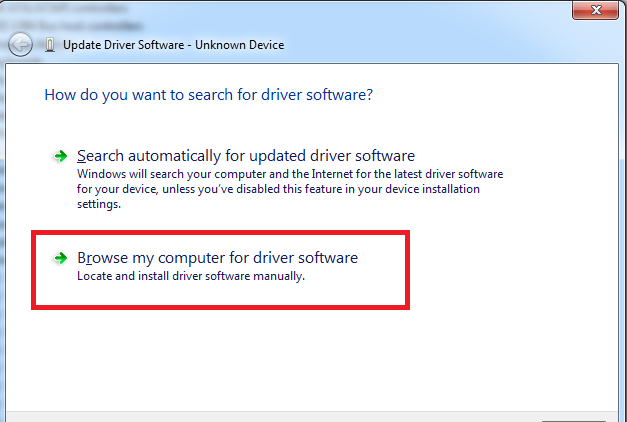
Fig. 4.
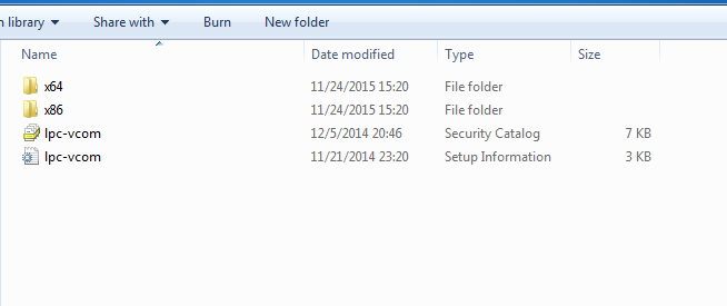
- Select “x86” driver for a 32-bit machine or x64 for a 64-bit machine. If not sure, select a root
folder (folder in which x64 and x86 lay inside, as in Fig. 5).
IOMod HT configuration via PuTTY terminal
Configuration of IOMOD device is done through CLI (Command Line Interface) on virtual COM port. Drivers needed for MS Windows to install VCOM will be provided. To open up CLI simply connect to specific VCOM port with terminal software (it is advised to use PuTTY terminal software. If other software is being used, user might need to send <return> symbol after each command). When connected user should immediately see main screen similar to one in Fig. 6.
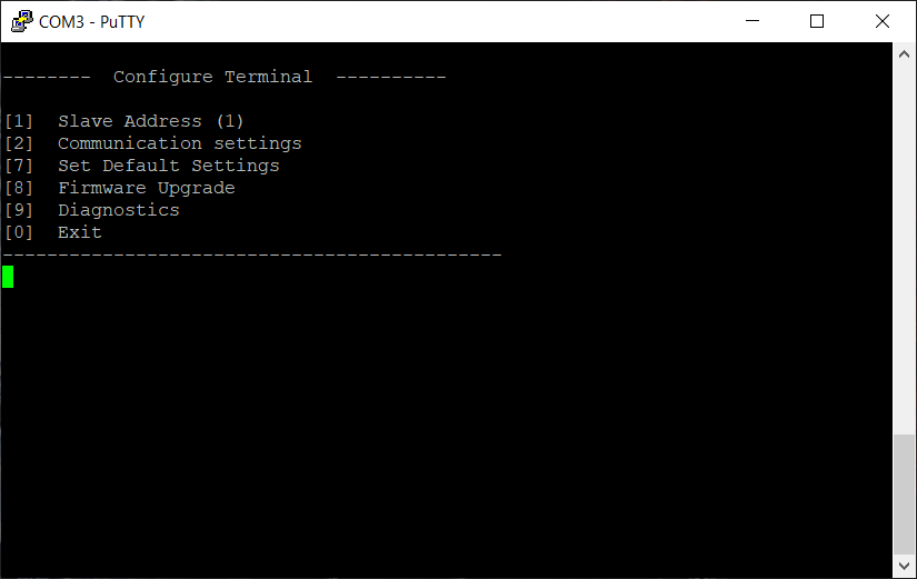 Fig. 6.
If terminal window is accidentally closed without exiting, user can connect to terminal again, and press any key on keyboard to show up main menu once again.
Configuration of device is not possible when USB Simulation Mode is entered. To access configuration menu again user should reset device and then try again.
|
Menu Name |
Function |
Values |
Default Values |
|
| 1. |
Slave Address |
Modbus Slave address / ID |
1-254 |
1 |
| 2. |
Communication settings |
[1] Baud rate, [2] Data, Stop and Parity Bits, [3] RS485 Terminating resistor |
[1] 100 - 256000, [2] 8 Data bits + 1/2 Stop bits, Even/None/Odd Parity [3] Enabled/Disabled |
[1] 9600, [2] 8+1 None, [3] Disabled |
| 7. |
Set Default Settings |
Sets Default Settings |
[1] Confirm |
- |
| 8. |
Firmware Upgrade |
Mass Storage Device Firmware Upgrade |
[1] Confirm |
- |
| 9. |
Diagnostics |
Monitoring values |
[] Refresh, |
- |
| 0. |
Exit |
Exit and disconnect |
- |
- |
IOMOD HT Advanced modbus main menu
| Main Menu | Function | Values | Default Values | |
| 1. | Slave Address | Modbus Slave address / ID | 1-247 | 1 |
| 2. | Communication settings |
[1] Configure baudrate [2] Data, stop and Parity bits [3] RS485 Terminating Resistor |
[1] 100 - 256000 [2] 8 Data bits + 1/2 Stop bits, Even/None/Odd Parity [3] Enabled/Disabled |
[1] 9600 [2] 8+1 None [3] Disabled |
| 3. | Relay #1 (heater) settings |
Active mode and active range [1] Enable/disable relay [2] Set temperature limit [3] Set humidity limit |
[1] disable [1], enable [2] [2] Valid range -10 to 60 °C [3] Valid range 0 to 100 % |
[1] Disabled [2] 0 °C [3] 0 % |
| 4. | Relay #2 (fan) settings | Active mode and active range
[1] Enable/disable relay [2] Set temperature limit [3] Set humidity limit |
[1] disable [1], enable [2] [2] Valid range -10 to 60 °C [3] Valid range 0 to 100 % |
[1] Disabled [2] 0 °C [3] 0 % |
| 7. | Set Default Settings | Sets Default Settings | [1] Confirm [0] Cancel |
- |
| 8. | Firmware Upgrade | Mass Storage Device Firmware Upgrade | [1] Confirm [0] Cancel |
- |
| 9. |
Diagnostics |
Monitoring values |
[] Refresh, |
- |
| 0. | Exit | Exit and disconnect | - | - |
Firmware upgrade over USB
To update device firmware user must enter main configuration menu.
Enter Firmware update screen by pressing [8];
Confirm update by pressing [1];
User then must delete existing file “firmware.bin”, and simply upload new firmware file by drag and drop, Fig. 7.
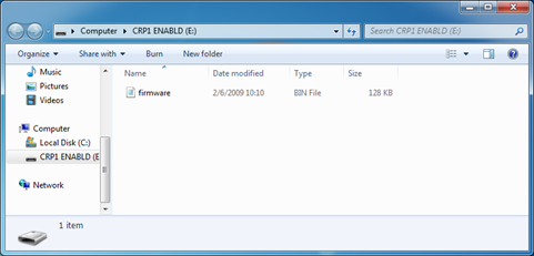 Fig. 7.
Reconnect device and check firmware version. It should now represent the one it was updated to.
Testing With “THE VINCI” software
To test IOMOD HT with default settings, user can connect device through RS485 to Modbus or IEC-60870 (depending on firmware) master or using USB Simulation Mode. Example will show The Vinci Expert as serial interface converter and adapter to PC with The Vinci software. Default settings – 9600 baud; 8 databits, none parity, 1 stop bit. When opening The Vinci software, choose Modbus serial – Master mode. In Settings tab, choose Slave address (default – 1); configure a job as shown in Figure 8 and set the tag names to the created job if needed; the presented values are multiplied by 10 as mentioned before. Press Start and go to the Statistic tab.
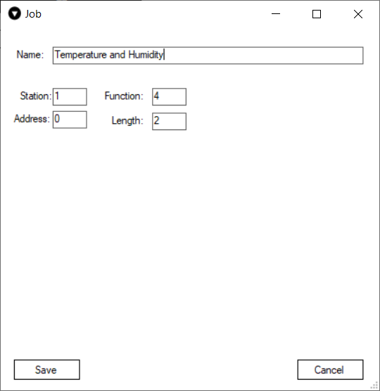 Fig. 8.
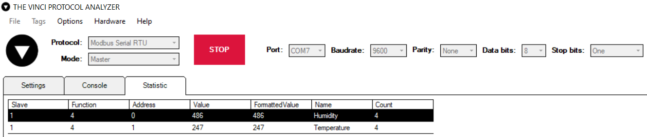 Fig. 9. Basic version example
Downloads
Configuration example download for IOMod HT basic -> iomod_HT_Modbus_to_IEC104_SCADA.xlsx
Configuration example download for IOMod HT advanced -> iomod_HT_advanced_Modbus_to_IEC104_SCADA.xlsx
IOMOD HT Modbus firmware ->IOMOD_MODBUS_v1_24_4.bin