IOMOD FPI User Manual
1. Introduction
IOMod FPI stands for Fault Passage Indicator. It is an intelligent electronic device (IED) used for short circuit and ground fault indication with direction detection. It measures three phases of AC voltage and current amplitudes and phase shifts. The faults are detected by applying certain algorithms along with the measured data. The measured and calculated values are transmitted to the host system via communication protocol Modbus RTU, IEC 60870-5-101 or IEC 60870-5-103.
1.1 Features
- Directional fault detection for all network types;
- Earth fault detection;
- 50 Instantaneous overcurrent detection;
- 50N Neutral instantaneous overcurrent detection;
- 51/67 Phase directional overcurrent detection;
- 67N Neutral directional overcurrent detection;
- 27 Undervoltage detection (with VT or voltage sensors);
- 59 Overvoltage detection (with VT or voltage sensors);
- 59N Neutral overvoltage detection / permanent earth fault (with VT or voltage sensors);
- 81HBL2 Inrush blocking for selected protections;
- 2 settings groups;
- Integration into Elseta mini RTU;
- Measurements of RMS values for currents, phase, and phase-to-phase voltages.
- Additional measurements of:
- Frequency;
- Active, reactive, and apparent power;
- Neutral voltage, neutral current;
- Power factor;
- Phase angle;
- Analog inputs measurement in 16-bit resolution;
- 3x low-power (LoPo) current measuring inputs (225 mV) or 3 x 1 A/5 A CT with the adapter;
- 3x low-power (LoPo) voltage measuring inputs (3.25 V/√3) or 3 x 100 V/400 V VT with the adapter;
- Frequency acquisition (Nominal frequencies: 50 and 60 Hz; Frequency range: 45–65 Hz);
- Firmware upgrade over USB, RS485;
- Configurable using the IOMOD Utility app for user-friendly setup;
- RS485 interface with a switchable terminating resistor;
- Compact case with a removable transparent front panel;
- DIN rail mounting for seamless integration into industrial systems.
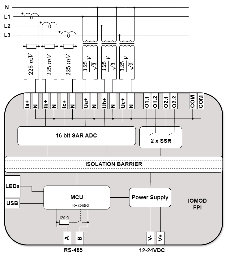
1.2 Block diagram
Fig. 1.2.1 IOMOD FPI internal structure and block diagram
2. Hardware data
2.1 Mechanical drawings
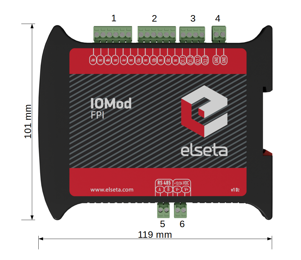
Fig. 2.1.1 IOMod FPI side view with dimensions and terminals description. 1 - first channel three phase
current inputs; 2 - three phase voltage (second channel current) inputs; 3 - four digital outputs;
4 - ground input for analogue measurements; 5 - RS485 interface; 6 - power supply input
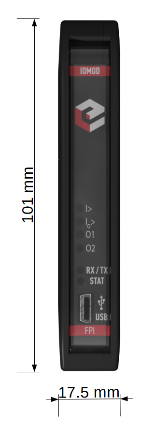
Fig. 2.1.2 IOMod FPI front view with dimensions
2.2 Terminal connections
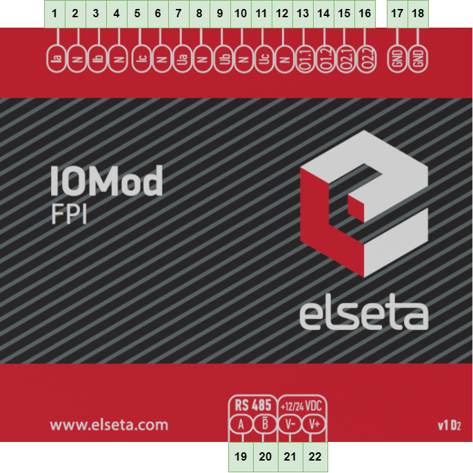
IOMod FPI has 22 terminals, which are depicted below:
Fig. 2.2.1 IOMod FPI terminal diagram
The description of each terminal can be found in the table below:
Table 2.2.1 Terminal Specifications
|
Terminal number |
Terminal name |
Description |
|---|---|---|
|
1 |
Ia | Phase current 1 |
|
2 |
N | |
|
3 |
Ib | Phase current 2 or neutral current in case of I0 metered mode |
|
4 |
N | |
|
5 |
Ic | Phase current 3 |
|
6 |
N | |
|
7 |
Ua | Phase voltage 1 or phase current 1 in case of 3I3I connection mode |
|
8 |
N | |
|
9 |
Ub | Phase voltage 2 or phase current 2 in case of 3I3I connection mode, or neutral current in case of 3I3I connection mode along with I0 metered mode |
|
10 |
N | |
|
11 |
Uc | Phase voltage 3 or phase current 3 in case of 3I3I connection mode |
|
12 |
N | |
|
13 |
O1.1 | Digital output 1 |
|
14 |
O1.2 | |
|
15 |
O2.1 | Digital output 2 |
|
16 |
O2.2 | |
|
17 |
COM | Analogue measurements common neurtal terminals |
|
18 |
COM | |
|
19 |
A | RS485 interface port |
|
20 |
B̄ | |
|
21 |
V- | Power source inputs |
|
22 |
V+ |
2.3 Status indication
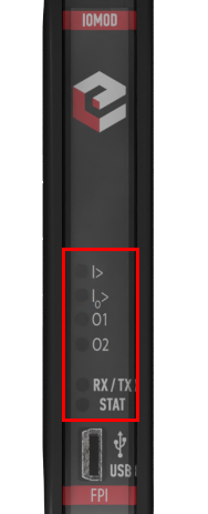
IOMod FPI has six LEDs (Fig 2.3.1), which are used to indicate the fault detection, communication and power statuses.
Fig. 2.3.1 IOMod FPI LEDs physical location
The description of each IOMod FPI LED can be found in the table below:
Table 2.3.1 Description of LEDs.
|
Name |
LED color |
Description |
|---|---|---|
|
I> |
🟢 (green) |
The current level of all channel inputs is acceptable |
|
🔴 (red) |
Overcurrent is detected in one or more current lines. The LED indication is active only if one of the current fault detection functions (50, 51, 67) is activated |
|
|
I0> |
🟢 (green) |
The neutral current level is acceptable. |
|
🔴 (red) |
Neutral current line earth fault is detected in either A or B direction. The LED indication is active only if one of the neutral current fault detection functions (50N, 51N, 67N) is activated. |
|
|
O1 |
🟢 (green) |
Digital output is tripped. |
|
🔴 (red) |
Digital output is closed. The output closing can be triggered by:
|
|
|
O2 |
🟢 (green) |
Digital output is tripped. |
|
🔴 (red) |
Digital output is closed. The output closing can be triggered by:
|
|
|
RX/TX |
🟢 (green) |
Blinking green light indicates active communication via RS485 interface. |
|
STAT |
🟢 (green) |
Power source is connected to the power supply input. |
|
🔵 (blue) |
IOMod FPI is connected to an external device via USB mini cable. |
3. Technical information
Table 3.1 Technical specifications.
| System | ||
| Dimension | 17.5 (H) x 101 (W) x 119 (L), mm | |
| Case | ABS, black |
|
| Working environment | Indoor |
|
| Operating temperature | -40°C ... +85°C |
|
| Recommended operating conditions | 5–60°C and 20–80% RH |
|
| Configuration |
USB, RS485 |
|
| Firmware upgrade | USB, RS485 |
|
| Electrical specifications |
||
|
Inputs |
Resolution |
16 bits |
|
Input resistance |
~1 MΩ |
|
|
Input capacitance |
< 170 pF |
|
|
Input ranges |
±10 V (amplitude) |
|
|
Nominal values |
Current input: 225 mV (RMS) Voltage input: 1.876 V (RMS) |
|
|
Overvoltage protection for all inputs |
up to ±20 V |
|
| Outputs | On-Resistance (max) |
16 Ω |
| Power |
||
| Power Supply | 9–33 VDC (full range) |
|
| Current consumption | 40 mA @ 12 VDC, 20 mA @ 24 VDC |
|
4. Mounting and installation
4.1 Connection Diagrams
In this chapter the various options of connecting the device to medium-voltage systems are discussed.
4.1.1 3 Low-Power Current Sensor, 3 Low-Power Voltage Sensors
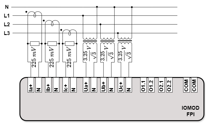
In the case of 3I3U connection mode IOMod FPI can be connected to a medium-voltage system by using low-power current and low-power voltage sensors (Fig. 4.1.1.1). In this scenario the neutral current I0 and the neutral voltage U0 are calculated by taking a vector sum of appropriate measurements. IOMod FPI GND inputs are not required to be connected to the neutral line because they are interconnected with signal neutral inputs (Fig. 1.2.1). As far as voltage measurements are taken along with current measurements directional information can be provided in case of a fault.
Fig. 4.1.1.1 Connection diagram with 3 low-power current and 3 low-power voltage sensors
4.1.2 Fault Passage Indicator for a single feeder
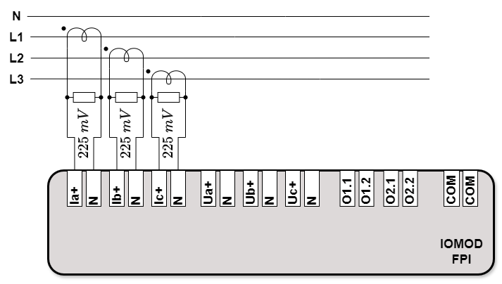
IOMod FPI can perform fault passage indication with only its current inputs connected to a single feeder of a medium-voltage system (Fig. 4.1.2.1). In the scheme below IOMod FPI current inputs are connected to a feeder via low-power current sensors. However, this connection scheme restricts IOMod FPI fault detection capabilities only to the current related faults. Also, the absence of voltage measurements results in inability to provide the directional fault information.
Fig. 4.1.2.1 IOMod FPI connection diagram for a single feeder
4.1.3 Fault Passage Indicator for two feeders
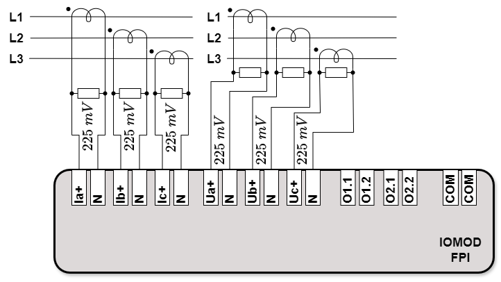
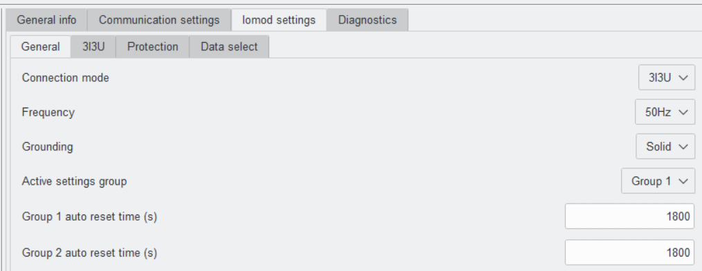
The special feature of IOMod FPI is the ability to be used as a fault passage indicator for two feeders (Fig 4.1.3.1). In this case 3I3I connection mode needs to be enabled in IOMod Utility (Fig. 4.1.3.2).
Fig. 4.1.3.1 IOMod FPI connection diagram for two feeders
Fig. 4.1.3.2 IOMod Utility General settings tab with Connection mode set to 3I3I
This mode allows us to use IOMod FPI voltage inputs for current measurements, so that the currents of both feeders are measured simultaneously. In the connection scheme above (Fig. 4.1.3.1) IOMod FPI current inputs are connected to the pair of feeders via low-power current sensors. Similarly to the previous example, the absence of voltage measurements results in inability to provide the directional fault information. Besides, this connection scheme restricts IOMod FPI fault detection capabilities only to the current related faults.
4.1.4 3 Low-Power Voltage Sensor, 2 Phase Current, and Core Balance Current Transformer
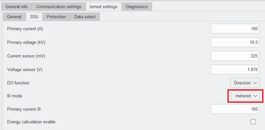
IOMod FPI allows directly measure the neutral current. In order to use this feature I0 current acquiring mode needs to be switched in IOMod Utility from calculated to metered (Fig. 4.1.4.1).
Fig. 4.1.4.1 IOMod Utility 3I3U settings view with I0 mode switched to metered
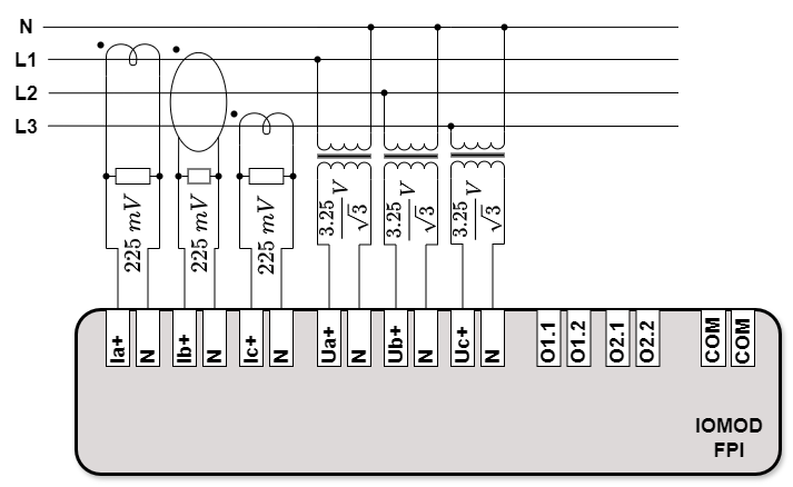
After enabling I0 metered mode IOMod FPI second phase input (Ib+/N) becomes neutral current input. Since neutral current measurements are performed directly instead of being calculated it allows to achieve much higher precision and sensitivity. While neutral current being metered directly, the second phase measurements are being calculated by taking a vector sum of the measured currents. In the scheme below (Fig. 4.1.4.2) current and voltage measurements are taken by using low-power current and low-power voltage sensors. The second input (Ib+/N) is connected to a low-power current sensor which is placed on the neutral line.
Fig. 4.1.4.2 IOMod FPI I0 metered mode connection diagram
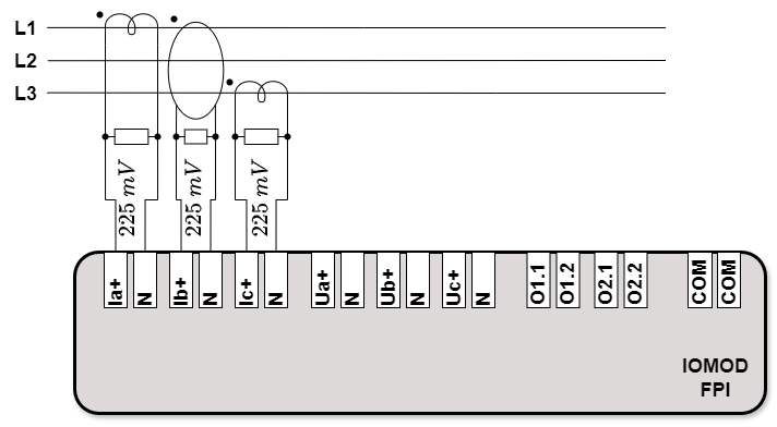
4.1.5 2 Phase Current, and Core Balance Current Transformer
Similarly to I0 calculated mode IOMod FPI can take solely current measurements via low-power current sensors (Fig. 4.1.5.1). However, this connection scheme restricts IOMod FPI fault detection capabilities only to the current related faults. Also, the absence of voltage measurements results in inability to provide the directional fault information.
Fig. 4.1.5.1 IOMod FPI I0 metered mode connection diagram without voltage measurements
4.1.6 2 Phase Current, and Core Balance Current Transformer for two feeders
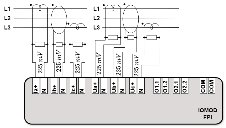
IOMod FPI operating in I0 metered mode preserves the ability of monitoring the currents of two feeders (Fig. 4.1.6.1). In this case 3I3I connection mode needs to be enabled in IOMod Utility (Fig. 4.1.3.2). 3I3I connection mode allows using voltage inputs as second channel current inputs.
Fig. 4.1.6.1 IOMod FPI connection diagram for two feeders
with both channels I0 metered mode
In the connection scheme above (Fig. 4.1.6.1) IOMod FPI current inputs are connected to the pair of feeders via low-power current sensors. It should be noted that the absence of voltage measurements results in an inability to provide the directional fault information. Besides, this connection scheme restricts IOMod FPI fault detection capabilities only to the current related faults.
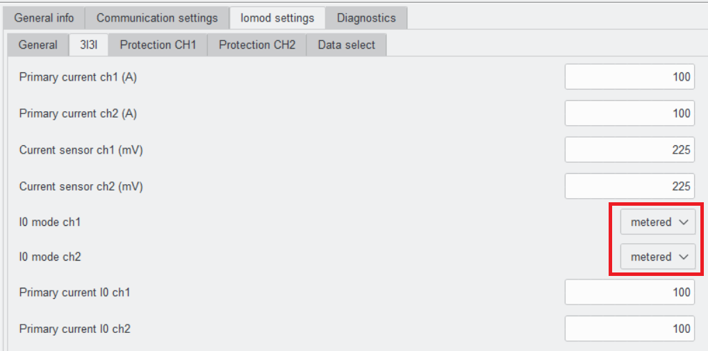
Moreover, in IOMod Utility I0 mode of both current input channels needs to be changed from calculated to metered (Fig. 4.1.6.2).
Fig. 4.1.6.2 IOMod Utility 3I3I settings view with I0 mode of both channels set to metered
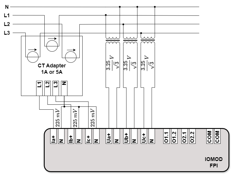
4.1.7 Conventional Current transformers (CT) connection via CT adapters.
IOMod FPI can take current measurements via a current transformer adapter (Fig. 4.1.7.1). Contrary to the current sensors, current transformers are usually intended for transforming priorly lowered currents from secondary distribution networks.
Fig. 4.1.7.1 IOMod FPI connection diagram with current transformer adapter
and low-power voltage sensors
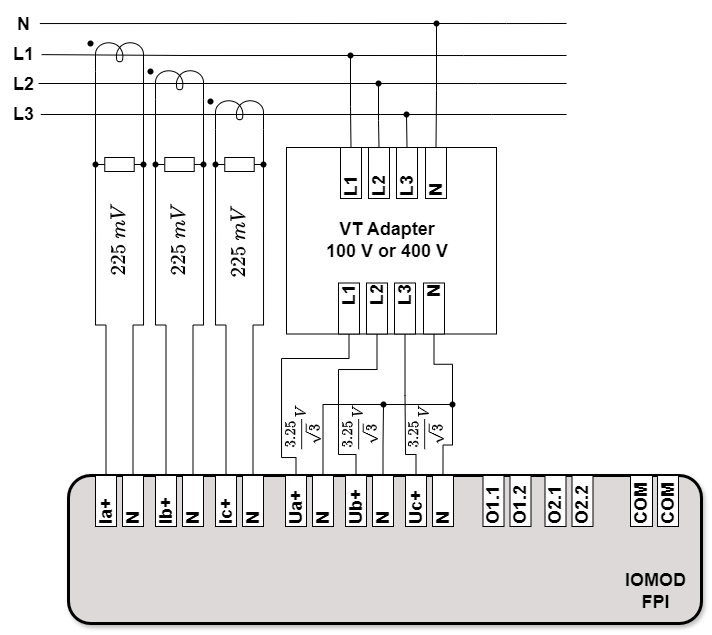
4.1.8 Conventional Voltage transformers (VT) connection via VT adapters.
IOMod FPI is able to take voltage measurements via a voltage transformer adapter (Fig. 4.1.7.1). Contrary to the voltage sensors, voltage transformers are usually intended for transforming priorly lowered voltages from secondary distribution networks.
Fig. 4.1.8.1 IOMod FPI connection diagram with low-power current sensors
and voltage transformer adapter
4.2 Digital outputs
IOMod FPI has two digital outputs which are based on Solid State Relays (SSR). Since SSR's are in use an additional up to 16 Ω on-resistance is introduced. Operation logic of digital outputs is predetermined and cannot be controlled or configured via IOMod Utility. The operation of a digital output is triggered when a certain fault is detected (Table 4.2.1). The statuses of both digital outputs are indicated by two LED's (Table 2.3.1).
Table 4.2.1 Digital outputs activation conditions.
|
Output Number |
Activation Conditions |
|---|---|
|
1 |
Over current in the first channel (in case of 50 and 51 detection functions) |
|
Over current in A direction (in case of function 67) |
|
|
2 |
Over current in the second channel (in case of 50 and 51 detection functions and 3I3I connection mode) |
|
Over current in B direction (in case of function 67) |
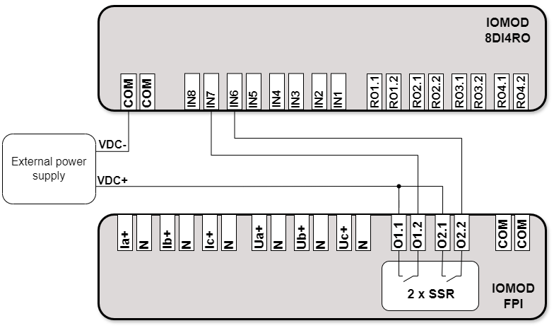
In the scheme below an application example of IOMod FPI digital outputs with another device is displayed (Fig. 4.2.1). For the sake of the example IOMod 8DI4RO was selected as a device for receiving digital signals from IOMod FPI. The first terminal of both digital outputs O1.1 and O2.1 are connected to a common external voltage source. The second terminal of the first digital output O1.2 is connected to IOMod 8DI4RO seventh digital input IN7. The second terminal of the second digital output O2.2 is connected to IOMod 8DI4RO sixth digital input IN6. The negative terminal of the voltage source is connected to IOMod 8DI4RO input ground terminal. The digital output is activated when one of the relays becomes closed. It closes the previously described circuit as well.
Fig. 4.2.1 Digital outputs usage block diagram example with IOMod 8DI4RO
4.3 RS485 Interface
IOMod 4Cs4Vs has an integrated 120 Ω termination resistor, which can be enabled or disabled via the configuration terminal. It is recommended to use termination at each end of the RS485 cable.
IOMod FPI has a 1/8 Unit load receiver which allows having up to 255 units on a single line (compared to the standard 32 units). To reduce reflections, keep the stubs (cable distance from the main RS485 bus line) as short as possible.
4.4 Power supply
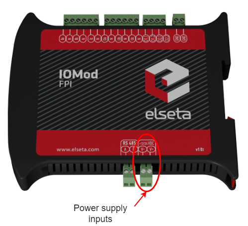
IOMod FPI needs to be powered by a 9–33 V power source. IOMod FPI power supply inputs are located next to RS485 interface inputs (Fig 4.4.1).
Fig. 4.4.1 Power supply inputs physical location
4.5 USB connection
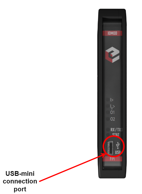
IOMod FPI device has USB-mini connection port. Its primary function is physical connection establishment between the IOMod and a PC. By selecting USB interface and correct communication port in IOMod Utility (Fig. 4.5.1) a user can connect to the IOMod to control its parameters and monitor its measured data and the status of fault detection functions. Also, this connection can be used for powering the module.
Fig. 4.5.1 IOMod Utility interface and communication port parameters
Fig. 4.5.2 IOMod FPI USB connection port physical location
5. Parametrization
In this section IOMod FPI settings configuration is described. IOMod FPI configuration is performed via IOMod Utility (the manual can be accessed here). All IOMod-related settings can be found in "IOMod settings" tab (Fig. 5.1).
Fig. 5.1 IOMod settings tab
5.1 General parameters
In order to configure IOMod FPI general settings open "IOMod settings" tab in IOMod Utility. After clicking on "IOMod settings", "General" section opens (Fig. 5.1.1).
Fig. 5.1.1 IOMod Utility with IOMod FPI general settings window opened
The general settings consist of six parameters, which apply for all communication protocols (Table 5.1.1). "Measurands set" and "Scale factor" are defined only in the context of IEC 60870-5-103 communication protocol. The last parameter "Value update time (ms)" is defined only in the context of IEC 60870-5-101 and IEC 60870-5-103 communication protocols.
Table 5.1.1 IOMod FPI general parameter ranges and default values.
|
Parameter |
Range |
Default value |
|---|---|---|
| Connection mode | 3I3U, 3I3I | 3I3U |
| Frequency | 50 Hz, 60 Hz | 50 Hz |
| Grounding |
Solid, Isolated, Resonant |
Solid |
| Active settings group | Group 1, Group 2 | Group 1 |
| Group 1 auto reset time (s) | 1–60000 | 1800 |
| Group 2 auto reset time (s) | 1–60000 | 1800 |
| Measurands set* | 1–4 or 1–3** | 1 |
| Scale factor* | 1.2, 2.4 | 1.2 |
| Value update time (ms)*** | 20–60000 | 500 |
* The parameters are defined only for IEC 60870-5-103 communication protocol.
** In 3I3I connection mode only first three (1–3) measurands sets are available.
*** The parameter is defined only for IEC 60870-5-101 and IEC 60870-5-103 communication protocols.
The first parameter is "Connection mode" allows to define how the values measured with voltage inputs (terminals 7–12, see Fig. 2.2.1) are supposed to be interpreted. The values are interpreted as voltage measurements by default. This connection mode is denoted by 3I3U designation. 3I3U designation basically means – "three currents and three voltages" meaning that both current and voltage measurements are being taken from a feeder (see Fig. 4.1.1.1 as an example). 3I3U connection mode parameters can be found in a separate settings section which is labeled with communication mode designation (connection mode settings are described in the next section).
Fig. 5.1.2 IOMod Utility IOMod settings sections in 3I3I connection mode
Selecting 3I3I connection mode in IOMod Utility changes IOMod Setting sections (Fig. 5.1.2) – 3I3U changes to 3I3I and Protection section divides into two sections for each channel. IOMod FPI, in 3I3I connection mode, interprets the values measured with voltage inputs (terminals 7–12, see Fig. 2.2.1) as current measurements. 3I3I designation basically means – "three currents and three currents" meaning that the voltage inputs become the second channel current inputs (see Fig. 4.1.3.1 as an example). 3I3I settings section allows us to modify connection mode parameters (described in the next section). Protection CH1 and Protection CH2 store the fault detection function parameters of the first and second current channel respectively.
"Frequency" parameter allows us to set the nominal frequency of the power line to which IOMod FPI is connected to.
"Grounding" parameter sets one of the high-voltage earthing types. The selected earthing type influences the way a fault direction is determined. Also, earthing type effects phase angle calculation.
"Active settings group" allows us to select between two fault detection configuration groups. Two groups allow us to save in IOMod FPI two separate fault detection configurations. The group division can be found in the related to Protection configuration setting sections (Fig. 5.1.3).
Fig. 5.1.3 IOMod Utility Protection function configuration group division
"Group 1 auto reset time (s)" and "Group 2 auto reset time (s)" parameters for each group respectively defines the time after which fault detection statuses are going to be reset automatically. The time period has to be provided in seconds.
If IEC 60870-5-103 communication protocol is selected, "Measurands set" parameter sets one of the lists of measurements (Table 7.3.2, Table 7.3.3) which is going to be sent to a master device.
If IEC 60870-5-103 communication protocol is selected, the "Scale factor" parameter sets a value by which all measurements are going to be multiplied.
Value update time (ms) parameter defines how frequently the updated values are going to be sent to a controlling station via IEC 60870-5-101 or IEC 60870-5-103 communication protocols.
5.2 Connection mode settings
As was described early IOMod FPI supprots two connection modes – 3I3U and 3I3I. After selecting one of them in General settings (Fig. 5.1.1) a new respectively named section appears (Fig. 5.1.1, Fig.5.1.2). In this subsection the parameters of a certain connection mode are going to be described.
5.2.1 3I3U connection mode parameters
3I3U connection mode parameters section has eight parameters (Table 5.2), which are going to be described below.
Table 5.2 3I3U connection mode parameters.
|
Parameter |
Range |
Default value |
|---|---|---|
| Primary current (A) | 1–2000 | 100 |
| Primary voltage (kV) | 0.2–60.0 | 10.0 |
| Current sensor (mV) | 100–300 | 225 |
| Voltage sensor (V) | 1.0–3.0 | 1.876 |
| DO function | Direction, Fault type | Direction |
| I0 mode | Calculated, Metered | Calculated |
| Primary current I0 | 1–2000 | 100 |
| Energy calculation enable | Enabled / Disabled | Disabled |
- The "Primary current (A)" parameter defines the nominal input current of a current sensor or a current transformer.
- The "Primary voltage (kV)" parameter sets the nominal input line voltage of a voltage sensor or a voltage transformer. If instead of the line voltage, the sensor or adapter converts the phase voltage, still the value of the line voltage must to be used. For example, if a voltage sensor declares the primary voltage of 10/√3 kV, then 10 kV must be used for "Primary voltage (kV)" parameter, for it is the line voltage of the network.
- The "Current sensor (mV)" parameter defines the nominal output voltage of a current sensor or a current transformer.
- The "Voltage sensor (V)" parameter defines the nominal output phase voltage of a voltage sensor or a voltage transformer. Contrary to the Primary Voltage, the phase voltage must be used for this parameter. For example, if a voltage sensor declares the secondary voltage of 3.25/√3 V, then the approximate phase voltage value must be used. It means, that the given expression must be evaluated (3.25/√3 ≈ 1.876 V) and the result must be entered into the "Voltage sensor (V)" parameter (1.876 V).
- The "DO function" parameter defines the activation conditions of the digital outputs. Digital outputs are going to identify the direction of an overcurrent fault, i.e. A or B, if the parameter value is set to "Direction". In case of "Fault type" parameter value, the digital outputs are going to identify whether overcurrent or earth fault was detected.
- The "I0 mode" parameter defines the way of obtaining the neutral current values. The default parameter value is "Calculated", meaning that the value of the neutral current is going to be calculated by taking the phase current measurements. If "Metered" is selected, then the neutral current values are expected to be measured directly (e.g. Fig. 4.1.4.2).
- The "Primary current I0" parameter defines the nominal input neutral current which is being measured by a Core Balance Current Transformer.
- The "Energy calculation enable" parameter is disabled by default, meaning that the energy calculations are not going to be saved. Although, even when the parameter is disabled, energy indicator values are going to grow as far as IOMod FPI is connected to a functioning feeder, these values are not going to be saved in EEPROM memory. It means that the moment when IOMod FPI is disconnected from a power source, the energy measurements are lost. Enabling the parameter ensures that the energy measurements are written to EEPROM memory.
5.2.2 3I3I connection mode parameters
3I3I connection mode parameters section has eight parameters (Table 5.3), which are going to be described below.
Table 5.3 3I3I connection mode parameters.
|
Parameter |
Range |
Default value |
|---|---|---|
| Primary current ch1 (A) | 1–2000 | 100 |
| Primary current ch2 (A) | 1–2000 | 100 |
| Current sensor ch1 (mV) | 100–300 | 225 |
| Current sensor ch2 (mV) | 100–300 | 225 |
| I0 mode ch1 | Calculated, Metered | Calculated |
| I0 mode ch2 | Calculated, Metered | Calculated |
| Primary current I0 ch1 | 1–2000 | 100 |
| Primary current I0 ch2 | 1–2000 | 100 |
- The "Primary current ch1 (A)" parameter sets the nominal input current of a current sensor or a current transformer which is connected to the first channel current inputs.
- The "Primary current ch2 (A)" parameter sets the nominal input current of a current sensor or a current transformer which is connected to the second channel current inputs.
- The "Current sensor ch1 (mV)" parameter defines the nominal output voltage of a current sensor or a current transformer which is connected to the first channel current inputs.
- The "Current sensor ch2 (mV)" parameter defines the nominal output voltage of a current sensor or a current transformer which is connected to the second channel current inputs.
- The "I0 mode ch1" parameter defines the way of obtaining the neutral current values with the first channel current inputs. The default parameter value is "Calculated", meaning that the value of the neutral current is going to be calculated by taking the phase current measurements. If "Metered" is selected, then the neutral current values are expected to be measured directly (e.g. Fig. 4.1.4.2).
- The "I0 mode ch2" parameter defines the way of obtaining the neutral current values with the second channel current inputs. The default parameter value is "Calculated", meaning that the value of the neutral current is going to be calculated by taking the phase current measurements. If "Metered" is selected, then the neutral current values are expected to be measured directly (e.g. Fig. 4.1.4.2).
- The "Primary current I0 ch1" parameter defines the nominal input neutral current which is being measured by a Core Balance Current Transformer connected to the first channel current inputs.
- The "Primary current I0 ch2" parameter defines the nominal input neutral current which is being measured by a Core Balance Current Transformer connected to the second channel current inputs.
5.3 Data select
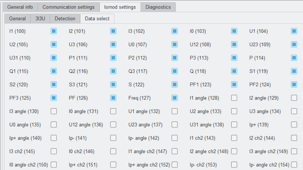
Data select tab (Fig. 5.3.1) is the last IOMod settings section, which provides a way to control the data being sent via IEC 60870-5-101 communication protocol. The IOA (Information Object Address) of each data unit is specified in the brackets to the right of a parameter's name. In order to include a parameter to a set of parameters which are sent via IEC 60870-5-101 communication protocol a checkbox to the right of a parameter's name needs to be checked.
Fig. 5.3.1 IOMod FPI Data select tab view
5.4 Diagnostics
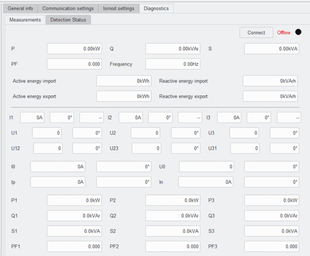
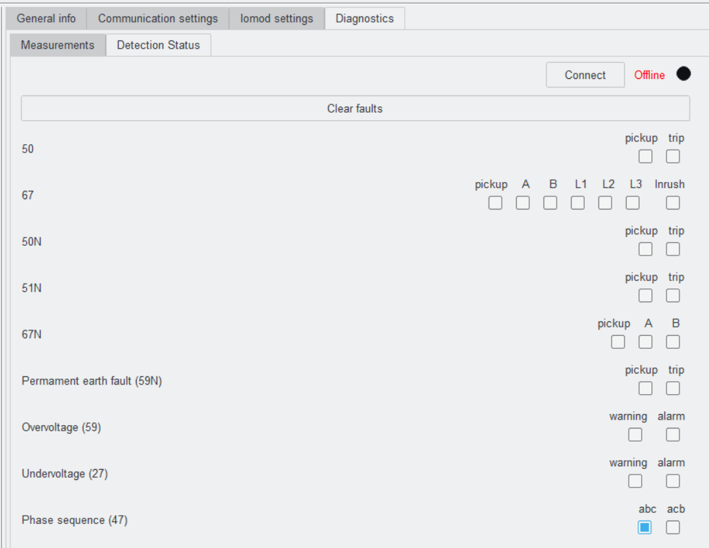
IOMod Utility Diagnostics tab allows real-time monitoring of IOMod FPI measurements and detection function statuses. The diagnostics mode of both measurements and detection statuses is turned off by default. This is indicated by the red "Offline" word designation and by the unchanging black circle (Fig. 5.4.1, Fig. 5.4.2).
Fig. 5.4.1 IOMod Utility Diagnostics tab Measurement section in offline mode
Fig. 5.4.2 IOMod Utility Diagnostics tab Detection Status section in offline mode
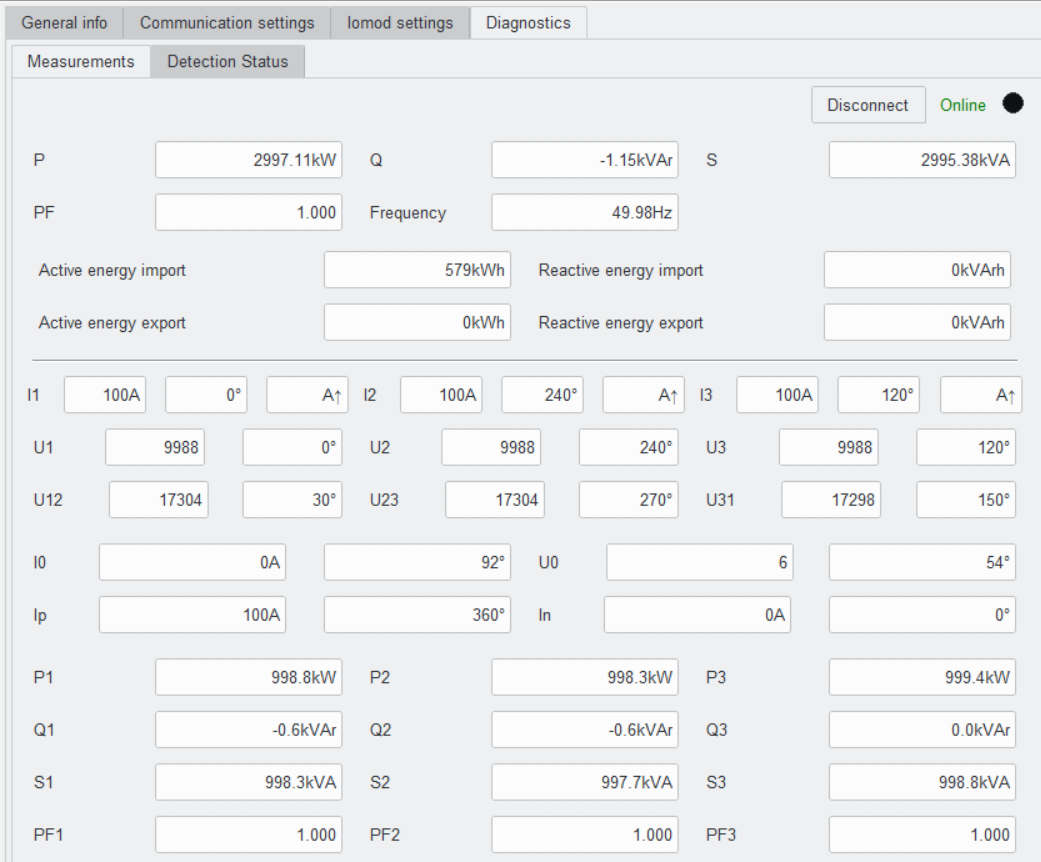
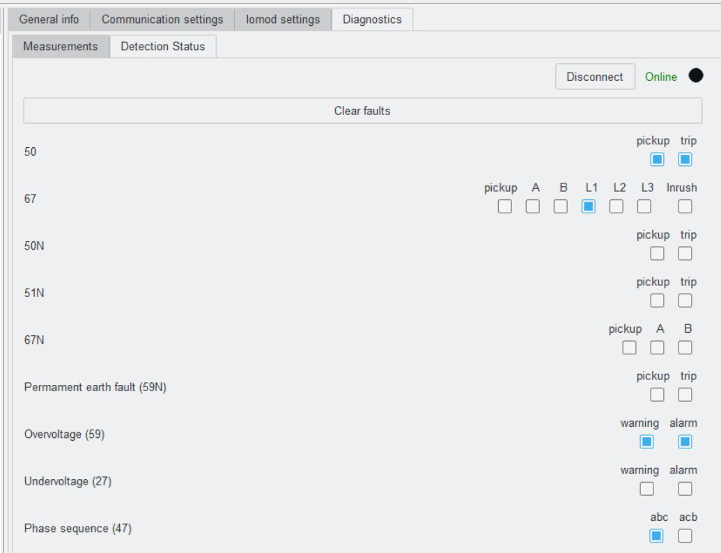
In order to turn on real-time monitoring of both Diagnostics sections, "Connect" button to the left of "Offline" word designation needs to be pressed. The button can be pressed in either Diagnostics sections (Measurements or Detection Status). After pressing "Connect" button the word designation of Diagnostics mode changes to "Online", the black circle starts blinking and the button name changes to "Disconnect" (Fig. 5.4.3, Fig. 5.4.4). When a fault is detected the checkboxes which are opposite the according detection functions are going to be checked (Fig. 5.4.4).
Fig. 5.4.3 IOMod Utility Diagnostics tab Measurement section in online mode
Fig. 5.4.4 IOMod Utility Diagnostics tab Detection status section in online mode
It is advisable to turn off Diagnostics mode before setting new IOMod FPI parameters. In order to turn off Diagnostics real-time monitoring mode, "Disconnect" button needs to be pressed.
6. Device functions
6.1 Instantaneous overcurrent detection function (50)
It is a three phase overcurrent detection function with the definite time characteristic. This function is intended for detecting electrical faults in medium voltage three phase networks, e.g. short circuits and overloading.
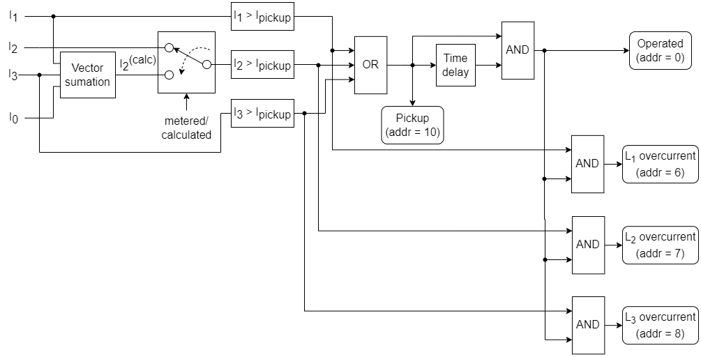
During the instantaneous overcurrent detection process (Fig. 6.1.1) RMS value of each phase fundamental frequency current is constantly being obtained. While first and third phase currents are always measured, the way of obtaining RMS values of the second phase is dependent upon neutral current value obtaining mode. In case of I0 metered mode the RMS value of the second phase current is being calculated as a vector sum of the I1, I3 and I0 current values. If instead the neutral current is being calculated, then the current of the second phase is being measured. After obtaining current level values they are being compared with a configured threshold designated as Ipickup. If a phase current in any line exceeds Pickup current Ipickup, then "Instantaneous overcurrent function (50) pickup" signal with the address 10 is issued (Table 7.1.1, Table 7.2.1, Table 7.3.1). The further actions are delayed by a preconfigured amount of time to filter out any momentary current level spikes. If the level of a phase current in any line remains higher than Ipickup for a time longer than a Time delay parameter value specifies, then “Instantaneous overcurrent function (50) operated” signal with the address 0 is issued. Finally, from one to three signals are sent identifying the line or the lines in which the overcurrent conditions were detected: "Overcurrent fault in the first phase (L1)" with the address 6, "Overcurrent fault in the second phase (L2)" with the address 7, "Overcurrent fault in the third phase (L3)" with the address 8.
Fig. 6.1.1 Instantaneous overcurrent protection function algorithm structural diagram
The instantaneous overcurrent detection function has two main parameters (Table 6.1.1): Pickup current and Time delay. The table below describes the range and default values of the parameters.
Table 6.1.1 Instantaneous overcurrent protection function
related parameters with their ranges and default values
|
Parameter |
Range |
Default value |
|---|---|---|
|
50 I> |
Enabled / Disabled |
Disabled |
|
Pickup current (A) |
1–1000 |
300 |
|
Time delay (ms) |
40–60000 |
100 |
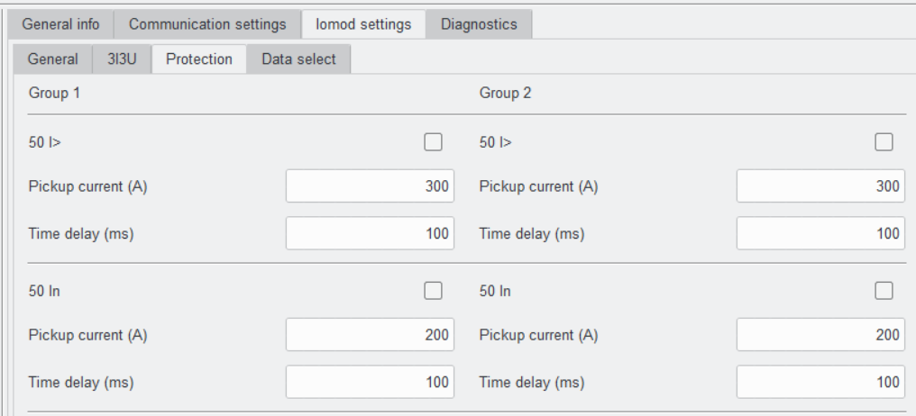
IOMod Utility is required to enable the instantaneous overcurrent detection in FPI. In IOMod Utility go to Iomod settings -> Protection. There find "50 I>" function. Modify the parameters if required and tick the box next to the function name to enable it (Fig 6.1.2).

Fig. 6.1.2 IOMod Utility instantaneous overcurrent detection function configuration view
6.2 Instantaneous overcurrent earth fault detection function (50N)
It is a residual ground overcurrent detection function with definite time characteristic. This function is intended for phase to ground fault detection in medium voltage three phase networks.
During the instantaneous overcurrent earth fault detection process (Fig. 6.2.1) RMS value of fundamental frequency neutral current is constantly being obtained. Two modes of obtaining RMS values of the neutral current are available: metered and calculated. In case of I0 metered mode the neutral current is being measured directly. In the "calculated" mode the neutral current is being calculated as a vector sum of three phase current values. After obtaining neutral current level it is compared with the configured threshold Ipickup. If the neutral current exceeds Pickup current Ipickup, "Instantaneous overcurrent earth fault function (50N) pickup" signal with the address 11 (Table 7.1.1, Table 7.2.1, Table 7.3.1) is issued. The further actions are delayed by a preconfigured amount of time to filter out any momentary current level spikes. If the level of the neutral current remains higher than Ipickup for a time longer than a Time delay parameter specifies, then “Instantaneous overcurrent earth fault function (50N) operated” signal with the address 1 is issued.
Fig. 6.2.1 Instantaneous overcurrent earth fault protection function algorithm structural diagram
The instantaneous overcurrent earth fault detection function has two main parameters (Table 6.2.1): Pickup current and Time delay. The table below describes the range and default values of the parameters.
Table 6.2.1 Instantaneous overcurrent earth fault protection function
related parameters with their ranges and default values
|
Parameter |
Range |
Default value |
|---|---|---|
|
50 In |
Enabled / Disabled |
Disabled |
|
Pickup current (A) |
1–1000 |
200 |
|
Time delay (ms) |
40–60000 |
100 |
IOMod Utility is required to enable the instantaneous overcurrent earth fault detection in FPI. In IOMod Utility go to Iomod settings -> Protection. There find "50 In" function. Modify the parameters (Table 6.2.1) if required and tick the box next to the function name to enable it (Fig 6.2.2).
Fig. 6.2.2 IOMod Utility instantaneous overcurrent earth fault
detection function configuration view
6.3 Undervoltage detection function (27)
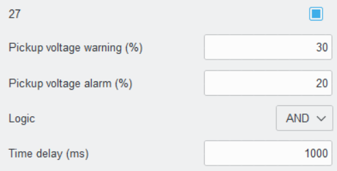
Undervoltage detection function is intended for detecting abnormally low voltage levels in three phase networks. The function defines two thresholds in relative units (Table 6.3.1, Fig. 6.3.3) – "Pickup voltage warning (%)" and "Pickup voltage alarm (%)". Based on which threshold is surpassed warning or alarm signal is sent respectively (Fig 6.3.1, Fig 6.3.2).
Fig. 6.3.1. Warning-level undervoltage detection function algorithm structural diagram
Fig. 6.3.2 Alarm-level undervoltage detection function algorithm structural diagram
Each phase voltage is constantly being monitored and compared with each of previously mentioned thresholds. The subsequent operation depends on the selected logic. The "Logic" parameter (Table 6.3.1, Fig. 6.3.2) defines the conditions when the alarm or warning signal is issued. If “Logic” parameter is set to “AND”, a warning or alarm is triggered if the voltage level in all of the three phases falls below the respective threshold value. If “Logic” is set to “OR”, a warning or alarm is triggered if the voltage level in any of the three phases falls below the respective threshold value. The further sending of a certain signal is delayed by a configured amount of time to filter out any momentary voltage level dips. If after the time delay the voltage level remains lower than one of the pickup thresholds, warning or alarm signal is sent. The "Undervoltage (27) warning" signal, assigned to address 18 (Fig. 6.3.1), is triggered if any or all nominal voltage levels drop by the percentage defined in the “Pickup Voltage Warning (%)” parameter. Similarly, the "Undervoltage (27) alarm" signal, assigned to address 19 (Fig 6.3.2), is sent if any or all nominal voltage levels drop by the percentage defined in the “Pickup Voltage Alarm (%)” parameter.
The undervoltage detection function has four parameters (Table 6.3.1): Pickup voltage warning, Pickup voltage alarm, Logic and Time delay. The table below describes the range and default values of the parameters.
Table 6.3.1 Undervoltage detection function related parameters
with their ranges and default values
|
Parameter |
Range |
Default value |
|---|---|---|
|
27 |
Enabled / Disabled |
Disabled |
|
Pickup voltage warning (%) |
1–100 |
30 |
|
Pickup voltage alarm (%) |
1–100 |
20 |
|
Logic |
AND / OR |
AND |
|
Time delay (ms) |
40–60000 |
1000 |
IOMod Utility is required to enable the undervoltage detection in FPI. In IOMod Utility go to Iomod settings -> Protection. There find "27" function. Modify the parameters if required and tick the box next to the function name to enable it (Fig 6.3.2).
Fig. 6.3.3 IOMod Utility undervoltage detection function configuration view
6.4 Overvoltage detection function (59)
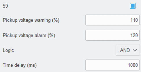
Undervoltage detection function is intended for detecting abnormally high voltage levels in three phase networks. The function defines two thersholds in relative units (Table 6.4.1, Fig. 6.4.3) – "Pickup voltage warning (%)" and "Pickup voltage alarm (%)". Based on which threshold is surpassed warning or alarm signal is sent respectively (Fig 6.4.1, Fig 6.4.2).
Fig. 6.4.1 Warning-level overvoltage detection function algorithm structural diagram
Fig. 6.4.2 Alarm-level overvoltage detection function algorithm structural diagram
Each phase voltage is constantly being monitored and compared with each of previously mentioned thresholds. The subsequent operation depends on the selected logic. The "Logic" parameter (Table 6.4.1, Fig. 6.4.3) defines the conditions when the alarm or warning signal is issued. If “Logic” parameter is set to “AND”, a warning or alarm is triggered if the voltage level in all of the three phases exceeds the respective threshold value. If “Logic” is set to “OR”, a warning or alarm is triggered if the voltage level in any of the three phases exceeds the respective threshold value. The further sending of one of the signals is delayed by a configured amount of time to filter out any momentary voltage level spikes. If after the time delay the voltage level remains higher than one of the pickup thresholds, warning or alarm signal is sent. The "Overvoltage (59) warning" signal, assigned to address 16 (Fig. 6.4.1), is triggered if any or all nominal voltage levels increases by the percentage defined in the “Pickup Voltage Warning (%)” parameter. Similarly, the "Overvoltage (59) alarm" signal, assigned to address 17 (Fig 6.4.2), is sent if any or all nominal voltage levels increases by the percentage defined in the “Pickup Voltage Alarm (%)” parameter.
The overvoltage detection function has four parameters (Table 6.4.1): Pickup voltage warning, Pickup voltage alarm, Logic and Time delay. The table below describes the range and default values of the parameters.
Table 6.4.1 Overvoltage detection function related parameters
with their ranges and default values
|
Parameter |
Range |
Default value |
|---|---|---|
|
59 |
Enabled / disabled |
Disabled |
|
Pickup voltage warning (%) |
100–200 |
110 |
|
Pickup voltage alarm (%) |
100–200 |
120 |
|
Logic |
AND / OR |
AND |
|
Time delay (ms) |
40–60000 |
1000 |
IOMod Utility is required to enable the overvoltage detection in FPI. In IOMod Utility go to Iomod settings -> Protection. There find "59" function. Modify the parameters if required and tick the box next to the function name to enable it (Fig 6.4.2).
Fig. 6.4.3 IOMod Utility overvoltage detection function configuration view
6.5 Earth fault overvoltage detection (59N)
Earth fault overvoltage detection function is intended for detecting abnormally high level of zero sequence voltage in three phase networks. The neutral voltage is being calculated by taking the vector sum of fundamental frequency components of measured voltages (Fig 6.5.1). The calculated neutral voltage is constantly being compared with the neutral voltage thershold value Upickup. The value of Upickup is calculated by taking percentage, which is defined in "Pickup voltage (%)" parameter, of its nominal value. Right after detecting a neutral voltage which crosses Upickup limit, the "Residual overvoltage (59N) pickup" signal, assigned to address 15, is sent. The further sending of "operated" signal is delayed by a configured amount of time to filter out any momentary neutraul voltage spikes. If the level of the neutral voltage remains higher than Upickup for the time longer than a Time delay parameter specifies, then “Residual overvoltage (59N) operated” signal, assigned to address 9, is issued.
Fig. 6.5.1 Earth fault overvoltage detection function algorithm structural diagram
The overvoltage detection function has two parameters (Table 6.5.1): Pickup voltage and Time delay. The table below describes the range and default values of the parameters.
Table 6.5.1 Overvoltage detection function related parameters
with their ranges and default values
|
Parameter |
Range |
Default value |
|---|---|---|
|
59N |
Enabled / disabled |
Disabled |
|
Pickup voltage (%) |
0–100 |
30 |
|
Time delay (ms) |
40–60000 |
10000 |
IOMod Utility is required to enable the earth fault overvoltage detection in FPI. In IOMod Utility go to Iomod settings -> Protection. There find "59N" function. Modify the parameters if required and tick the box next to the function name to enable it (Fig 6.5.2).
Fig. 6.5.2 IOMod Utility earth fault overvoltage detection function configuration view
6.6 Directional overcurrent detection function (67)
It is a directional phase fault detection function with definite or inverse time characteristic. This function is intended for detecting phase faults in medium voltage three phase networks with fault direction determination.
The directional overcurrent detection function has six parameters (Table 6.6.1): Pickup current, IDMT curve, TMS, Time delay, Correction angle and Inrush blocking. The table below describes the range and default values of the parameters.
Table 6.6.1 Directional phase fault detection function parameters.
|
Parameter |
Range |
Default value |
|---|---|---|
|
67/51 |
Enabled / disabled |
Disabled |
|
Pickup current (A) |
1–1000 |
200 |
|
IDMT curve |
Time delay* |
Standard inverse |
|
Standard inverse |
||
|
Very inverse |
||
|
Extremely inverse |
||
|
Long time inverse |
||
|
TMS (time multiplier) |
0.01–100 |
1 |
|
Time delay (ms) |
40–60000 |
100 |
|
Correction angle (MTA) |
-80°… 80° |
-45° |
|
Inrush blocking |
Enabled / Disabled |
Enabled |
* Definite time delay
IOMod Utility is required to enable the directional overcurrent detection in FPI. In IOMod Utility go to Iomod settings -> Protection. There find "67/51" function. Modify the parameters if required and tick the box next to the function name to enable it (Fig 6.6.2).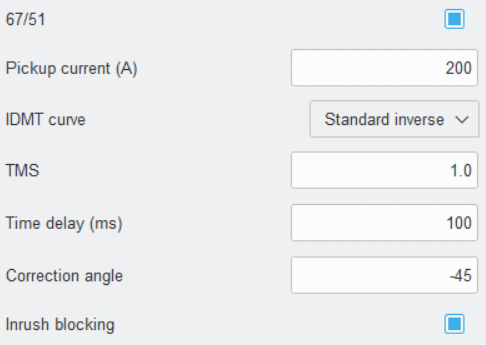
Fig. 6.6.1 IOMod Utility directional overcurrent detection function configuration view
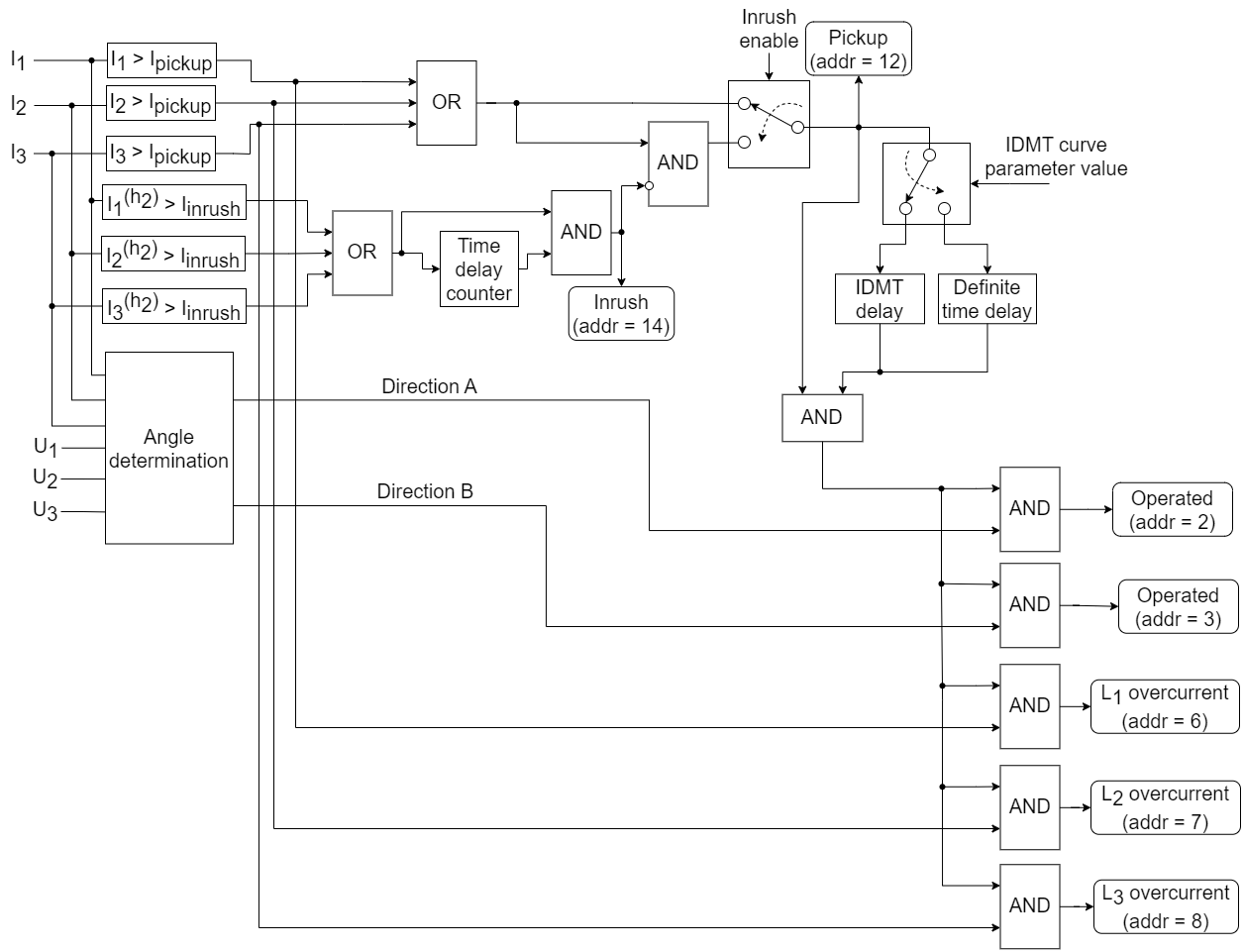
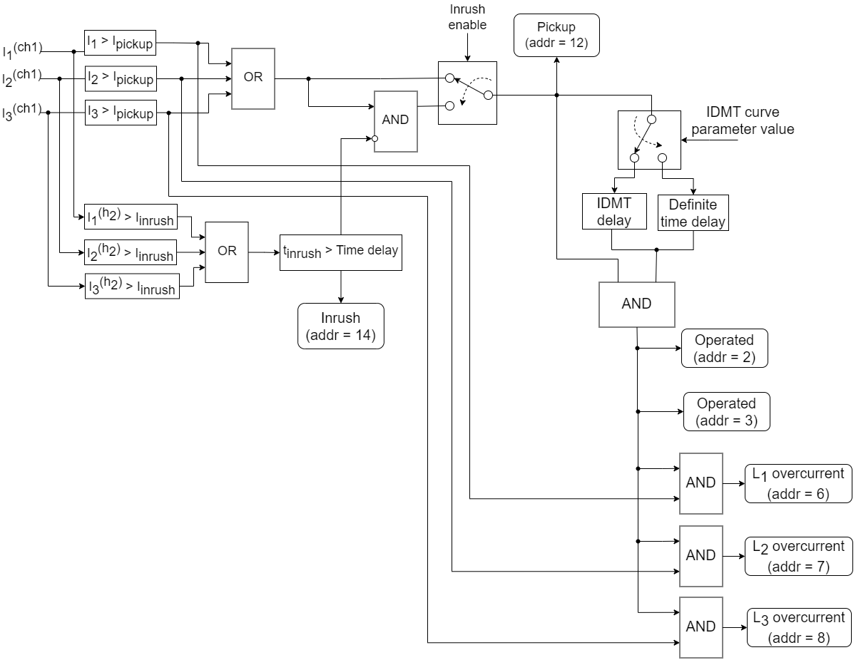
Describing directional overcurrent detection function algorithm, it is important to notice that both current and voltage measurements are required (Fig 6.6.3). Similarly to Instantaneous overcurrent function (50), each phase currents are being continually measured and compared with the preconfigured Pickup current value Ipickup. Assuming that Inrush check is disabled, after detecting the crossing of Ipickup by any of the currents, "Directional overcurrent function (67) pickup" signal, assigned to address 12, is sent. If the Inrush blocking detection function (81) is enabled, the second harmonic of each phase is obtained and compared to Ih2/Ih1 parameter value (Table 6.6.3.1). The level of a current second harmonic must exceed the Inrush threshold value for a time longer than Time delay parameter specifies. If these conditions are fulfilled, then the Inrush current is detected and "Blocking by 2nd harmonic active" signal with address 14 is issued. The detection of the Inrush current blocks the subsequent operation and the "Directional overcurrent function (67) pickup” signal is not sent.
Fig. 6.6.2 Directional overcurrent detection function algorithm structural diagram
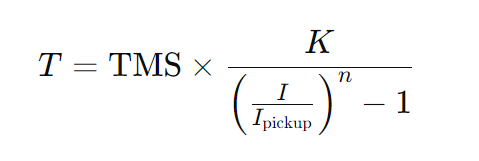
Similarly to the function 50 overcurrent detection activation signal is postponed by a preconfigured time, in order to filter any short-term current spikes. However, this time apart from definite time delay, there is an option to set Inverse Definite Minimum Time (IDMT) delay. In contrast to the Definite time delay, IDMT delay period depends on the overcurrent amplitude. The bigger the overcurrent amplitude, the shorter the delay. IDMT time delay can be calculated by using the formula below:
Where:
- T – operating time of the relay (in seconds)
- TMS – Time Multiplier Setting (adjusts the speed of operation)
- K – Constant specific to the IDMT curve type (depends on the curve type, Table 6.6.2)
- I – Fault current (in amperes)
- Ipickup – Pickup current (in amperes)
- n – Characteristic exponent (depends on the curve type, see Table 6.6.2)
IEC 60255 standard describes four main curve characteristics (Table 6.6.2). Each characteristic defines a unique pair of K and n coefficients:
Table 6.6.2 Parameters of IEC Characteristic Curves.
|
Curve Type |
K |
n |
|---|---|---|
| Standard (Normal) Inverse | 0.14 | 0.02 |
| Very Inverse | 13.5 | 1 |
| Extremely Inverse | 80 | 2 |
| Long Time Inverse | 120 | 1 |
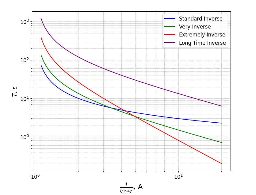
Plotting all four curve types helps to visualize how the time delay depends on the fault current for each characteristic, providing a clear comparison of their different response behaviors (Fig. 6.6.4). All curves were calculated with TMS parameter set to 1.
Fig. 6.6.3 IDMT Time Delay dependence on the fault current graphs (with TMS=1)
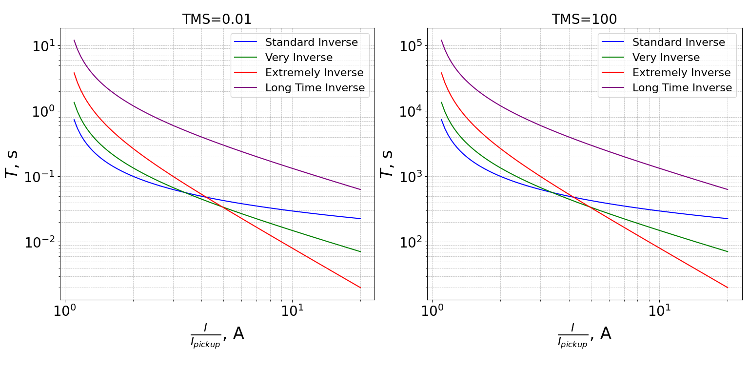
IDMT time delay characteristics can be adjusted by changing TMS values. Decreasing or increasing TMS value changes the vertical position of IDMT curves placing them lower or higher respectively (Fig. 6.6.5). In other words, by decreasing or increasing the TMS value, you can make the time delay shorter or longer, respectively.
Fig. 6.6.4 The effect of TMS parameter on IDMT curves (on the left: TMS=0.01, on the right: TMS=100)
Setting IDMT curve value to "Time delay" switches to Definite time delay mode. In this mode time delay value is constant and does not depend on the fault current. The value of the constant time delay is adjusted by the "Time delay (ms)" parameter (Fig. 6.6.2).
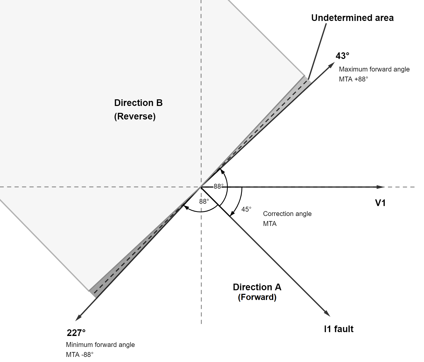
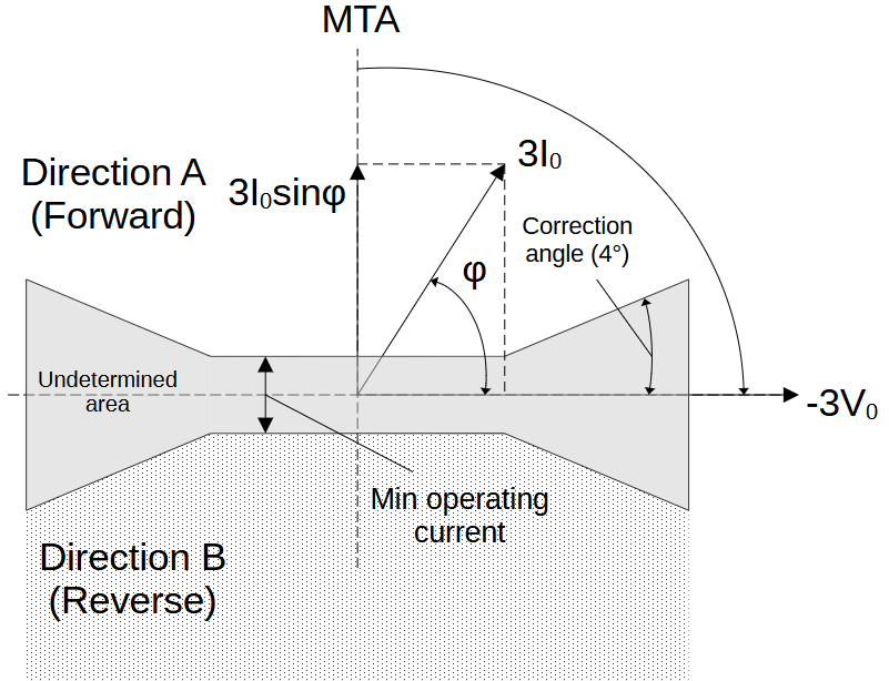
Besides the overcurrent detection, the direction of the fault current is determined. In order to be able to provide directional overcurrent fault information RMS values and the phase angles of the fundamental frequency currents and voltages are constantly being measured. Quadrature voltages are used for determining the direction of a fault, e.g. for determining the direction of the first phase current I1 fault phase to phase voltage U23 is used. Based on the angle between the voltage and current, the relay can distinguish between Direction A (forward) and Direction B (reverse). In most power systems, Direction A would be the flow of current towards the load or downstream side (away from the source). On the other hand, Direction B would be the flow of current back towards the source or upstream side (against the normal flow of current). The minimal voltage level for which direction determination still can be performed is 10 % of nominal. The characteristic angle or so-called maximum torque angle (MTA) can be set by a user (Table 6.6.1, Fig. 6.6.2). It defines the angle between a phase current and a corresponding phase voltage (Fig. 6.6.1). Typically, a phase fault is inductive in its nature, meaning that current lags voltage, therefore default value of “Correction angle” parameter is set to -45°. Forward direction (dir A) zone is in window “Correction angle” +/- 88°, reverse direction (dir B) zone is in opposite +/- 88° window, 4° gap between forward and reverse zones is an undetermined area. If polarization voltage is below 10 % or the angle between the fault current and voltage is in the undetermined area, then function works as non-directional overcurrent function and activates both directional elements, i.e. A and B.
Fig. 6.6.5 Overcurrent direction determination phasor diagram
If after a Time delay the level of the fault current in any line remains higher than Ipickup, then, depending on the fault direction, "Overcurrent function (67) direction A operated" signal, assigned to address 2, or "Overcurrent function (67) direction B operated" signal, assigned to address 3, is issued. However, if the direction could not be determined both signals are going to be issued. Also, simillarly to the function 50, from one to three signals are sent identifying the line or the lines in which the overcurrent conditions were detected: "Overcurrent fault in the first phase (L1)" (assigned to address 6), "Overcurrent fault in the second phase (L2)" (assigned to address 7), "Overcurrent fault in the third phase (L3)" (assigned to address 8).
6.6.1 Inverse time overcurrent detection function (51)
By switching to 3I3I connection mode the detection function 67 becomes the detection function 51. Their operational algorithms are quite similar (Fig. 6.6.1.1), but the absence of the voltage measurements brings some important differences. Each phase currents of two feeders are continually measured and compared with the preconfigured Pickup current value Ipickup. The Pickup current can be separately configured for each channel.
In the context of the first channel (Fig. 6.6.1.1), if the Inrush check is disabled, after detecting the crossing of Ipickup by any of the currents, "Directional overcurrent function (67) pickup" signal, assigned to address 12, is sent. If the Inrush blocking detection function (81) is enabled, the second harmonic of each phase is obtained and compared to Ih2/Ih1 parameter value (Table 6.6.3.1). The level of a current second harmonic must exceed the Inrush threshold value for a time longer than Time delay parameter specifies. If these conditions are fulfilled, then the Inrush current is detected and "Blocking by 2nd harmonic active" signal with address 14 is issued. The detection of the Inrush current blocks the subsequent operation and the "Directional overcurrent function (67) pickup" signal is not sent. Assuming that an overcurrent was detected and was not blocked by an Inrush current, the subsequent operation is delayed by a definite or inverse time period. Since the voltage measurements are not obtained, the fault direction cannot be determined. Due to this fact, if the overcurrent is still detected after the time delay, two signals are sent: "Overcurrent function (67) direction A operated", assigned to address 2, and "Overcurrent function (67) direction B operated", assigned to address 3, identifying both directions. Also, from one to three signals are sent identifying the line or the lines in which the overcurrent conditions were detected: "Overcurrent fault in the first phase (L1)" (assigned to address 6), "Overcurrent fault in the second phase (L2)" (assigned to address 7), "Overcurrent fault in the third phase (L3)" (assigned to address 8).
Fig. 6.6.1.1 Inverse time overcurrent first channel detection function algorithm structural diagram
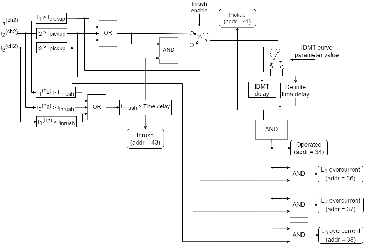
In case of the second channel (Fig. 6.6.1.2), if the Inrush check is disabled or Inrush current is not detected, after detecting the crossing of Ipickup by any of the currents, "Time inverse overcurrent function (51) pickup in channel 2" signal, assigned to address 41, is sent. Assuming that an inrush current was detected in any of phases, the subsequent operation is blocked and "Blocking by 2nd harmonic active in channel 2" signal, assigned to address 43 is issued. Assuming that an overcurrent was detected and was not blocked by an Inrush current, the subsequent operation is delayed by a definite or inverse time period. Contrary to the first channel, if the overcurrent is still detected after the time delay, only one signal is issued: "Time inverse overcurrent function (51) operated in channel 2", assigned to address 34. Also, from one to three signals are sent identifying the line or the lines in which the overcurrent conditions were detected: "Overcurrent fault in phase L1 of channel 2" (assigned to address 36), "Overcurrent fault in phase L2 of channel 2" (assigned to address 37), "Overcurrent fault in phase L3 of channel 2" (assigned to address 38).
Fig. 6.6.1.2 Inverse time overcurrent second channel detection function algorithm structural diagram
The inverse time overcurrent detection function has five parameters (Table 6.6.1.1): Pickup current, IDMT curve, TMS, Time delay and Inrush blocking. The table below describes the range and default values of the parameters.
Table 6.6.1.1 Inverse time overcurrent detection function parameters.
|
Parameter |
Range |
Default value |
|---|---|---|
|
51 |
Enabled / disabled |
Disabled |
|
Pickup current (A) |
1–1000 |
200 |
|
IDMT curve |
Time delay (IDMT off) |
Standard inverse |
|
Standard inverse |
||
|
Very inverse |
||
|
Extremely inverse |
||
|
Long time inverse |
||
|
TMS (time multiplier) |
0.01–100 |
1.0 |
|
Time delay (ms) |
40–60000 |
100 |
|
Inrush blocking |
Enabled / Disabled |
Enabled |
IOMod Utility is required to enable the directional overcurrent detection in FPI. In IOMod Utility go to Iomod settings -> Protection. There find "51" function. Modify the parameters if required and tick the box next to the function name to enable it (Fig. 6.6.1.3).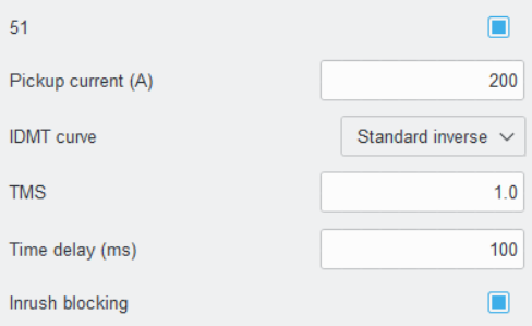
Fig. 6.6.1.3 IOMod Utility inverse time overcurrent
detection function configuration view
6.6.2 Inverse time overcurrent earth fault detection function (51N)
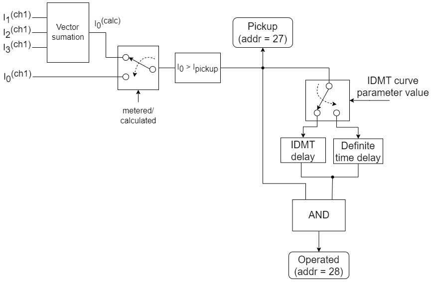
In the 3I3I connection mode the Inverse time overcurrent earth fault detection function (51N) is available. This function algorithm (Fig. 6.6.2.1, Fig. 6.6.2.2) is similar to the Instantaneous overcurrent earth fault detection function (50N) algorithm (Fig. 6.2.1). The key differences of function 51N are the presence of two channels and the ability to select between the Inverse time or Definite time delays. Similarly to the function 50N, RMS value of fundamental frequency neutral current is constantly being obtained. Two modes of obtaining RMS values of the neutral current are available: metered and calculated. In the case of I0 metered mode the neutral current is being measured directly. In the "calculated" mode the neutral current is being calculated as a vector sum of three phase current values. After obtaining neutral current level it is compared with the configured threshold Ipickup. The Pickup current and Time delay parameters can be separately configured for each channel.
In case of the first channel (Fig. 6.6.2.1), if the neutral current exceeds Pickup current Ipickup, "Time inverse overcurrent earth fault function (51N) pickup" signal with the address 27 is issued. The subsequent operation is delayed by a definite or inverse time period. If the earth fault conditions remains after the time delay, "Time inverse overcurrent earth fault function (51N) operated" signal with address 28 is issued.
Fig. 6.6.2.1 Inverse time overcurrent earth fault first channel detection function algorithm structural diagram
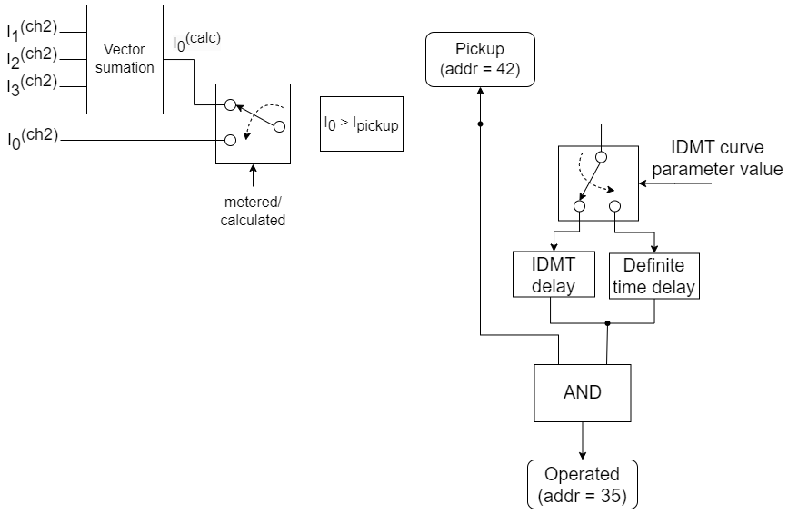
In the context of the second channel (Fig. 6.6.2.2), if the neutral current exceeds Pickup current Ipickup, "Time inverse overcurrent earth fault function (51N) pickup in channel 2" signal, assigned to address 42, is issued. The subsequent operation is delayed by a definite or inverse time period. If the earth fault conditions remains after the time delay, "Time inverse overcurrent earth fault function (51N) operated in channel 2" signal, assigned to address 35, is issued.
Fig. 6.6.2.2 Inverse time overcurrent earth fault second channel detection function algorithm structural diagram
The inverse time overcurrent earth fault detection function has four parameters (Table 6.6.2.1): Pickup current, IDMT curve, TMS and Time delay. The table below describes the range and default values of the parameters.
Table 6.6.2.1 Inverse time overcurrent earth fault detection function parameters.
|
Parameter |
Range |
Default value |
|---|---|---|
|
51N |
Enabled / disabled |
Disabled |
|
Pickup current (A) |
1–1000 |
200 |
|
IDMT curve |
Time delay (IDMT off) |
Standard inverse |
|
Standard inverse |
||
|
Very inverse |
||
|
Extremely inverse |
||
|
Long time inverse |
||
|
TMS (time multiplier) |
0.01–100 |
1.0 |
|
Time delay (ms) |
40–60000 |
100 |
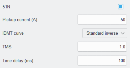
IOMod Utility is required to enable the directional overcurrent detection in FPI. In IOMod Utility go to Iomod settings -> Protection. There find "51N" function. Modify the parameters if required and tick the box next to the function name to enable it (Fig. 6.6.2.3).
Fig. 6.6.2.3 IOMod Utility inverse time overcurrent
earth fault detection function configuration view
6.6.3 Inrush blocking detection function (81)
Directional phase fault detection function (67) has inrush blocking functionality. If the function is enabled, the 2nd harmonic level of a phase current is monitored. If a phase current 2nd harmonic level is higher than a configured threshold value for a longer time than the "Time delay" parameter specifies, then Inrush current is detected and the overcurrent in any line is ignored (see Fig 6.6.3, Fig. 6.6.1.1 and Fig. 6.6.1.2). Notice that the function cannot be enabled separately, because it works as a part of over detection functions, namely: 67 and 51. This function can be enabled by the "Inrush blocking" checkbox, which can be found in the settings of 67 and 51 functions (Fig. 6.6.1, Fig. 6.6.1.3).
Table 6.6.3.1 Inrush blocking parameters.
|
Parameter |
Range |
Default value |
|---|---|---|
|
Ih2/Ih1 (2nd harmonic level) |
0–100 % |
15 % |
|
Time delay (ms) |
40–60000 |
100 |
IOMod Utility is required to control the operation of the inrush blocking detection function in FPI. In IOMod Utility go to Iomod settings -> Protection. There find "81 Inrush" function. Modify the parameters if required (Fig 6.6.3.1).
Fig. 6.6.3.1 IOMod Utility inrush blocking detection function configuration view
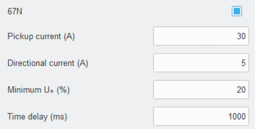
6.7 Directional overcurrent earth fault detection function (67N)
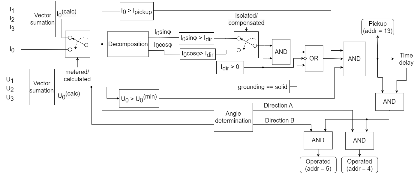
It is a ground fault detection function with definite time characteristic and fault direction determination. This function is intended for detecting phase to ground faults in medium voltage three phase networks. In order to provide directional overcurrent earth fault information, the ground current and the residual voltage are constantly being monitored. The ground fault current is calculated as the value of the vector sum of the three phase currents or measured with zero sequence current transformer (core balanced CT – CBCT) (Fig. 7.6.1). Residual voltage is always calculated as vector sum of three phase voltages. Three conditions must be met for the "Directional earth fault function (67N) pickup" signal, assigned to address 13, to be issued. Firstly, the ground fault current I0 must exceed the pickup current Ipickup. Secondly, the relative residual voltage U0 must exceed the “Minimum U0 (%)" parameter value. The relative residual voltage is calculated relatively to the nominal value of a phase current. In case when "Directional Current (A)" parameter is set to 0 or Grounding parameter is set to "Solid" (see Fig. 5.1.1), the fulfillment of the two previous conditions is sufficient for the "Pickup" signal to be sent. In the other case, for the "Pickup" signal to be sent, the specific component of the fault current must be greater than the directional current parameter Idir value. The usage of the ground fault current components for ground fault current detection is going to be discussed later in detail. The angle and the direction of the fault current are determined by using the ground fault current along with the residual voltage. The angle depends on the network grounding method: solid, isolated or compensated. The correction angle of solidly grounded system is equal to -45° and cannot be configured. The direction of the fault current can be either A (forward) or B (reverse). In most power systems, Direction A would be the flow of current towards the load or downstream side (away from the source). On the other hand, Direction B would be the flow of current back towards the source or upstream side (against the normal flow of current). If the pickup conditions persist for a time longer than “Time delay” parameter specifies, then, depending on the fault direction, "Earth fault (67N) direction A operated" signal, assigned to address 4, or "Earth fault (67N) direction B operated" signal, assigned to address 5, is issued.
Fig. 6.7.1 Directional overcurrent earth fault detection function algorithm structural diagram
In addition to the vector based method there is a posibility to enable sin(φ) or cos(φ) method for ground fault detection using the directional current (Idir) parameter. However, these methods are applicable for isolated or compensated ground networks only. The directional current Idir defines the thresholds of the reactive I0sin(φ) part or the active I0cos(φ) of the ground current for the isolated ground or the resonant grounding networks respectively. In case of an isolated-ground network (Fig. 6.7.2) the device indicates the earth fault when the total ground current and the reactive current I0sin(φ) is higher than the pickup current Ipickup and the directional current Idir for a time longer that “Time delay” parameter specifies. However, if the directional current Idir is set to 0, only total ground current is used for the fault detection.
Fig. 6.7.2 'I0sin' characteristic for an isolated neutral network
For a resonant (or 'compensated ') grounding network (Fig. 6.7.3) the device indicates the earth fault when total ground current and active current I0cos(φ) is bigger that the pickup current Ipickup and the directional current Idir for a time longer that “Time delay” parameter specifies. However, if the directional current Idir is set to 0, only total ground current is used for the fault detection.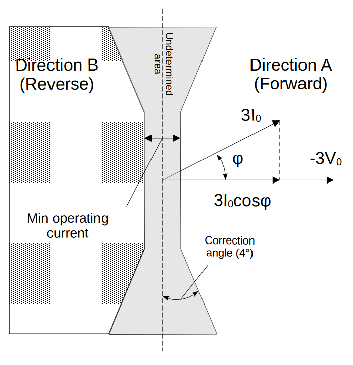
Fig. 6.7.3 'I0cos' characteristic for a resonant network
The directional overcurrent earth fault detection function has four parameters (Table 6.7.1): Pickup current, Directional current, Minimum U0 and Time delay. The table below describes the range and default values of the parameters.
Table 6.7.1 Directional earth fault detection function parameters.
|
Parameter |
Range |
Default value |
|---|---|---|
|
67N |
Enabled / disabled |
Disabled |
|
Pickup Current (A) |
0–1000 |
30 |
|
Directional Current (A) |
0–1000 |
5 |
|
Minimum U0 (%) |
0–100 |
20 |
|
Time delay (ms) |
40–60000 |
1000 |
IOMod Utility is required to enable the directional overcurrent earth fault detection in FPI. In IOMod Utility go to Iomod settings -> Protection. There find "67N" function. Modify the parameters if required and tick the box next to the function name to enable it (Fig 6.7.4).
Fig. 6.7.4 IOMod Utility directional overcurrent earth fault
detection function configuration view
7. Communication protocols
IOMod FPI supports three communication protocols: Modbus RTU, IEC 60870-5-101 and IEC 60870-5-103. By means of these communication protocols a user via a master device is able to read from the device the measured data as well as fault detection statuses. Also, the protocols allow a master device to send a command to clear fault detection statuses. Communication protocol can be selected by means of IOMod Utility (IOmod Utility manual can be accessed here).
7.1 Modbus RTU operational information
Modbus RTU protocol is a simple and widely used messaging structure for serial communication. In the case of Modbus protocol IOMod FPI will send data only after receiving correct queries from a master device.
Only three function codes are supported: FC2, FC4 and FC5. Read Discrete Inputs function, which is denoted by function code 2 (FC2), as its name implies is designed for reading digital data. In the context of IOMod FPI FC2 requests allow to read fault detection statuses (Table 7.1.1). It should be noted that the fault statuses cannot be overwritten separately but can only be read (R access).
Table 7.1.1 List of discrete inputs with fault detection statuses. The data can be read using Modbus FC2 request.
|
Address (Dec) |
Description |
Access |
|
0 |
Instantaneous overcurrent function (50) operated |
R |
|
1 |
Instantaneous overcurrent earth fault function (50N) operated |
R |
|
2 |
Overcurrent function (67) direction A operated |
R |
|
3 |
Overcurrent function (67) direction B operated |
R |
|
4 |
Earth fault (67N) direction A operated |
R |
|
5 |
Earth fault (67N) direction B operated |
R |
|
6 |
Overcurrent fault in the first phase (L1) |
R |
|
7 |
Overcurrent fault in the second phase (L2) |
R |
|
8 |
Overcurrent fault in the third phase (L3) |
R |
|
9 |
Residual overvoltage (59N) operated |
R |
|
10 |
Instantaneous overcurrent function (50) pickup |
R |
|
11 |
Instantaneous overcurrent earth fault function (50N) pickup |
R |
|
12 |
Directional overcurrent function (67) pickup |
R |
|
13 |
Directional earth fault function (67N) pickup |
R |
|
14 |
Blocking by 2nd harmonic active |
R |
|
15 |
Residual overvoltage (59N) pickup |
R |
|
16 |
Overvoltage (59) warning |
R |
|
17 |
Overvoltage (59) alarm |
R |
|
18 |
Undervoltage (27) warning |
R |
|
19 |
Undervoltage (27) alarm |
R |
|
20 |
Active power of the first phase (L1) in direction A |
R |
|
21 |
Active power of the first phase (L1) in direction B |
R |
|
22 |
Active power of the second phase (L2) in direction A |
R |
|
23 |
Active power of the second phase (L2) in direction B |
R |
|
24 |
Active power of the third phase (L3) in direction A |
R |
|
25 |
Active power of the third phase (L3) in direction B |
R |
|
26 |
Reverse phase rotation |
R |
|
27 |
Time inverse overcurrent earth fault function (51N) pickup |
R |
|
28 |
Time inverse overcurrent earth fault function (51N) operated |
R |
|
29 |
Reserved |
R |
|
30 |
Reserved |
R |
|
31 |
Reserved |
R |
|
32 |
Instantaneous overcurrent function (50) operated in channel 2 |
R |
|
33 |
Instantaneous overcurrent earth fault function (50N) operated in channel 2 |
R |
|
34 |
Time inverse overcurrent function (51) operated in channel 2 |
R |
|
35 |
Time inverse overcurrent earth fault function (51N) operated in channel 2 |
R |
|
36 |
Overcurrent fault in phase L1 of channel 2 |
R |
|
37 |
Overcurrent fault in phase L2 of channel 2 |
R |
|
38 |
Overcurrent fault in phase L3 of channel 2 |
R |
|
39 |
Instantaneous overcurrent function (50) pickup in channel 2 |
R |
|
40 |
Instantaneous overcurrent earth fault function (50N) pickup in channel 2 |
R |
|
41 |
Time inverse overcurrent function (51) pickup in channel 2 |
R |
|
42 |
Time inverse overcurrent earth fault function (51N) pickup in channel 2 |
R |
|
43 |
Blocking by 2nd harmonic active in channel 2 |
R |
Nevertheless, all fault detection statuses can be reset at once by sending an activation command to a coil with address 1 (Table 7.1.2). It can be done by using Write Single Coil function, which is denoted with a function code 5 (FC5). A value of 0xFF00 should be used to form an activation request with an FC5 request.
Table 7.1.2 List of coils with Device Control Signals.
|
Address (Dec) |
Description |
Access |
Modbus Function |
|
1 |
Clear faults |
W |
5 |
The measured data can read with Read Input Registers Modbus function, which code is 4 (FC4). There are three groups of measured data stored in IOMod FPI. The first group of registers stores data in the integer format (Table 7.1.3). All current, voltage and power measurements belonging to this group are presented in the scaled relative units. These values are calculated by taking the percentage from its nominal value and multiplying it by 10. All phase angles belonging to this group are presented in degrees and multiplied by 10 to preserve the precision of 1. Also, all power factors belonging to this group are multiplied by 1000 to preserve the precision of 3.
Table 7.1.3 Nominal values in integer format. The data can be read using Modbus FC4 request.
|
Address (Dec) |
Description |
Units |
Data type |
Access |
|
0 |
Current I1 |
% x 10 |
UINT16 |
R |
|
1 |
Current I2 |
% x 10 |
UINT16 |
R |
|
2 |
Current I3 |
% x 10 |
UINT16 |
R |
|
3 |
Current I0 |
% x 10 |
UINT16 |
R |
|
4 |
Voltage U12 |
% x 10 |
UINT16 |
R |
|
5 |
Voltage U23 |
% x 10 |
UINT16 |
R |
|
6 |
Voltage U31 |
% x 10 |
UINT16 |
R |
|
7 |
Voltage U1 |
% x 10 |
UINT16 |
R |
|
8 |
Voltage U2 |
% x 10 |
UINT16 |
R |
|
9 |
Voltage U3 |
% x 10 |
UINT16 |
R |
|
10 |
Voltage U0 |
% x 10 |
UINT16 |
R |
|
11 |
Phase angle I1 |
° x 10 |
INT16 |
R |
|
12 |
Phase angle I2 |
° x 10 |
INT16 |
R |
|
13 |
Phase angle I3 |
° x 10 |
INT16 |
R |
|
14 |
Phase angle I0 |
° x 10 |
INT16 |
R |
|
15 |
Phase angle U12 |
° x 10 |
INT16 |
R |
|
16 |
Phase angle U23 |
° x 10 |
INT16 |
R |
|
17 |
Phase angle U31 |
° x 10 |
INT16 |
R |
|
18 |
Phase angle U1 |
° x 10 |
INT16 |
R |
|
19 |
Phase angle U2 |
° x 10 |
INT16 |
R |
|
20 |
Phase angle U3 |
° x 10 |
INT16 |
R |
|
21 |
Phase angle U0 |
° x 10 |
INT16 |
R |
|
22 |
Apparent power S1 |
% x 10 |
INT16 |
R |
|
23 |
Active power P1 |
% x 10 |
INT16 |
R |
|
24 |
Reactive power Q1 |
% x 10 |
INT16 |
R |
|
25 |
Power factor PF1 |
x1000 |
INT16 |
R |
|
26 |
Frequency |
Hz x100 |
UINT16 |
R |
|
27 |
Apparent power S2 |
% x 10 |
INT16 |
R |
|
28 |
Active power P2 |
% x 10 |
INT16 |
R |
|
29 |
Reactive power Q2 |
% x 10 |
INT16 |
R |
|
30 |
Power factor PF2 |
x1000 |
INT16 |
R |
|
31 |
Apparent power S3 |
% x 10 |
INT16 |
R |
|
32 |
Active power P3 |
% x 10 |
INT16 |
R |
|
33 |
Reactive power Q3 |
% x 10 |
INT16 |
R |
|
34 |
Power factor PF3 |
x1000 |
INT16 |
R |
|
35 |
Current Ip (positive sequence) |
% x 10 |
UINT16 |
R |
|
36 |
Current In (negative sequence) |
% x 10 |
UINT16 |
R |
|
37 |
Phase angle Ip (positive sequence) |
° x 10 |
INT16 |
R |
|
38 |
Phase angle In (negative sequence) |
° x 10 |
INT16 |
R |
|
39 |
Current I1 channel 2 |
% x 10 |
UINT16 |
R |
|
40 |
Current I2 channel 2 |
% x 10 |
UINT16 |
R |
|
41 |
Current I3 channel 2 |
% x 10 |
UINT16 |
R |
|
42 |
Current I0 channel 2 |
% x 10 |
UINT16 |
R |
|
43 |
Phase angle I1 channel 2 |
° x 10 |
INT16 |
R |
|
44 |
Phase angle I2 channel 2 |
° x 10 |
INT16 |
R |
|
45 |
Phase angle I3 channel 2 |
° x 10 |
INT16 |
R |
|
46 |
Phase angle I0 channel 2 |
° x 10 |
INT16 |
R |
|
47 |
Current Ip (positive sequence) channel 2 |
% x 10 |
UINT16 |
R |
|
48 |
Current In (negative sequence) channel 2 |
% x 10 |
UINT16 |
R |
|
49 |
Phase angle Ip (positive sequence) channel 2 |
° x 10 |
INT16 |
R |
|
50 |
Phase angle In (negative sequence) channel 2 |
° x 10 |
INT16 |
R |
|
51-52 |
Active import energy |
kWh |
UINT32 |
R |
|
53-54 |
Active export energy |
kWh |
UINT32 |
R |
|
55-56 |
Reactive import energy |
kVArh |
UINT32 |
R |
|
57-58 |
Reactive export energy |
kVArh |
UINT32 |
R |
The second group of registers (Table 7.1.4) stores all the measured data in absolute values without any scaling using floating point data type.
Table 7.1.4 Primary values in float format. The data can be read using Modbus FC4.
|
Address (Dec) |
Description |
Units |
Data type |
Access |
|
100 |
Current I1 |
A |
FLOAT |
R |
|
102 |
Current I2 |
A |
FLOAT |
R |
|
104 |
Current I3 |
A |
FLOAT |
R |
|
106 |
Current I0 |
A |
FLOAT |
R |
|
108 |
Voltage U1 |
V |
FLOAT |
R |
|
110 |
Voltage U2 |
V |
FLOAT |
R |
|
112 |
Voltage U3 |
V |
FLOAT |
R |
|
114 |
Voltage U0 |
V |
FLOAT |
R |
|
116 |
Voltage U12 |
V |
FLOAT |
R |
|
118 |
Voltage U23 |
V |
FLOAT |
R |
|
120 |
Voltage U31 |
V |
FLOAT |
R |
|
122 |
Active power P1 |
kW |
FLOAT |
R |
|
124 |
Active power P2 |
kW |
FLOAT |
R |
|
126 |
Active power P3 |
kW |
FLOAT |
R |
|
128 |
Total active power of three phases |
kW |
FLOAT |
R |
|
130 |
Reactive power Q1 |
kVAr |
FLOAT |
R |
|
132 |
Reactive power Q2 |
kVAr |
FLOAT |
R |
|
134 |
Reactive power Q3 |
kVAr |
FLOAT |
R |
|
136 |
Total reactive power of three phases |
kVAr |
FLOAT |
R |
|
138 |
Apparent power S1 |
kVA |
FLOAT |
R |
|
140 |
Apparent power S2 |
kVA |
FLOAT |
R |
|
142 |
Apparent power S3 |
kVA |
FLOAT |
R |
|
144 |
Total apparent power of three phases |
kVA |
FLOAT |
R |
|
146 |
Power factor PF1 |
- |
FLOAT |
R |
|
148 |
Power factor PF2 |
- |
FLOAT |
R |
|
150 |
Power factor PF3 |
- |
FLOAT |
R |
|
152 |
Total power factor of three phases |
- |
FLOAT |
R |
|
154 |
Frequency |
Hz |
FLOAT |
R |
|
156 |
Phase angle I1 |
° |
FLOAT |
R |
|
158 |
Phase angle I2 |
° |
FLOAT |
R |
|
160 |
Phase angle I3 |
° |
FLOAT |
R |
|
162 |
Phase angle I0 |
° |
FLOAT |
R |
|
164 |
Phase angle U1 |
° |
FLOAT |
R |
|
166 |
Phase angle U2 |
° |
FLOAT |
R |
|
168 |
Phase angle U3 |
° |
FLOAT |
R |
|
170 |
Phase angle U0 |
° |
FLOAT |
R |
|
172 |
Phase angle U12 |
° |
FLOAT |
R |
|
174 |
Phase angle U23 |
° |
FLOAT |
R |
|
176 |
Phase angle U31 |
° |
FLOAT |
R |
|
178 |
Current Ip (positive sequence) |
A |
FLOAT |
R |
|
180 |
Phase angle Ip (positive sequence) |
° |
FLOAT |
R |
|
182 |
Current In (negative sequence) |
A |
FLOAT |
R |
|
184 |
Phase angle In (negative sequence) |
° |
FLOAT |
R |
|
186 |
Current I1 channel 2 |
A |
FLOAT |
R |
|
188 |
Current I2 channel 2 |
A |
FLOAT |
R |
|
190 |
Current I3 channel 2 |
A |
FLOAT |
R |
|
192 |
Current I0 channel 2 |
A |
FLOAT |
R |
|
194 |
Phase angle I1 channel 2 |
° |
FLOAT |
R |
|
196 |
Phase angle I2 channel 2 |
° |
FLOAT |
R |
|
198 |
Phase angle I3 channel 2 |
° |
FLOAT |
R |
|
200 |
Phase angle I0 channel 2 |
° |
FLOAT |
R |
|
202 |
Current Ip (positive sequence) channel 2 |
A |
FLOAT |
R |
|
204 |
Phase angle Ip (positive sequence) channel 2 |
° |
FLOAT |
R |
|
206 |
Current In (negative sequence) channel 2 |
A |
FLOAT |
R |
|
208 |
Phase angle In (negative sequence) channel 2 |
° |
FLOAT |
R |
The third group of the measured values (Table 7.1.5) stores data in the same format as the second group. However, this group data are updated only at the first moment after detecting a fault. Even if measurements change after the initial fault moment, the recorded data would not change.
Table 7.1.5 Primary values recorded during a fault in float format. The data can be read using Modbus FC4.
|
Address (Dec) |
Description |
Units |
Data type |
Access |
|
300 |
Current I1 |
A |
FLOAT |
R |
|
302 |
Current I2 |
A |
FLOAT |
R |
|
304 |
Current I3 |
A |
FLOAT |
R |
|
306 |
Current I0 |
A |
FLOAT |
R |
|
308 |
Voltage U1 |
V |
FLOAT |
R |
|
310 |
Voltage U2 |
V |
FLOAT |
R |
|
312 |
Voltage U3 |
V |
FLOAT |
R |
|
314 |
Voltage U0 |
V |
FLOAT |
R |
|
316 |
Voltage U12 |
V |
FLOAT |
R |
|
318 |
Voltage U23 |
V |
FLOAT |
R |
|
320 |
Voltage U31 |
V |
FLOAT |
R |
|
322 |
Phase angle I1 |
° |
FLOAT |
R |
|
324 |
Phase angle I2 |
° |
FLOAT |
R |
|
326 |
Phase angle I3 |
° |
FLOAT |
R |
|
328 |
Phase angle I0 |
° |
FLOAT |
R |
|
330 |
Phase angle U1 |
° |
FLOAT |
R |
|
332 |
Phase angle U2 |
° |
FLOAT |
R |
|
334 |
Phase angle U3 |
° |
FLOAT |
R |
|
336 |
Phase angle U0 |
° |
FLOAT |
R |
|
338 |
Phase angle U12 |
° |
FLOAT |
R |
|
340 |
Phase angle U23 |
° |
FLOAT |
R |
|
342 |
Phase angle U31 |
° |
FLOAT |
R |
|
344 |
Current I1 channel 2 |
A |
FLOAT |
R |
|
346 |
Current I2 channel 2 |
A |
FLOAT |
R |
|
348 |
Current I3 channel 2 |
A |
FLOAT |
R |
|
350 |
Current I0 channel 2 |
A |
FLOAT |
R |
|
352 |
Phase angle I1 channel 2 |
° |
FLOAT |
R |
|
354 |
Phase angle I2 channel 2 |
° |
FLOAT |
R |
|
356 |
Phase angle I3 channel 2 |
° |
FLOAT |
R |
|
358 |
Phase angle I0 channel 2 |
° |
FLOAT |
R |
7.2 IEC 60870-5-101 operational information
IEC 60870-5-101 (IEC101) is a communication protocol designed for telecontrol applications in power systems, enabling communication between a master station and slave devices (e.g., Remote Terminal Units or RTUs). The implementation of IEC101 protocol allows for a data transfer to be initiated only by a master (unbalanced mode).
IOMod FPI via IEC101 protocol transmits various fault status and measurement signals in a standardized format. These signals are predefined in the IOMod and mapped to corresponding Information Object Addresses (IOA) (Table 7.2.1).
The protocol distinguishes between Type Identifiers (TI), which according to the standart defines format, structure and type of the data being sent. The status and measurement signals are assigned to four different Type Identifiers: 7, 13, 30 and 36.
Time synchronization is critical for logging events. To synchronize time, the master sends a Time Sync command C_CS_NA_1 (103) with Cause of Transmission (COT) 6. According to the IEC 60870-5-101 protocol specification, time synchronization can be performed for multiple devices using broadcast messages. A master device sends a broadcast timesync command with a broadcast link address. This ensures consistent time-stamping for event recording and fault detection across the network.
All the fault status signals are assigned to TI 30, which is named – "Single Point Information with Time Tag". TI 30 is designed for transferring the binary status of a single element, e.g. as to whether a circuit breaker is open or closed, along with a timestamp. In the context of IOMod FPI signals with TI 30 are sent by the IOMod after the change of the binary fault statuses adding the timestamp, which provides the time at which a fault status changed.
All the measurements are represented in absolute values without any scaling and using standard units. Almost every measurement can be sent using both 13 ("measured value, short floating-point number") and 36 ("measured value, short floating-point number with time tag CP56Time2a") Type Identifiers. The only exception is energy measurements which are going to be discussed later. The signals assigned to both type identifiers send measurement values using exactly the same data type, i.e. short floating point data type. The only difference in the data format of both type identifiers is that in case of the TI 36 timestamps are added at the end of each data object. The signals assigned to TI 36 are designed for spontaneous data transmission, which is initiated by the change of value. The timestamps added to the values being sent stores the time at which value has changed. The measurements which are sent with TI 13 signals are not marked with timestamps. This is because these signals are not intended for spontaneous transmission upon a change, but rather are to be polled by a controlling (master) station. All energy measurements are assigned to the signals with TI 7, which stands for "bitstring of 32 bit". The necessity in other data formats for the energy measurements comes from the fact that they are saved in 32-bit unsigned integer data type. The usage of integer type instead of float ensures better precision.
Table 7.2.1 List of status and measurement signals.
|
IOA |
Description |
Units |
TI |
|
0 |
Instantaneous overcurrent function (50) operated |
- |
30 (M_SP_TB_1) |
|
1 |
Instantaneous overcurrent earth fault function (50N) operated |
- |
30 (M_SP_TB_1) |
|
2 |
Overcurrent function (67) direction A operated |
- |
30 (M_SP_TB_1) |
|
3 |
Overcurrent function (67) direction B operated |
- |
30 (M_SP_TB_1) |
|
4 |
Earth fault (67N) direction A operated |
- |
30 (M_SP_TB_1) |
|
5 |
Earth fault (67N) direction B operated |
- |
30 (M_SP_TB_1) |
|
6 |
Overcurrent fault in phase L1 |
- |
30 (M_SP_TB_1) |
|
7 |
Overcurrent fault in phase L2 |
- |
30 (M_SP_TB_1) |
|
8 |
Overcurrent fault in phase L3 |
- |
30 (M_SP_TB_1) |
|
9 |
Residual overvoltage (59N) operated |
- |
30 (M_SP_TB_1) |
|
10 |
Instantaneous overcurrent function (50) pickup |
- |
30 (M_SP_TB_1) |
|
11 |
Instantaneous overcurrent earth fault function (50N) pickup |
- |
30 (M_SP_TB_1) |
|
12 |
Directional overcurrent function (67) pickup |
- |
30 (M_SP_TB_1) |
|
13 |
Directional earth fault function (67N) pickup |
- |
30 (M_SP_TB_1) |
|
14 |
Blocking by 2nd harmonic active |
- |
30 (M_SP_TB_1) |
|
15 |
Residual overvoltage (59N) pickup |
- |
30 (M_SP_TB_1) |
|
16 |
Overvoltage (59) warning |
- |
30 (M_SP_TB_1) |
|
17 |
Overvoltage (59) alarm |
- |
30 (M_SP_TB_1) |
|
18 |
Undervoltage (27) warning |
- |
30 (M_SP_TB_1) |
|
19 |
Undervoltage (27) alarm |
- |
30 (M_SP_TB_1) |
|
20 |
Active power in phase L1 direction A |
- |
30 (M_SP_TB_1) |
|
21 |
Active power in phase L1 direction B |
- |
30 (M_SP_TB_1) |
|
22 |
Active power in phase L2 direction A |
- |
30 (M_SP_TB_1) |
|
23 |
Active power in phase L2 direction B |
- |
30 (M_SP_TB_1) |
|
24 |
Active power in phase L3 direction A |
- |
30 (M_SP_TB_1) |
|
25 |
Active power in phase L3 direction B |
- |
30 (M_SP_TB_1) |
|
26 |
Reverse phase rotation |
- |
30 (M_SP_TB_1) |
|
27 |
Time inverse overcurrent earth fault function (51N) pickup |
- |
30 (M_SP_TB_1) |
|
28 |
Time inverse overcurrent earth fault function (51N) operated |
- |
30 (M_SP_TB_1) |
|
29 |
Reserved |
- |
30 (M_SP_TB_1) |
|
30 |
Reserved |
- |
30 (M_SP_TB_1) |
|
31 |
Reserved |
- |
30 (M_SP_TB_1) |
|
32 |
Instantaneous overcurrent function (50) operated in channel 2 |
- |
30 (M_SP_TB_1) |
|
33 |
Instantaneous overcurrent earth fault function (50N) operated in channel 2 |
- |
30 (M_SP_TB_1) |
|
34 |
Time inverse overcurrent function (51) operated in channel 2 |
- |
30 (M_SP_TB_1) |
|
35 |
Time inverse overcurrent earth fault function (51N) operated in channel 2 |
- |
30 (M_SP_TB_1) |
|
36 |
Overcurrent fault in phase L1 of channel 2 |
- |
30 (M_SP_TB_1) |
|
37 |
Overcurrent fault in phase L2 of channel 2 |
- |
30 (M_SP_TB_1) |
|
38 |
Overcurrent fault in phase L3 of channel 2 |
- |
30 (M_SP_TB_1) |
|
39 |
Instantaneous overcurrent function (50) pickup in channel 2 |
- |
30 (M_SP_TB_1) |
|
40 |
Instantaneous overcurrent earth fault function (50N) pickup in channel 2 |
- |
30 (M_SP_TB_1) |
|
41 |
Time inverse overcurrent function (51) pickup in channel 2 |
- |
30 (M_SP_TB_1) |
|
42 |
Time inverse overcurrent earth fault function (51N) pickup in channel 2 |
- |
30 (M_SP_TB_1) |
|
43 |
Blocking by 2nd harmonic active in channel 2 |
- |
30 (M_SP_TB_1) |
|
100 |
Current I1 |
A |
13 (M_ME_NC_1) |
|
101 |
Current I2 |
A |
13 (M_ME_NC_1) |
|
102 |
Current I3 |
A |
13 (M_ME_NC_1) |
|
103 |
Current I0 |
A |
13 (M_ME_NC_1) |
|
104 |
Voltage U1 |
V |
13 (M_ME_NC_1) |
|
105 |
Voltage U2 |
V |
13 (M_ME_NC_1) |
|
106 |
Voltage U3 |
V |
13 (M_ME_NC_1) |
|
107 |
Voltage U0 |
V |
13 (M_ME_NC_1) |
|
108 |
Voltage U12 |
V |
13 (M_ME_NC_1) |
|
109 |
Voltage U23 |
V |
13 (M_ME_NC_1) |
|
110 |
Voltage U31 |
V |
13 (M_ME_NC_1) |
|
111 |
Active power P1 |
kW |
13 (M_ME_NC_1) |
|
112 |
Active power P2 |
kW |
13 (M_ME_NC_1) |
|
113 |
Active power P3 |
kW |
13 (M_ME_NC_1) |
|
114 |
Total active power P |
kW |
13 (M_ME_NC_1) |
|
115 |
Reactive power Q1 |
kVAr |
13 (M_ME_NC_1) |
|
116 |
Reactive power Q2 |
kVAr |
13 (M_ME_NC_1) |
|
117 |
Reactive power Q3 |
kVAr |
13 (M_ME_NC_1) |
|
118 |
Total reactive power Q |
kVAr |
13 (M_ME_NC_1) |
|
119 |
Apparent power S1 |
kVA |
13 (M_ME_NC_1) |
|
120 |
Apparent power S2 |
kVA |
13 (M_ME_NC_1) |
|
121 |
Apparent power S3 |
kVA |
13 (M_ME_NC_1) |
|
122 |
Total apparent power |
kVA |
13 (M_ME_NC_1) |
|
123 |
Power factor PF1 |
- |
13 (M_ME_NC_1) |
|
124 |
Power factor PF2 |
- |
13 (M_ME_NC_1) |
|
125 |
Power factor PF3 |
- |
13 (M_ME_NC_1) |
|
126 |
Total power factor PF |
- |
13 (M_ME_NC_1) |
|
127 |
Frequency |
Hz |
13 (M_ME_NC_1) |
|
128 |
Phase angle I1 |
° |
13 (M_ME_NC_1) |
|
129 |
Phase angle I2 |
° |
13 (M_ME_NC_1) |
|
130 |
Phase angle I3 |
° |
13 (M_ME_NC_1) |
|
131 |
Phase angle I0 |
° |
13 (M_ME_NC_1) |
|
132 |
Phase angle U1 |
° |
13 (M_ME_NC_1) |
|
133 |
Phase angle U2 |
° |
13 (M_ME_NC_1) |
|
134 |
Phase angle U3 |
° |
13 (M_ME_NC_1) |
|
135 |
Phase angle U0 |
° |
13 (M_ME_NC_1) |
|
136 |
Phase angle U12 |
° |
13 (M_ME_NC_1) |
|
137 |
Phase angle U23 |
° |
13 (M_ME_NC_1) |
|
138 |
Phase angle U31 |
° |
13 (M_ME_NC_1) |
|
139 |
Current Ip (positive sequence) |
A |
13 (M_ME_NC_1) |
|
140 |
Phase angle Ip (positive sequence) |
° |
13 (M_ME_NC_1) |
|
141 |
Current In (negative sequence) |
A |
13 (M_ME_NC_1) |
|
142 |
Phase angle In (negative sequence) |
° |
13 (M_ME_NC_1) |
|
143 |
Current I1 channel 2 |
A |
13 (M_ME_NC_1) |
|
144 |
Current I2 channel 2 |
A |
13 (M_ME_NC_1) |
|
145 |
Current I3 channel 2 |
A |
13 (M_ME_NC_1) |
|
146 |
Current I0 channel 2 |
A |
13 (M_ME_NC_1) |
|
147 |
Phase angle I1 channel 2 |
° |
13 (M_ME_NC_1) |
|
148 |
Phase angle I2 channel 2 |
° |
13 (M_ME_NC_1) |
|
149 |
Phase angle I3 channel 2 |
° |
13 (M_ME_NC_1) |
|
150 |
Phase angle I0 channel 2 |
° |
13 (M_ME_NC_1) |
|
151 |
Current Ip (positive sequence) channel 2 |
A |
13 (M_ME_NC_1) |
|
152 |
Phase angle Ip (positive sequence) channel 2 |
° |
13 (M_ME_NC_1) |
|
153 |
Current In (negative sequence) channel 2 |
A |
13 (M_ME_NC_1) |
|
154 |
Phase angle In (negative sequence) channel 2 |
° |
13 (M_ME_NC_1) |
|
300 |
Current I1 |
A |
36 (M_ME_TF_1) |
|
301 |
Current I2 |
A |
36 (M_ME_TF_1) |
|
302 |
Current I3 |
A |
36 (M_ME_TF_1) |
|
303 |
Current I0 |
A |
36 (M_ME_TF_1) |
|
304 |
Phase voltage U1 |
V |
36 (M_ME_TF_1) |
|
305 |
Phase voltage U2 |
V |
36 (M_ME_TF_1) |
|
306 |
Phase voltage U3 |
V |
36 (M_ME_TF_1) |
|
307 |
Phase voltage U0 |
V |
36 (M_ME_TF_1) |
|
308 |
Line voltage U12 |
V |
36 (M_ME_TF_1) |
|
309 |
Line voltage U23 |
V |
36 (M_ME_TF_1) |
|
310 |
Line voltage U31 |
V |
36 (M_ME_TF_1) |
|
311 |
Phase angle I1 |
° |
36 (M_ME_TF_1) |
|
312 |
Phase angle I2 |
° |
36 (M_ME_TF_1) |
|
313 |
Phase angle I3 |
° |
36 (M_ME_TF_1) |
|
314 |
Phase angle I0 |
° |
36 (M_ME_TF_1) |
|
315 |
Phase angle U1 |
° |
36 (M_ME_TF_1) |
|
316 |
Phase angle U2 |
° |
36 (M_ME_TF_1) |
|
317 |
Phase angle U3 |
° |
36 (M_ME_TF_1) |
|
318 |
Phase angle U0 |
° |
36 (M_ME_TF_1) |
|
319 |
Phase angle U12 |
° |
36 (M_ME_TF_1) |
|
320 |
Phase angle U23 |
° |
36 (M_ME_TF_1) |
|
321 |
Phase angle U31 |
° |
36 (M_ME_TF_1) |
|
322 |
Current I1 channel 2 |
A |
36 (M_ME_TF_1) |
|
323 |
Current I2 channel 2 |
A |
36 (M_ME_TF_1) |
|
324 |
Current I3 channel 2 |
A |
36 (M_ME_TF_1) |
|
325 |
Current I0 channel 2 |
A |
36 (M_ME_TF_1) |
|
326 |
Phase angle I1 channel 2 |
° |
36 (M_ME_TF_1) |
|
327 |
Phase angle I2 channel 2 |
° |
36 (M_ME_TF_1) |
|
328 |
Phase angle I3 channel 2 |
° |
36 (M_ME_TF_1) |
|
329 |
Phase angle I0 channel 2 |
° |
36 (M_ME_TF_1) |
|
400 |
Active import energy |
kWh |
7 (M_BO_NA_1) |
|
401 |
Active export energy |
kWh |
7 (M_BO_NA_1) |
|
402 |
Reactive import energy |
kVArh |
7 (M_BO_NA_1) |
|
403 |
Reactive export energy |
kVArh |
7 (M_BO_NA_1) |
In addition to status and measurement signals, in the context of IEC 60870-5-101 protocol IOMod FPI supports a single command signal (Table 7.2.2), which is "Clear Faults" (IOA 250). The command allows for a controlling station to reset all fault statuses of IOMod FPI by means of one signal. After receiving the command the statuses of all fault detection functions are going to switch to "not detected".
Table 7.2.2 List of command signals.
|
IOA |
Description |
Units |
TI |
|
250 |
Clear faults |
- |
45 (C_SC_NA_1) |
7.3 IEC 60870-5-103 operational information
IEC 60870-5-103 (IEC103) is a communication protocol specifically designed to standardize communication between control system devices and protection equipment in substations. Similarly to IEC 60870-5-101 (IEC101) protocol IEC103 supports both balanced (stations can transmit at any time) and unbalanced (primary station controls the transmission of the secondary stations) transmission modes.
Time synchronization is critical for logging events. To synchronize time, the master sends a Time Sync command with function 0 and Cause of Transmission (COT) 8. According to the IEC 60870-5-103 protocol specification, time synchronization can be performed for multiple devices using broadcast messages. For broadcast time synchronization, the master device sends a periodic signal with a time stamp to synchronize the system time of slave devices. If synchronization fails, devices default to their local system time until they successfully resynchronize.
IOMod FPI defines 44 fault status signals (Table 7.3.1). All status signals are mapped to corresponding Information Object Addresses (IOA). Type Identification (TI) 1, which is named as "time-tagged message", is used for all fault status signals. TI 1 signals are designed for transferring double-point information (DPI) with a timestamp identifying the moment when a status has changed. Although double-point type is used, the fault statuses are binary, therefore only two out of four possible values are used: 1 (designating "OFF" state) and 2 (designating "ON" state). Such an approach provides more reliability, since two bites need to be modified when a change of a status occurs. Another thing which all fault status signals have in common is the Function Type (FUN). The Function Type is the first octet of the Information Object Identifier, which is intended for protection functions identification. Traditionally it was regarded that each protection function is implemented in a separate device, therefore Function Type parameter identified the protection devices as well. On the other hand, the specific feature of IOMod FPI is that a number of different fault detection functions are integrated in one device. Since IEC103 standard does not define such a device, all status signals are assigned to the private-range Function Type 253.
Table 7.3.1 List of status signals.
|
Type |
FUN |
INF |
Description |
|
1 (M_TTM_TA_3) |
253 |
0 |
Instantaneous overcurrent function (50) operated |
|
1 (M_TTM_TA_3) |
253 |
1 |
Instantaneous overcurrent earth fault function (50N) operated |
|
1 (M_TTM_TA_3) |
253 |
2 |
Overcurrent function (67) direction A operated |
|
1 (M_TTM_TA_3) |
253 |
3 |
Overcurrent function (67) direction B operated |
|
1 (M_TTM_TA_3) |
253 |
4 |
Earth fault (67N) direction A operated |
|
1 (M_TTM_TA_3) |
253 |
5 |
Earth fault (67N) direction B operated |
|
1 (M_TTM_TA_3) |
253 |
6 |
Overcurrent fault in phase L1 |
|
1 (M_TTM_TA_3) |
253 |
7 |
Overcurrent fault in phase L2 |
|
1 (M_TTM_TA_3) |
253 |
8 |
Overcurrent fault in phase L3 |
|
1 (M_TTM_TA_3) |
253 |
9 |
Residual overvoltage (59N) operated |
|
1 (M_TTM_TA_3) |
253 |
10 |
Instantaneous overcurrent function (50) pickup |
|
1 (M_TTM_TA_3) |
253 |
11 |
Instantaneous overcurrent earth fault function (50N) pickup |
|
1 (M_TTM_TA_3) |
253 |
12 |
Directional overcurrent function (67) pickup |
|
1 (M_TTM_TA_3) |
253 |
13 |
Directional earth fault function (67N) pickup |
|
1 (M_TTM_TA_3) |
253 |
14 |
Blocking by 2nd harmonic active |
|
1 (M_TTM_TA_3) |
253 |
15 |
Residual overvoltage (59N) pickup |
|
1 (M_TTM_TA_3) |
253 |
16 |
Overvoltage (59) warning |
|
1 (M_TTM_TA_3) |
253 |
17 |
Overvoltage (59) alarm |
|
1 (M_TTM_TA_3) |
253 |
18 |
Undervoltage (27) warning |
|
1 (M_TTM_TA_3) |
253 |
19 |
Undervoltage (27) alarm |
|
1 (M_TTM_TA_3) |
253 |
20 |
Active power in phase L1 direction A |
|
1 (M_TTM_TA_3) |
253 |
21 |
Active power in phase L1 direction B |
|
1 (M_TTM_TA_3) |
253 |
22 |
Active power in phase L2 direction A |
|
1 (M_TTM_TA_3) |
253 |
23 |
Active power in phase L2 direction B |
|
1 (M_TTM_TA_3) |
253 |
24 |
Active power in phase L3 direction A |
|
1 (M_TTM_TA_3) |
253 |
25 |
Active power in phase L3 direction B |
|
1 (M_TTM_TA_3) |
253 |
26 |
Reverse phase rotation |
|
1 (M_TTM_TA_3) |
253 |
27 |
Time inverse overcurrent earth fault function (51N) pickup |
|
1 (M_TTM_TA_3) |
253 |
28 |
Time inverse overcurrent earth fault function (51N) operated |
|
1 (M_TTM_TA_3) |
253 |
29 |
Reserved |
|
1 (M_TTM_TA_3) |
253 |
30 |
Reserved |
|
1 (M_TTM_TA_3) |
253 |
31 |
Reserved |
|
1 (M_TTM_TA_3) |
253 |
32 |
Instantaneous overcurrent function (50) operated in channel 2 |
|
1 (M_TTM_TA_3) |
253 |
33 |
Instantaneous overcurrent earth fault function (50N) operated in channel 2 |
|
1 (M_TTM_TA_3) |
253 |
34 |
Time inverse overcurrent function (51) operated in channel 2 |
|
1 (M_TTM_TA_3) |
253 |
35 |
Time inverse overcurrent earth fault function (51N) operated in channel 2 |
|
1 (M_TTM_TA_3) |
253 |
36 |
Overcurrent fault in phase L1 of channel 2 |
|
1 (M_TTM_TA_3) |
253 |
37 |
Overcurrent fault in phase L2 of channel 2 |
|
1 (M_TTM_TA_3) |
253 |
38 |
Overcurrent fault in phase L3 of channel 2 |
|
1 (M_TTM_TA_3) |
253 |
39 |
Instantaneous overcurrent function (50) pickup in channel 2 |
|
1 (M_TTM_TA_3) |
253 |
40 |
Instantaneous overcurrent earth fault function (50N) pickup in channel 2 |
|
1 (M_TTM_TA_3) |
253 |
41 |
Time inverse overcurrent function (51) pickup in channel 2 |
|
1 (M_TTM_TA_3) |
253 |
42 |
Time inverse overcurrent earth fault function (51N) pickup in channel 2 |
|
1 (M_TTM_TA_3) |
253 |
43 |
Blocking by 2nd harmonic active in channel 2 |
In addition to status signals, in the context of IEC 60870-5-103 protocol IOMod FPI supports a single command signal (Table 7.3.2), which is "Clear Faults" (IOA 250). The command allows for a controlling station to reset all fault statuses of IOMod FPI by means of one signal. After receiving the command, the statuses of all fault detection functions are going to switch to "not detected". The Function Type of the signal is 254, which signifies the "generic function type". The Type Identification 20 is named "general command".
Table 7.3.2 List of command signals.
|
Type |
FUN |
INF |
Description |
|
20 (C_GRC_NA_3) |
254 |
250 |
Clear faults |
All measurement data are assigned to certain sets (Table 7.3.3, Table 7.3.4). Depending on the connection mode three or four sets are defined. In the case of 3I3U connection mode there are more data, thus it has four sets of data. Since in the 3I3I connection mode only current measurements are performed, it has less values to send, therefore only three data sets are defined. Type Identification 9, which also is called "Measurands II", is used for all measurement signals. Each set of measurements has the unique Information Number (INF).
Table 7.3.3 Data sets for 3I3U connection mode.
|
Set Nr. |
Type |
FUN |
INF |
Quantity of Data |
Information elements (measurands) |
|
1 |
9 |
253 |
148 |
9 |
I1, I2, I3, U1, U2, U3, P, Q, f |
|
2 |
9 |
253 |
149 |
23 |
I1, I2, I3, I4, U1, U2, U3, U4, P1, P2, P3, Q1, Q2, Q3, S1, S2, S3, PF1, PF2, PF3, U12(angle), U23(angle), U13(angle) |
|
3 |
9 |
253 |
150 |
60 |
I1, I2, I3, IN, U1, U2, U3, UN, P1, P2, P3, Q1, Q2, Q3, S1, S2, S3, PF1, PF2, PF3, U12, U23, U13, f, THDU1, THDU2, THDU3, THDI1, THDI2, THDI3, I1(h2), I1(h3), I1(h5), I1(h7), I1(h9), I2(h2), I2(h3), I2(h5), I2(h7), I2(h9), I3(h2), I3(h3), I3(h5), I3(h7), I3(h9), U1(h2), U1(h3), U1(h5), U1(h7), U1(h9), U2(h2), U2(h3), U2(h5), U2(h7), U2(h9), U3(h2), U3(h3), U3(h5), U3(h7), U3(h9) |
|
4 |
9 |
253 |
151 |
54 |
I1, I2, I3, IN, U12, U23, U13, UN, S, P, Q, PF, THDU1, THDU2, THDU3, THDI1, THDI2, THDI3, I1(h3), I1(h5), I1(h7), I1(h9), I2(h3), I2(h5), I2(h7), I2(h9), I3(h3), I3(h5), I3(h7), I3(h9), U1(h3), U1(h5), U1(h7), U1(h9), U2(h3), U2(h5), U2(h7), U2(h9), U3(h3), U3(h5), U3(h7), U3(h9), P1, P2, P3, Q1, Q2, Q3, U1(angle), U2(angle), U3(angle), U1, U2, U3 |
Table 7.3.4 Data sets for 3I3I connection mode.
|
Set Nr. |
Type |
FUN |
INF |
Quantity of Data |
Information elements (measurands) |
|
1 |
9 |
253 |
148 |
7 |
I1(ch1), I2(ch1), I3(ch1), I1(ch2), I2(ch2), I3(ch2), f |
|
2 |
9 |
253 |
149 |
8 |
I1(ch1), I2(ch1), I3(ch1), I4(ch1), I1(ch2), I2(ch2), I3(ch2), I4(ch2) |
|
3 |
9 |
253 |
150 |
45 |
I1(ch1), I2(ch1), I3(ch1), I0(ch1), I1(ch2), I2(ch2), I3(ch2), I0(ch2), f, THDI1(ch1), THDI2(ch1), THDI3(ch1), I1(h3, ch1), I1(h5, ch1), I1(h7, ch1), I1(h9, ch1), I2(h3, ch1), I2(h5, ch1), I2(h7, ch1), I2(h9, ch1), I3(h3, ch1), I3(h5, ch1), I3(h7, ch1), I3(h9, ch1), THDI1(ch2), THDI2(ch2), THDI3(ch2), I1(h3, ch2), I1(h5, ch2), I1(h7, ch2), I1(h9, ch2), I2(h3, ch2), I2(h5, ch2), I2(h7, ch2), I2(h9, ch2), I3(h3, ch2), I3(h5, ch2), I3(h7, ch2), I3(h9, ch2) |
The certain set of measurements can be configured in IOMod Utility General settings (see Table 5.1.1, Fig 7.3.1).
Fig. 7.3.1 IOMod Utility General settings IEC 60870-5-103 protocol parameters
Type 9 signals allocate only 13 bits for measurement values, which is not enough for float values to be transferred. For that reason, all measurement data are being scaled. However, not all values are scaled the same. All currents, voltages and power measurements are scaled using the same algorithm. The range of the maximum and the minimum measurement values, which can be transferred with IEC103 protocol is calculated by multiplying the nominal value by scale factor:
MMV = SF ⋅ NV (7.3.1)
- MMV – maximum measurement value;
- NV – nominal value;
- SF – scale factor;
The scale factor of most measurements can be selected in IOMod Utility General settings (Table 5.1.1, Fig. 7.3.1). The maximum measurement value (MMV) is only the upper limit of the allowed range. The full allowed range goes from -MMV up to +MMV. Since the first bit is used to denote the sign, the maximum absolute value, which can be sent via IEC 60870-5-103 communication protocol is 212 = 4096. The MMV is mapped to this value, so that if the measured value is equal to the MMV, 4096 is going to be sent to a controlling station via IEC103 protocol. If a measurement value exceeds MMV, then the overflow is going to be indicated by the signal and 4096 is going to be sent. If a measured value is inside of the allowed range, then the scaled value, which is going to be sent by means of IEC103 signal, is calculated by multiplying it by 4096 and dividing it by the maximum measurement value:
SV = MV ⋅ 4096MMV, where -MMV ≤ MV ≤ +MMV (7.3.2)
- SV – scaled value, which is going to be sent by means of IEC103 protocol;
- MV – measured value, which must be in the allowed range;
- MMV – maximum measurement value;
In the special case, where measured value is equal to the nominal value the scaled value formula can be simplified as:
SV = NV ⋅ 4096SF ⋅ NV = 4096SF (7.3.3)
The scaled values of other measurands are calculated by using different scaling techniques. The scaled frequency is calculated by multiplying the measured frequency by 50. All angle measurements are scaled by a factor of 10.

