How to Enable/Disable the Terminating Resistor on Elseta ConMod P1
This procedure involves opening the device casing. Handle the PCB with care and ensure you are grounded to avoid ESD damage.
Tools Required: Flathead screwdriver (optional – can also be done by hand)
Steps:
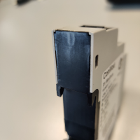
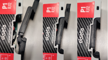
1. Remove the DIN Rail Cover:
- Locate the small tabs on both sides of the black DIN rail cover.
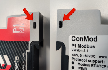
- Using a flathead screwdriver or your fingers, gently pry the tabs to release the cover. Work on one side at a time.
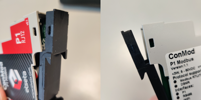
- Remove the DIN rail cover from the housing by pulling up from where it is opened.
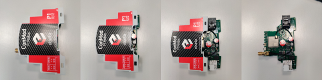
2. Slide Out the PCB:
- Make sure that antenna cap is off and there are no connectors attached on the P1
- From the front of the device, press the Wi-Fi antenna connector inward.
- While doing this, slide the PCB forward until it is completely out of the case.
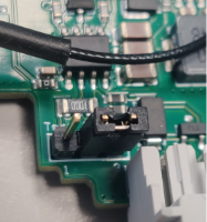
3. Locate the Terminating Resistor Pins:
- On the PCB, find the 3-pin header labeled “TERM EN/DIS”.
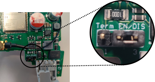
- There is a small jumper positioned across two of the pins.
4. Adjust the Terminating Resistor:
- By default, the jumper is set to Disable termination.
- To Enable, remove the jumper from its current position and place it on the alternate pair of pins as indicated by the “TERM EN/DIS” marking on the PCB
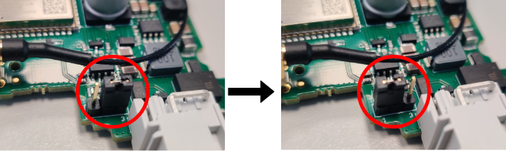
- Ensure the jumper is fully seated in the desired position.
5. Reassemble the Device:
- Slide the PCB back into the case, until the antenna connector properly protrudes through the front housing.

- Confirm the Wi-Fi antenna connector is correctly positioned outside the case.
- Slide in the din rail cover in reverse order and gently press tabs in.
6. Final Check:
- Verify that the DIN rail cover is securely attached.