IOMOD 8DI4RO User Manual Modbus
Introduction
IOMod 8DI4RO is a small-size stand-alone Modbus RTU, IEC 60870-5-103 or IEC-60870-5-101 digital input and relay output controller (protocol depends on firmware). IOmod can be used for industrial applications, where digital signaling is used and robust communication is needed. IOmod is an ideal solution for applications such as data acquisition, control, and process monitoring at remote places. This user manual is written for Modbus protocol firmware version.
Features
-
8 digital inputs;
-
Configurable active input signal polarity or input inversion;
-
4 relay outputs;
-
Galvanically isolated inputs and outputs;
-
Pulsed or latched mode for individual outputs;
-
Possible output feedback measurement with inputs;
-
Configuration over USB console or MODBUS RTU;
-
Values with data and time information;
-
Drag and Drop firmware upgrade over USB mass storage;
-
Modbus RTU, IEC-60870-5-103, IEC-60870-5-101 communication over RS485;
- Software selectable RT 120 Ohm termination resistor on RS485 interface;
-
LED indication for input/output and data transmission;
-
Easy integration with WCC Lite gateway and CloudIndustries.eu platform;
Operational information
IOmod 8DI4RO uses Modbus RTU, IEC 60870-5-103, or IEC 60870-5-101 protocol to communicate with a master device over RS485 interface. Protocol used by the device can be changed by uploading the corresponding firmware.
Status LED
Status LED can be in 2 colors :
Blue - Device connected to USB.
Green - Normal operation.
Rx/Tx LED
The RX/TX LED on the IOMod flashes when data is either being transmitted or received via the RS485 port.
MODBUS operational information
To read output status, send 01 Modbus command (Read Coils) with address of the first register (0) and displacement of 4. Returned value will show all 4 output states (1 - turned On, 0 - turned Off).
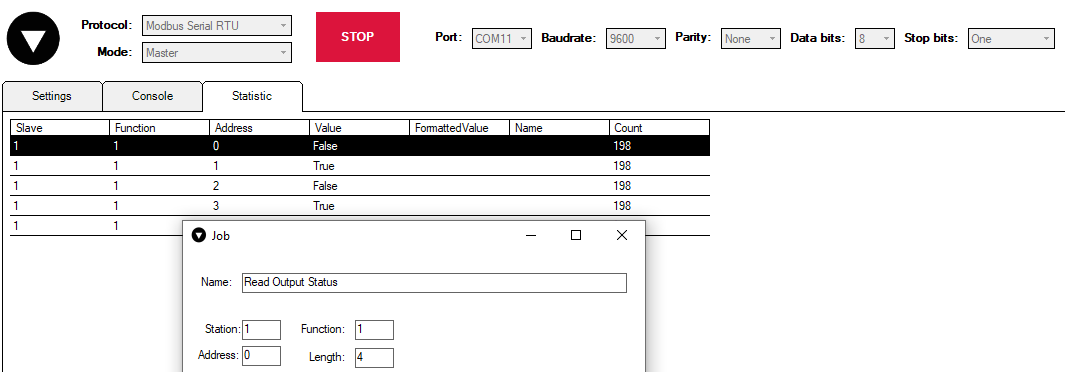
The fourth byte in 8DI4RO respond shows the status of outputs (0A = 0000 1010, means that RO2 and RO4 outputs are turned on).

To read input status, send 02 Modbus command (Read Discrete Inputs) with address of first register (0), and displacement of 8. Returned value will show 8 input states.
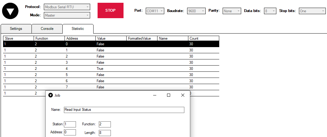
The fourth byte in 8DI4RO respond shows the status of outputs (10 = 0001 0000, means that fifth input is turned on).

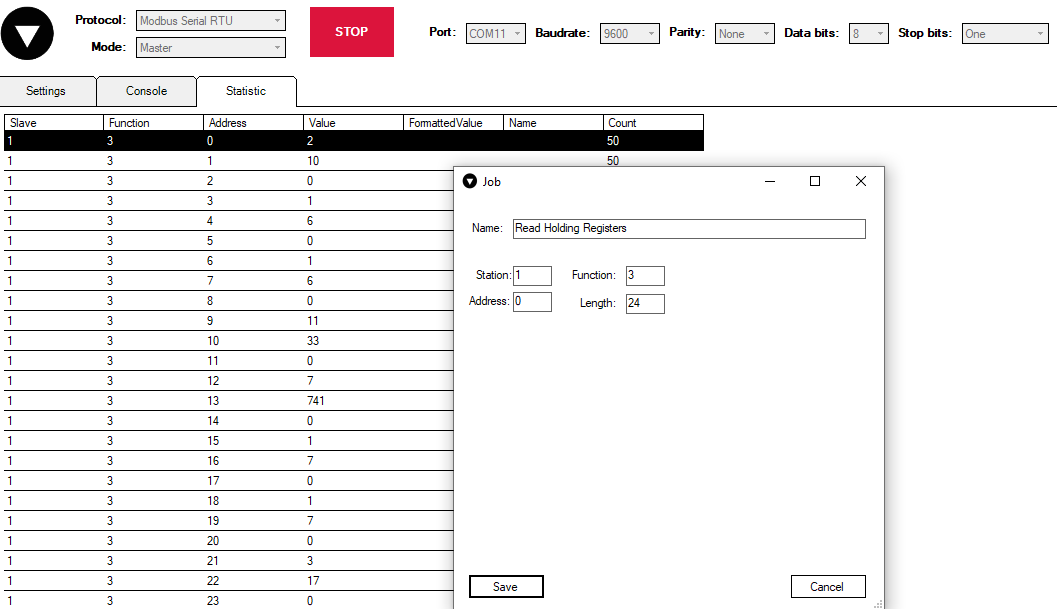
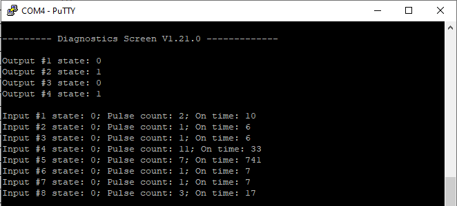
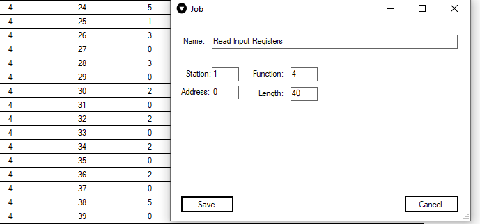
To read input counter values, send 03 Modbus command (Read Holding Registers) or 04 Modbus command (Read Input Registers) with resolution of first register (0) and size of 24. Returned data will show pulse count (first register) and ON time (2nd and 3rd registers) for each input – pulse count of input #2 will be at register 4th, and so on. ON time will be shown as seconds.
Function 3:
Function 4:
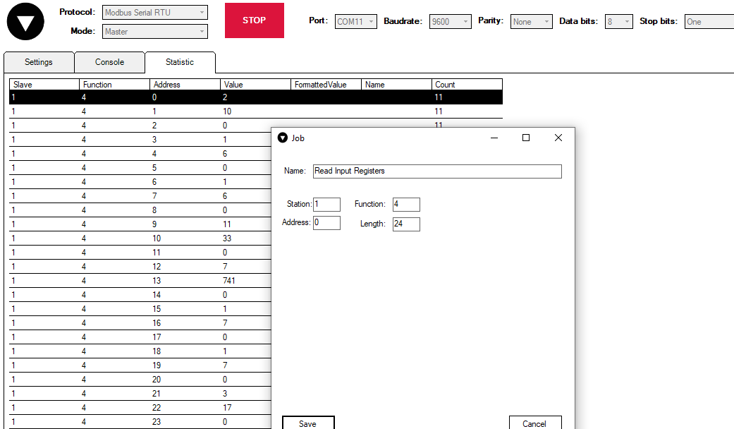
Values can be compared with values in Diagnostics Screen in Putty application (this interface will be discussed later):
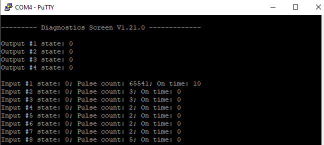
ON time and pulse count will increase when input pulse is longer than Filter time, which is configured by user in USB terminal menu. Shorter pulses will be ignored in both pulse and ON time registers. From software version 1.10, as capacity of input counter expanded to 32-bits, additional 16 registers depict such wider values in registers 00023-00039. That means that function 3 and 4 commands can be sent with length 40 specified. Then 24-39 registers are going to display only pulse count values:
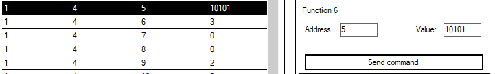
Two registers are allocated for each pulse count value. If value of pulse count becomes more than 65535 then second register comes into use. The values above can be compared with values from diagnostics screen:
These input counter values can be changed by using 06 Modbus command.

To turn single output on or off, send command 05 (Write Single Coil), with output address (0 to 3). To turn output on – send hex value FF00; to turn off – hex value 0000.
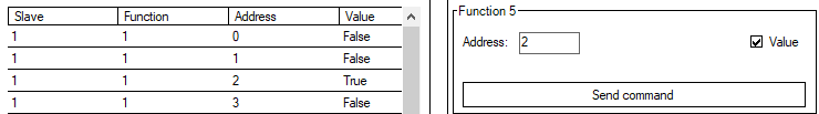

To turn multiple outputs on or off, use command 15 (Write Multiple Coils), and send binary coded value for 4 coils at address (0) and length 4.
To invert input states by software configure device over USB terminal. Useable Modbus commands shown in table below.
Supported MODBUS functions
01 (0x01) Read Coil Status
Reads status of relays (Off or On). IOMOD 8DI4RO has 4 relay outputs from address 0 to address 3.
02 (0x02) Read Discrete Inputs
Reads status of digital inputs (Off or On). IOMOD 8DI4RO has 8 digital inputs from address 0 to address 7. These inputs are active-high by default.
03 (0x03) Read Holding Registers
Lets user read counter/timer values dedicated to digital inputs. There are 40 MODBUS registers. Values held in these registers are explained in a table below. There are two types of values - Pulse Counter and On Timer, the latter calculating the time that respective input was held in its active state.
04 (0x04) Read Input Registers
Lets user read counter/timer values dedicated to digital inputs. There are 80 MODBUS registers. Values held in these registers are explained in a table below. There are two types of values - Pulse Counter and On Timer, the latter calculating the time in seconds that respective input was held in its active state. This function is deprecated and mirrors function 0x03 to conform to past versions of IOMOD 16DI.
05 (0x05) Write Single Coil
Sets a single relay output On or Off. Output addresses from 0 to 3 (first output – address 0, last output – address 3).
06 (0x06) Preset Single Register
Sets a single register. Register addresses is identical to “Read Input Registers” addresses.
15 (0x0F) Write Multiple Coils
Sets multiple relay output On or Off. Output addresses from 0 to 3 (first output – address 0, last output – address 3).
Modbus register mapping table
| Register | Description | Value range |
| Read coil status (01) | ||
| 00000-00007 | Reading digital outputs RO1-RO4 |
0-255 |
| Read discrete inputs (02) | ||
| 00000-00007 | Reading digital inputs DI1-DI8 |
0-255 |
| Read holding register (03), Read input register (04), Preset Single Register (06) | ||
| 00000 | Pulse count for DI1, Least Significant Word |
0-65535 |
| 00001-00002 | On-time in seconds for DI1, Least Significant Word first* | 0-65535 |
| ... | ... | ... |
| 00021 | Pulse count for DI8, Least Significant Word | 0-65535 |
| 00022-00023 | On-time in seconds for DI8, Least Significant Word first* | 0-65535 |
| 00024-00039 | Pulse count for DI1-DI8, Least Significant Word first* | 0-65535 |
| Write single coil (05) | ||
| 00000-00003 | Writing a single relay output | 0x0000 / 0xFF00 |
| Write multiple coils (15) | ||
| 00000-00003 | Writing multiple relay outputs RO1-RO4 | 0-255 |
*It is advised to set most significant word of counter/timer first
Device configuration
Input inversion and polarity selection
Unlike 8DI8DO IOmod 8DI4RO does not have pull-up resistors. If user desires to turn input status on, when that input signal is low, user then inverts inputs logically. All input indication LED’s stay the same (are not inverted).
Input / Output grouping
Sometimes two inputs or two outputs must be captured as one DPI input or output. Inputs and outputs can be grouped into the pairs of two. This allows outputs to be controlled by one DPI command (of address of first output in the group). Only two neighbor pins can be grouped into pair, while first pin in pair must be an odd number pin. When grouped, second pin in the pair is not used anymore – all requests for this pin generate an error. For example – RO1.1-2 and RO2.1-2 can be grouped, after that RO2.1-2 is not used; RO2.1-2 and RO3.1-2 cannot be grouped; RO3.1-2 and RO4.1-2 can be grouped, but RO4.1-2 is not used then, etc.
Fig. 1. picture shows outputs and inputs ungrouped and controlled independently. In this mode, General Interrogation will be composed of 4 output states and 8 input states.
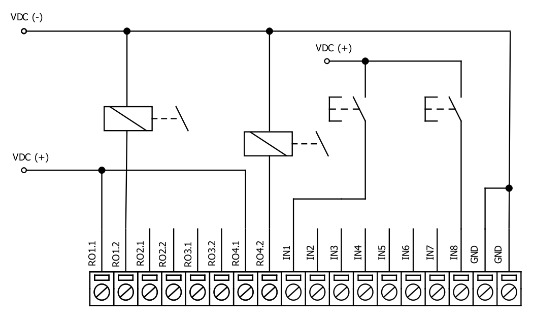
Fig. 1.
Let's consider a situation shown in Fig. 2. In the picture below first two relay outputs are grouped into pair. Also 3rd and 4th inputs are grouped into pair. Now, General interrogation will be composed of 3 output states (with RO2.1-2 missing), and 7 input states (with IN4 missing). Output and input numbers is represented by “Info number” in protocol.
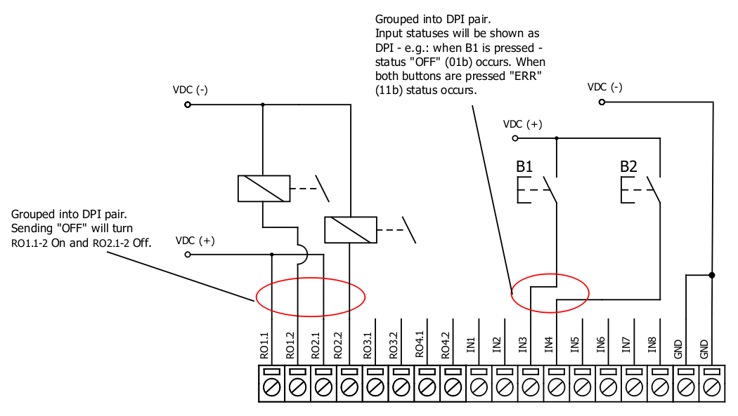
Fig. 2.
Input filter
Input filter is a simple glitch filter with time input. This filter time corresponds to stable time that input must achieve before sending a status change.
Output pulse time
User can configure outputs to be pulse controlled – it means that output will be turned on for configured amount of time. When this time runs out, output is turned off. This is useful when pulse toggle relays are used. Output pulse is independent from output grouping option and can be used on both grouped and ungrouped outputs. When output is grouped, device will allow only one command completion at a time – when output is already turned ON, other “turn ON” requests will be responded with NACK. If user desires latching outputs to be used, output pulse time is set to 0.
In the picture below is depicted an example of pulse output usage. Inputs and outputs are grouped, and output pulse time is set to 1s. When user sends ON command, RO2.1-2 are pulsed for 1s, and relay is set. This will connect NO contact and IN2 will turn on (assuming it is not inverted). When user sends OFF command, RO1.1-2 are pulsed, and relay is reset, turning IN1 on.
Output detection with inputs
Users can detect an output change with inputs.
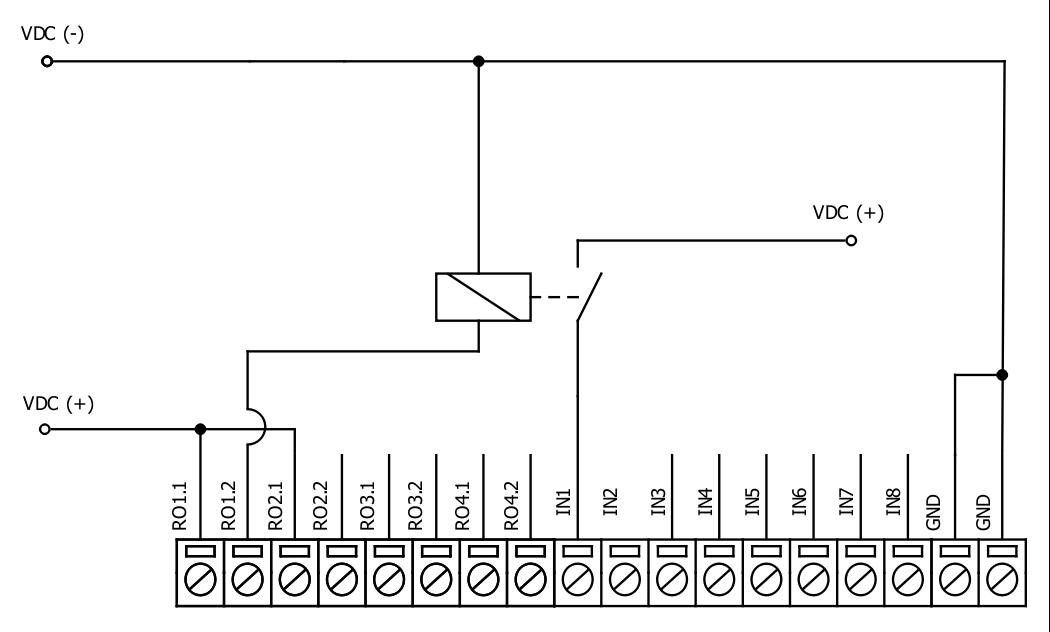
Fig. 3.
To find out if relays are turned on, user can connect relay outputs to IOmod inputs (maximum allowed voltage must be taken into account). When relays are turned on, device responds with IEC-60870-5-101 protocol message “Remote Operation”. If inputs are never turned on or off, device will send “Remote Operation” message after time-out period, with current input statuses. Time-out period is configured by user as a Feedback Time.
Technical information
|
|
System |
|
|
1. |
Dimensions |
101 x 119 x 22.5 mm |
| 2. |
Case |
IP20, blend PC/ABS self-extinguishing, black |
|
3. |
Working environment |
Indoors |
|
4. |
Operating temperature |
from -30°C to +70°C |
|
5. |
Humidity |
5-95% RH (non-condensing) |
|
6. |
Configuration |
USB – serial console, MODBUS RTU |
|
7. |
Firmware upgrade |
USB – mass storage device |
|
|
Electrical specifications |
|
|
|
Inputs |
|
|
8. |
Nominal input voltage range |
12-48VDC |
|
9. |
Isolation |
8 X 3kV(rms) |
|
10. |
Maximum input voltage |
60VDC |
|
|
Output relay contacts ratings |
|
|
11. |
Isolation |
4 X 3kV(rms) |
|
12. |
Rated resistive load |
5 A (at 250 VAC or at 30 VDC) |
|
13. |
Rated inductive (L/R=7ms) load |
2 A (at 250 VAC or at 30 VDC) |
|
14. |
Maximum switching voltage |
277 VAC 125 VDC |
|
15. |
Maximum switching current |
5 A |
|
|
Power |
|
|
16. |
Power Supply |
12-24 VDC / 9-33 VDC (full range) |
|
17. |
Current consumption |
70 mA |
In the Fig. 5. you can see internal structure of 8DI4RO IOmod. An important fact to metion is that as it can be noticed in the scheme below all inputs are isolated. However ground connection is common for all phototransistors.
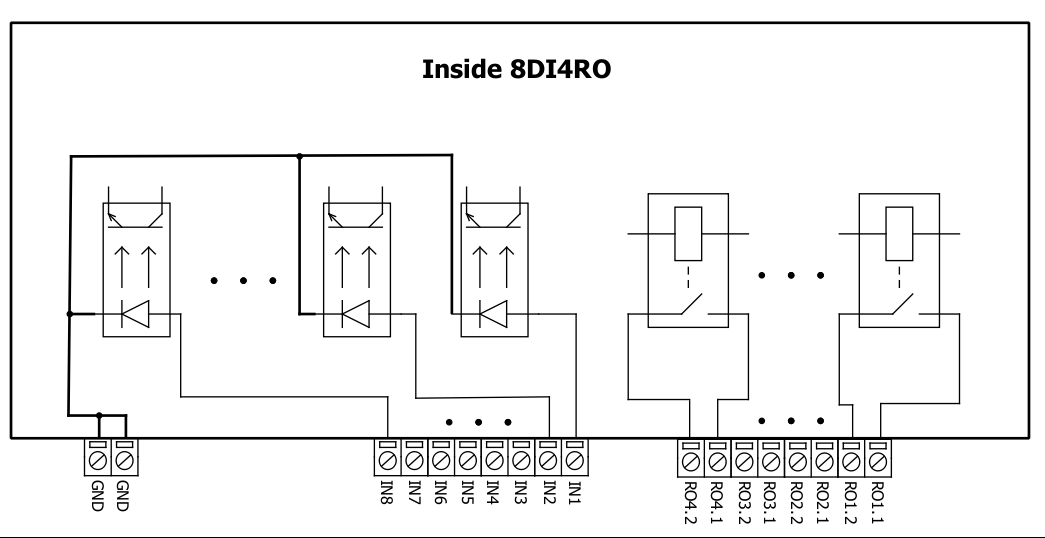
Fig. 4.
Mounting and installation guide
IOmod 8DI4RO RS485 interface
IOmod 8DI4RO has an integrated 120Ω termination resistor which can be enabled or disabled over USB configuration. It is recommended to use termination at each end of the RS485 cable. See typical connection diagram on Fig. 6.
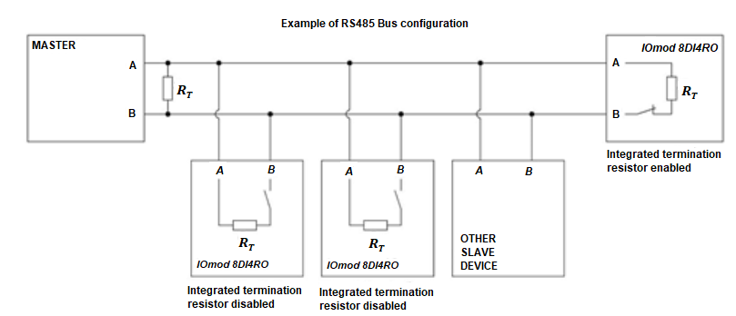
Fig. 5.
IOmod 8DI4RO has 1/8 Unit load receiver which allows to have up to 256 units on line (compared to standard 32 units). To reduce reflections, keep the stubs (cable distance from main RS485 bus line) as short as possible when connecting device.
IOmod 8DI4RO inputs
Typical application of IOmod 8DI4RO inputs is shown on Fig. 2. When default configuration for inputs is applied, user will see inputs connected to +12-24V as “high” or state “1” and input status LED will glow.
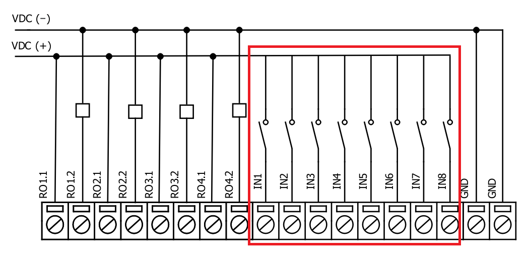
Fig. 6.
User also can configure to enable software input inversion. With this configuration, user will see inputs connected to 0V (see Fig. 3.) as “high” or state “1”, input status LED will NOT glow.
IOmod 8DI4RO outputs
IOmod 8DI4RO has 4 relay outputs. Internal clamp diodes are connected to each output which makes IOmod 8DI4RO ideal for driving inductive loads like relays. Maximum 5A per output is allowed. For higher loads outputs can be connected in parallel. Make sure your power supply can provide enough power. Typical application of outputs is shown on Fig. 4.
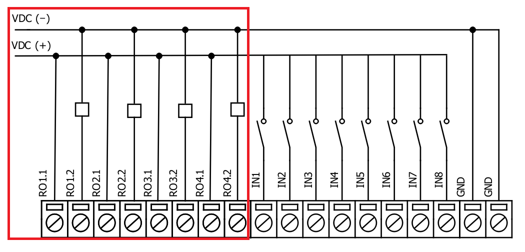
Fig. 7.
Configuration over USB
Driver installation
Device requires USB drivers to work as a Virtual COM port. First-time connection between device and computer could result in “Device driver software was not successfully installed” error (Fig. 5.).
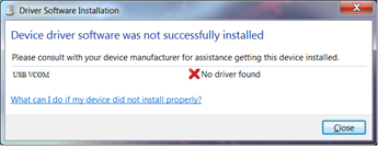
Fig. 8.
Drivers can be installed from Wiki Esleseta -> Downloads -> IOMOD Series Downloads-> Firmware and tools -> IOMOD USB drives for Windows;
User then manually installs drivers by selecting downloaded driver folder:
Go to Control Panel -> Hardware and Sound -> Device Manager
Select failed device;
Press “Update driver software”; screen in Fig. 6. should appear:
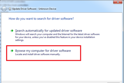
Fig. 9.
Select “x86” driver for 32-bit machine, or x64 for 64-bit machine. If not sure, select root ("vcom") folder (folder in which x64 and x86 lays inside).
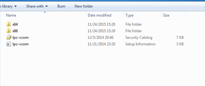
Fig. 10.
IOmod configuration with PuTTY terminal
Configuration of IOmod device is done through CLI (Command Line Interface) on a virtual COM port. Drivers needed for MS Windows to install VCOM will be provided. To open up CLI simply connect to specific V-COM port with terminal software (it is advised to use PuTTY terminal software. If other software is being used, user might need to send <return> symbol after each command). When connected user should immediately see main screen. Accidental close of the terminal window does not stop USB connection, user can connect terminal program again, and press any key on keyboard to show up main menu again.
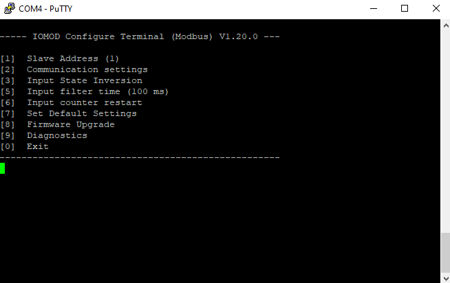
Fig. 11.
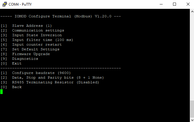
Fig. 12.
Main Menu
|
Menu Name |
Function |
Values |
Default Values |
|
| 1. |
Slave Address |
Modbus Slave address / ID |
1-254 |
1 |
| 2. |
Communication settings |
Enters configuring screen for communication settings. |
- |
- |
| 2.1 |
Configure baudrate |
Configure number of bits transmitted per second |
100 - 256 000 |
9600 |
| 2.2 |
Data, Stop and Parity bits |
Configure length and content of packets |
[1] 8+1 [2] 8+2 Parity: [1] None [2] Odd [3] Even [4] Mark [5] Space |
8+1+N |
| 2.3 |
RS485 Terminating Resistor |
RS485 120 Ohms Terminating Resistor |
[1] Enable [2] Disable |
Disabled |
| 3. |
Input State Inversion |
Input state inversion for individual pins. Inverts states of input signals, so that high input voltage is considered to be logical 0 and vice versa. |
[1] Inverted [2] Set Normal |
Normal |
| 4. |
Input filter time |
Filter for short input pulses |
0 - 256 000 (ms) |
100 |
| 5. |
Input counter restart |
Restarts all input counter registers to 0 |
[1] Confirm [0] Cancel |
- |
| 6. |
Set Default Settings |
Sets Default Settings |
[1] Confirm [0] Cancel |
- |
| 7. |
Firmware Upgrade |
Mass Storage Device Firmware Upgrade |
[1] Confirm [0] Cancel |
- |
| 8. |
Diagnostics |
Input / Output states |
- |
- |
| 0. |
Exit |
Exit and disconnect |
- |
- |
Protocol simulator
When entered diagnostics screen, user can turn on USB protocol simulator mode by pressing [9]. When protocol simulator is turned on, device will communicate through USB port rather than RS-485 line. Communication on RS-485 line is closed and all IEC-101 commands will be accepted only from USB. To exit this mode user must restart device.
Firmware upgrade over USB
To update device firmware user must enter main configuration menu and enter Firmware upgrade screen by pressing [8] is shown in Fig. 13.
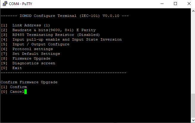
Fig. 17.
Confirm upgrade by pressing [1];
Device should enter a Firmware Upgrade mode. It means that device switches from USB Console mode into Mass storage device and computer recognize it as USB Storage.
Usually after confirming the upgrade a window with an error message appears (Fig. 14)

Fig. 18.
User then must delete existing file “firmware.bin”, and simply drag and drop new firmware file.
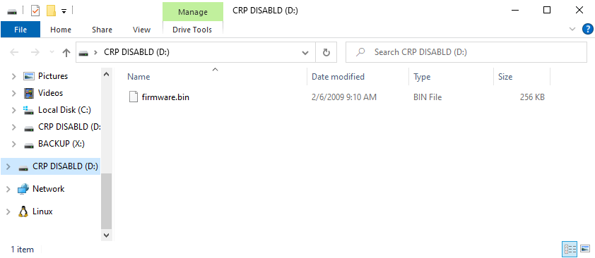
Fig. 19.
Finally, reconnect device and check firmware version. Lastly, you may want to set default settings by pressing [7].