ConMod User Manual 1.0.2
Overview
ConMod P1Modbus is a small industrial protocol converter for smart Meters with P1 interface output to convert meter data into industrial standard protocols Modbus RTU and Modbus TCP with interfaces RS485 and Wi-Fi (2,4GHz).
They are designed to convert smart meter data into the most popular industrial protocol – Modbus. The solution perfectly fits integration with energy management systems, remote monitoring, SCADA systems, etc.
ConMod P1Modbus is compatible with the DSMR interface and supports different versions and variations of data formats. Also, ConMod P1Modbus has a menu to show RAW data (P1 telegram) collected from the smart meter to enable comparison with converted data in Modbus registers.
ConMod P1Modbus is designed for industrial applications with cybersecurity in mind to disable Wi-Fi communication and avoid illegal communication over Wi-Fi in critical infrastructure projects.
Features
- Easy configuration using Wi-Fi via mobile phone or a laptop;
- Indication about P1 interface, RS485, and Wi-Fi data on built-in LED’s;
- Both Modbus RTU and Modbus TCP are available at the same time;
- Debug information about P1 telegram available with every data frame from Smart Meter;
- Support different meters with DSMR interfaces like SAGEMCOM and others;
- Easy to change Modbus Slave ID and serial communication speed;
- Built-in switchable terminating resistors for RS485;
- Possibility to provide power for protocol converter from P1 interface as well from external power supply;
- Wide power supply range from 5V to 60VDC;
- External Wi-Fi antenna with SMA connector;
- Wi-Fi on/off switch;
- Reset the device button;
- Communication port RS485, Wi-Fi (2,4GHz B/G/N);
- Modbus RTU, Modbus TCP protocols.
Connection
It is highly recommended that the RJ12 wire is not longer than 7 meters, otherwise the connection might be unstable.
To connect ConMod to a meter, an RJ12 cable is required. As shown in the picture below, one side of the cable is connected to a ConMod P1 port, and the other one to a meter. After connecting P1 LED will light up. Instructions on how to connect to a Wi-Fi are described below in the paragraph Connection and Configuration over Wi-Fi.
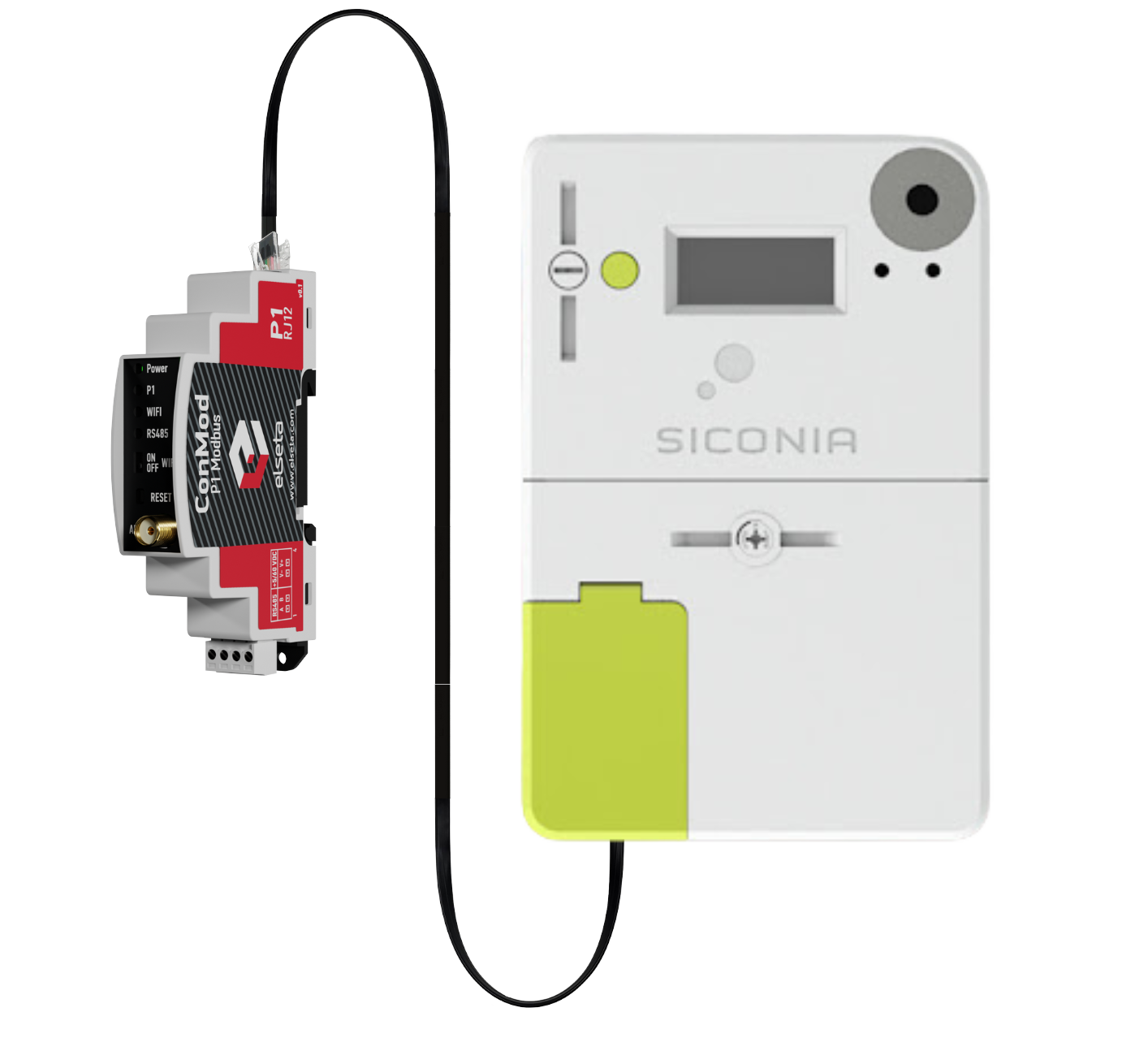
Fig. 1. P1 connection to a smart meter via RJ12 cable
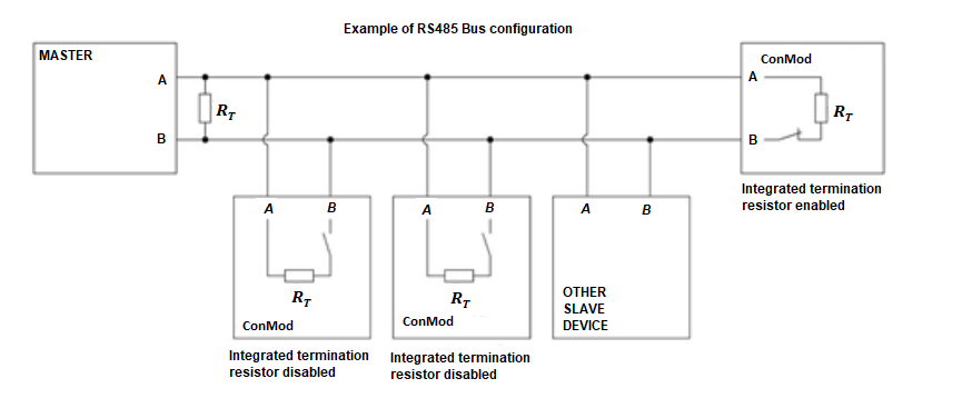
Fig.2. RS485 Bus configuration
Common configuration information
ConMod receives data from meters via the P1 interface and sends data back via Modbus protocol using function 3 (read holding registers). Default serial communication parameters are:
| slave id | 1 |
| Baud rate | 9600 |
| data bits | 8 |
| stop bits | 1 |
| parity | none |
There is a list of signals and their Modbus registers in the table below. The names of the registers might differ.
| Name | Units | Modbus register | Length |
Number type |
| serial number | - | 1 | 4 | UNSIGNED64 |
| correct data counter | - | 5 | 1 | UNSIGNED16 |
| faulty data counter | - | 6 | 1 | UNSIGNED16 |
| device error | - | 7 | 1 | UNSIGNED16 |
| Active energy import (+A) | Wh | 8 | 2 | UNSIGNED32 |
| Reactive energy import (+R) (QI+QII) | varh | 10 | 2 | UNSIGNED32 |
| Reactive energy export (-R) (QIII+QIV) | varh | 12 | 2 | UNSIGNED32 |
| Active energy import (+A) rate 1 | Wh | 14 | 2 | UNSIGNED32 |
| Active energy import (+A) rate 2 | - | 16 | 2 | UNSIGNED32 |
| Active energy import (+A) rate 3 | Wh | 18 | 2 | UNSIGNED32 |
| Active energy import (+A) rate 4 | Wh | 20 | 2 | UNSIGNED32 |
| Active energy export (−A) rate 1 | Wh | 22 | 2 | UNSIGNED32 |
| Active energy export (−A) rate 2 | Wh | 24 | 2 | UNSIGNED32 |
| Active energy export (−A) rate 3 | Wh | 26 | 2 | UNSIGNED32 |
| Active energy export (−A) rate 4 | Wh | 28 | 2 | UNSIGNED32 |
| Reactive energy (+R) rate 1 | varh | 30 | 2 | UNSIGNED32 |
| Reactive energy (+R) rate 2 | varh | 32 | 2 | UNSIGNED32 |
| Reactive energy (+R) rate 3 | varh | 34 | 2 | UNSIGNED32 |
| Reactive energy (+R) rate 4 | varh | 36 | 2 | UNSIGNED32 |
| Reactive energy (-R) rate 1 | varh | 38 | 2 | UNSIGNED32 |
| Reactive energy (-R) rate 2 | varh | 40 | 2 | UNSIGNED32 |
| Reactive energy (-R) rate 3 | varh | 42 | 2 | UNSIGNED32 |
| Reactive energy (-R) rate 4 | varh | 44 | 2 | UNSIGNED32 |
| Instantaneous voltage L1 | V | 46 | 2 | UNSIGNED32 |
| Average voltage L1 | V | 48 | 2 | UNSIGNED32 |
| Instantaneous current L1 | A | 50 | 2 | UNSIGNED32 |
| Sliding Average current L1 (for fuse supervision) | A | 52 | 2 | UNSIGNED32 |
| Instantaneous voltage L2 | V | 54 | 2 | UNSIGNED32 |
| Average voltage L2 | V | 56 | 2 | UNSIGNED32 |
| Instantaneous current L2 | A | 58 | 2 | UNSIGNED32 |
| Sliding Average current L2 (for fuse supervision) | A | 60 | 2 | UNSIGNED32 |
| Instantaneous voltage L3 | V | 62 | 2 | UNSIGNED32 |
| Average voltage L3 | V | 64 | 2 | UNSIGNED32 |
| Instantaneous current L3 | A | 66 | 2 | UNSIGNED32 |
| Sliding Average current L3 (for fuse supervision) | A | 68 | 2 | UNSIGNED32 |
| Instantaneous voltage (U) [V] | V | 70 | 2 | UNSIGNED32 |
| Instantaneous current [A] | A | 72 | 2 | UNSIGNED32 |
| Instantaneous current in neutral [A] | A | 74 | 2 | UNSIGNED32 |
| Instantaneous current (sum over all phases) | A | 76 | 2 | UNSIGNED32 |
| Instantaneous net frequency; any phase | Hz | 78 | 2 | UNSIGNED32 |
| Instantaneous active power (|+A|+|-A|) | W | 80 | 2 | UNSIGNED32 |
| Instantaneous active import power (+A) in phase L1 [kW] | W | 82 | 2 | UNSIGNED32 |
| Instantaneous active import power (+A) in phase L2 [kW] | W | 84 | 2 | UNSIGNED32 |
| Instantaneous active import power (+A) in phase L3 [kW] | W | 86 | 2 | UNSIGNED32 |
| Instantaneous active export power (-A) in phase L1 [kW] | W | 88 | 2 | UNSIGNED32 |
| Instantaneous active export power (-A) in phase L2 [kW] | W | 90 | 2 | UNSIGNED32 |
| Instantaneous active export power (-A) in phase L3 [kW] | W | 92 | 2 | UNSIGNED32 |
| Instantaneous reactive import power (+R) in phase L1 [kvar] | var | 94 | 2 | UNSIGNED32 |
| Instantaneous reactive import power (+R) in phase L2 [kvar] | var | 96 | 2 | UNSIGNED32 |
| Instantaneous reactive import power (+R) in phase L3 [kvar] | var | 98 | 2 | UNSIGNED32 |
| Instantaneous reactive export power (-R) in phase L1 [kvar] | var | 100 | 2 | UNSIGNED32 |
| Instantaneous reactive export power (-R) in phase L2 [kvar] | var | 102 | 2 | UNSIGNED32 |
| Instantaneous reactive export power (-R) in phase L3 [kvar] | var | 104 | 2 | UNSIGNED32 |
| Instantaneous apparent import power (+VA) | VA | 106 | 2 | UNSIGNED32 |
| Instantaneous apparent import power (+VA) in phase L1 | VA | 108 | 2 | UNSIGNED32 |
| Instantaneous apparent import power (+VA) in phase L2 | VA | 110 | 2 | UNSIGNED32 |
| Instantaneous apparent import power (+VA) in phase L3 | VA | 112 | 2 | UNSIGNED32 |
| Instantaneous apparent export power (-VA) | VA | 114 | 2 | UNSIGNED32 |
| Instantaneous apparent export power (-VA) in phase L1 | VA | 116 | 2 | UNSIGNED32 |
| Instantaneous apparent export power (-VA) in phase L2 | VA | 118 | 2 | UNSIGNED32 |
| Instantaneous apparent export power (-VA) in phase L3 | VA | 120 | 2 | UNSIGNED32 |
| Average Import Power (+A) | W | 122 | 2 | UNSIGNED32 |
| Average Net Power (|+A|-|-A|) | W | 124 | 2 | SIGNED32 |
| Average Total Power (|+A|+|-A|) | W | 126 | 2 | UNSIGNED32 |
| Instantaneous Power factor (+A/+VA) | - | 128 | 2 | SIGNED32 |
| Instantaneous power factor in phase L1 | - | 130 | 2 | SIGNED32 |
| Instantaneous power factor in phase L2 | - | 132 | 2 | SIGNED32 |
| Instantaneous power factor in phase L3 | - | 134 | 2 | SIGNED32 |
| Minimum Power factor (+A/+VA) | - | 136 | 2 | SIGNED32 |
| Measurement Period 3 for Instantaneous values | s | 138 | 2 | UNSIGNED32 |
| Demand Register 1 - Active energy import (+A) | W | 140 | 2 | UNSIGNED32 |
| Demand Register 2 - Active energy export (−A) | W | 142 | 2 | UNSIGNED32 |
| Demand Register 3 - Reactive energy import (+R) | var | 144 | 2 | UNSIGNED32 |
| Demand Register 4 - Reactive energy export (-R) | var | 146 | 2 | UNSIGNED32 |
| Demand Register 5 - Apparent energy import (+VA) | VA | 148 | 2 | UNSIGNED32 |
| Demand Register 6 - Apparent energy export (-VA) | VA | 150 | 2 | UNSIGNED32 |
| Last Average Demand Register 1 - Active energy import (+A) | W | 152 | 2 | UNSIGNED32 |
| Last Average Demand Register 2 - Active energy export (−A) | W | 154 | 2 | UNSIGNED32 |
| Last Average Demand Register 3 - Reactive energy import (+R) | var | 156 | 2 | UNSIGNED32 |
| Last Average Demand Register 4 - Reactive energy export (-R) | var | 158 | 2 | UNSIGNED32 |
| Last Average Demand Register 5 - Apparent energy import (+VA) | VA | 160 | 2 | UNSIGNED32 |
| Last Average Demand Register 6 - Apparent energy export (-VA) | VA | 162 | 2 | UNSIGNED32 |
| Duration of last voltage sag in phase L1 | s | 164 | 2 | UNSIGNED32 |
| Duration of last voltage sag in phase L2 | s | 166 | 2 | UNSIGNED32 |
| Duration of last voltage sag in phase L3 | s | 168 | 2 | UNSIGNED32 |
| Magnitude of last voltage sag in phase L1 | V | 170 | 2 | UNSIGNED32 |
| Magnitude of last voltage sag in phase L2 | V | 172 | 2 | UNSIGNED32 |
| Magnitude of last voltage sag in phase L3 | V | 174 | 2 | UNSIGNED32 |
| Duration of last voltage swell in phase L1 | s | 176 | 2 | UNSIGNED32 |
| Duration of last voltage swell in phase L2 | s | 178 | 2 | UNSIGNED32 |
| Duration of last voltage swell in phase L3 | s | 180 | 2 | UNSIGNED32 |
| Magnitude of last voltage swell in phase L1 | V | 182 | 2 | UNSIGNED32 |
| Magnitude of last voltage swell in phase L2 | V | 184 | 2 | UNSIGNED32 |
| Magnitude of last voltage swell in phase L3 | V | 186 | 2 | UNSIGNED32 |
The number type in the Modbus protocol allows users to read data in different formats. The number type and data from the meter must be compatible. For example, if it takes 16 bits to read data and the sign (+/-) is important, then the user should configure the Modbus register as SIGNED 16. For further explanation of how number type determines data value, see the table below:
| Name | Description | Range |
| SIGNED16 | 16-bit signed integer (1 word) | -32768...+32767 |
| UNSIGNED16 | 16-bit unsigned integer (1 word) | 0...65535 |
| SIGNED32 | 32-bit signed integer (2 words) | -2 147 483 648... + 2 147 483 647 |
| UNSIGNED32 | 32-bit unsigned integer (2 word) | 0... 4 294 967 295 |
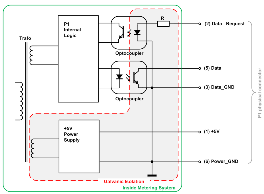
P1 connector circuit in meter
Technical information
| System | ||
| 1. | Dimension | 91 x 18 x 67 mm |
| 2. | Working temperature | -25°C | +55°C |
| 3. | Recommended operating conditions | -25°C | +55°C and >95 %RH (none condensing) |
| 4. | Configuration |
Web browser (Laptop and smartphone) |
| Electrical specifications |
||
| 5. | Functions |
|
| Power |
||
| 6. | Power Supply | 5V to 60V |
| 7. | Current consumption | <200mA @12 VDC |
LED status indication and control
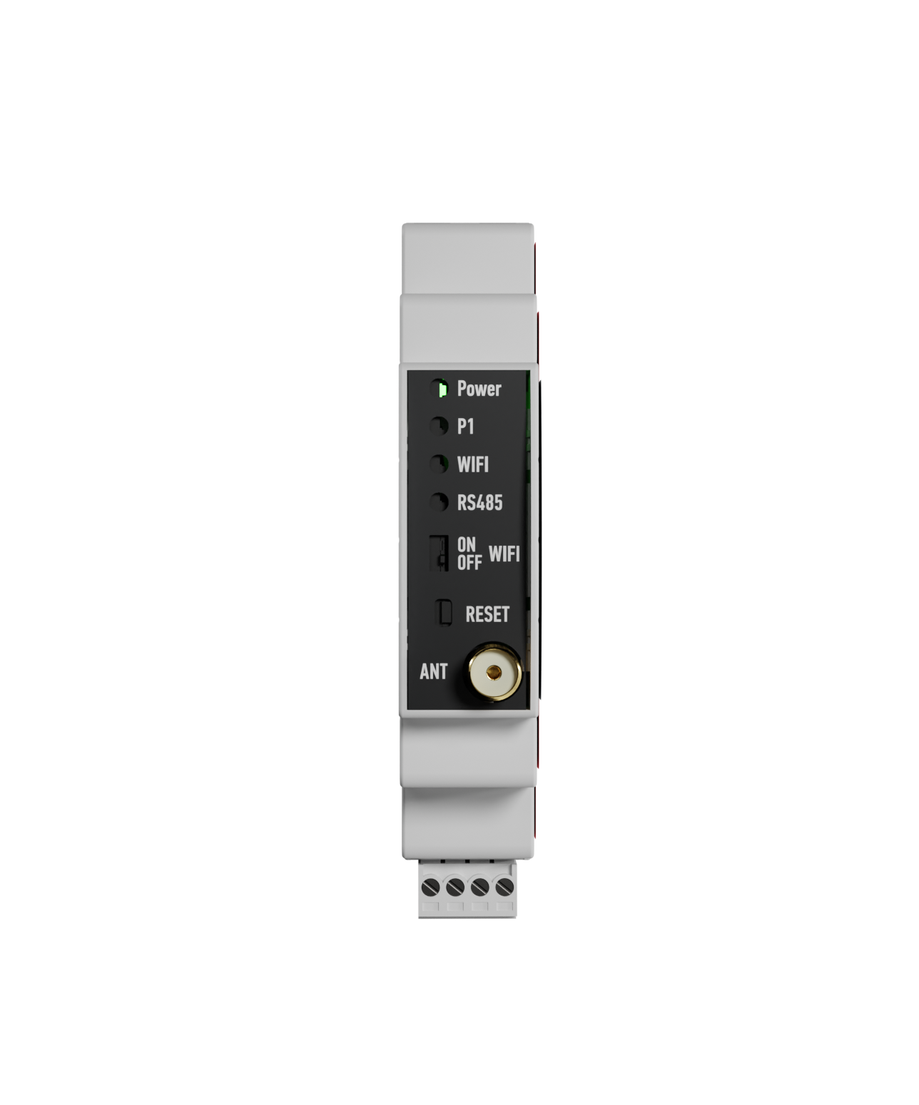
ConMod has LED indications for the P1 interface, RS485, Wi-Fi, a switch for enabling or disabling the Wi-Fi connection, and a reset button.
- The power LED turns green after connecting the ConMod to a power source.
- P1 LED turns on when ConMod receives a data packet from the meter.
- Wi-Fi LED indicates if the Wi-Fi connection is enabled. There is an ON/OFF switch to enable or disable Wi-Fi which can be seen below the LEDs.
- RS485 LED lights up when ConMod receives or sends data from another device via the RS485 interface. This could be either meter or WCC Lite.
By holding a reset button for ~5s, ConMod resets the Wi-Fi connection and allows it to connect to another network instead.
Connection and configuration over Wi-Fi
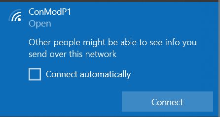
ConMod is compatible with meters that have a DSMR interface. After physically connecting the ConMod to the meter and turning it on, it becomes a Wi-Fi access point. To connect to ConMod click on Wi-Fi settings and connect to a new network – ConModP1:
Connection will redirect the user to the main configuration web page:
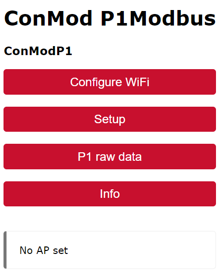
As seen in the image above, there is a message indicating that no AP (access point) is set. This means that the user will have to enter a password. To do so, simply click on Configure Wi-Fi, then select the Wi-Fi you are connecting to and enter the required credentials for this specific access point:
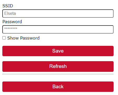
After entering the correct credentials click on save. If the password is correct, the connection will be established. This will be indicated with a message:

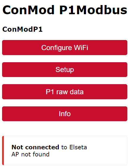
In case of an incorrect password, the message Not connected will appear (like in the picture below) and the connection to the ConModP1 network will be lost. In this case, the user should simply try to reconnect to the network and enter the correct credentials instead.
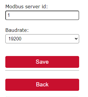
Another way to connect is via web address conmod.local but only after the connection is established. The user interface also allows to setup of Modbus parameters such as slave ID and baud rate:
There is also an option to read all the parameters from the meter without connecting ConMod to WCC Lite. Those parameters could also be found on the user interface by clicking on P1 raw data. It will show Obis codes and their corresponding values.