Tools and software
Here you will find all necessary tools to setup and configure IOmod devices.
USB Drivers
IOMod series devices has USB port for IO module configuration. Due to be accessible on some of Windows OS devices please find attached drivers.
IOmod-USB-driver-V-COM<- download link.
Configuration over USB
Driver installation
Device requires USB drivers to work as virtual com port. First-time connection between device and computer could result in “Device driver software was not successfully installed” error.
 Device driver error message
User then manually installs drivers by selecting downloaded driver folder:
Go to Control Panel -> Device Manager;
Select failed device;
Press “Update driver software”; following screen should appear.

Manually searching for device driversSelect “x86” driver for 32bit machine, or x64 for 64bit machine. If not sure, select root folder (folder in which x64 and x86 lays inside).

Uploading new firmware
Upload of firmware through USB to IOMod device is done through CLI (Command Line Interface) on virtual COM port. Drivers needed for MS Windows to install VCOM will be provided. To open up CLI simply connect to specific VCOM port with terminal software (it is advised to use PuTTY terminal software. If other software is being used, user might need to send <return> symbol after each command). When connected user should immediately see main screen similar to one in Fig. 1.
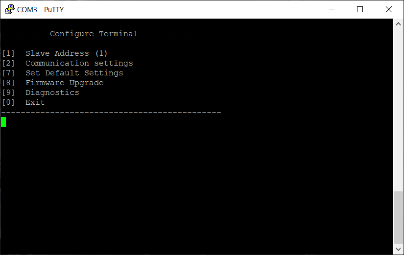 Fig. 1. PuTTY main screen.
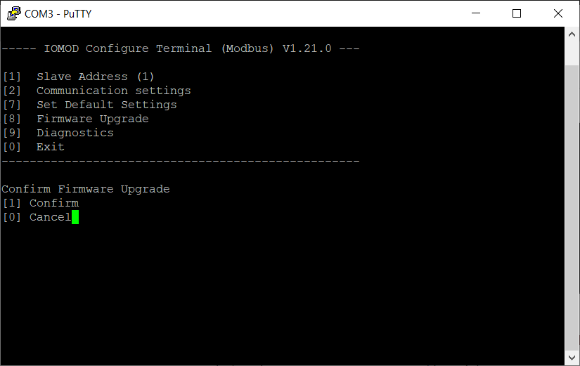 Fig. 2. Firmware upgrade confirmation screen.
User then must delete existing file “firmware.bin”, and simply upload new firmware file by drag and drop (in this example after deleting “firmware.bin” user must drag and drop one the prepared firmware files on the left to the folder on the right).
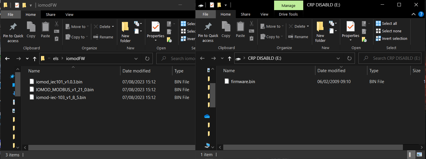 Fig. 3. Firmware ”iomodFW” folder and the folder to delete “firmware.bin” and upload one of the new firmware.
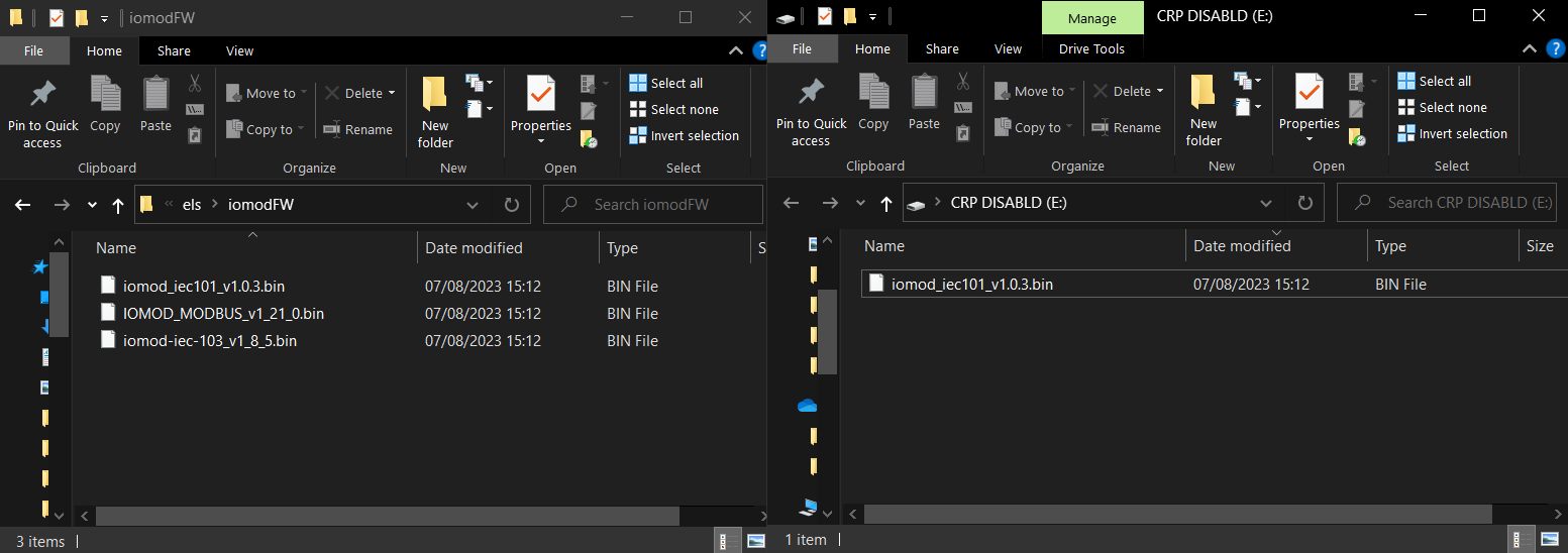 Fig. 4. Uploaded IEC-60870-5-101 firmware as an illustration.
After uploading the new firmware, user must exit the folder and dismiss the error caused by the firmware upgrade mode.
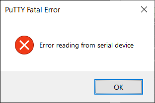 Fig. 5. Error caused by the upload.
Now the user must exit the PuTTY terminal software, and reinsert the USB cable.
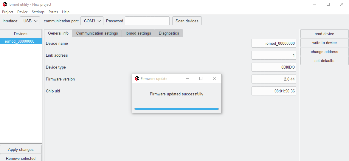
Reconnect the device and check firmware version. It should now represent the one it was updated to.
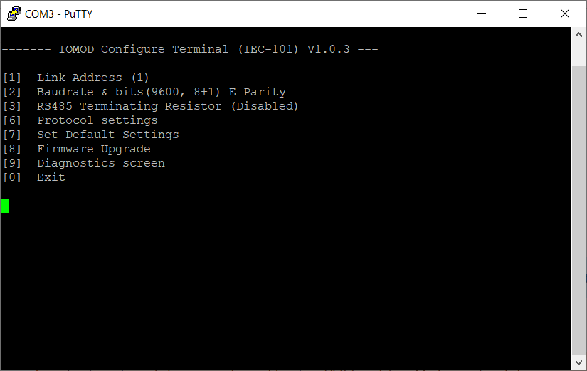 Fig. 6. Successful upload of new firmware.
Configuration of device is not possible when USB Simulation Mode is entered. To access configuration menu again user should reset device and then try again.
IOMOD Utility
IOMOD Utility
Overview
IOMOD Utility is a tool created to configure IOMODs with firmware version 2. This tool allows users to connect, configure, and diagnose IOMODs such as 8DI8DO, 8DI4RO, 16DI, 8AI, 4RTD, 4CS4VS, METER, and FPI. The Utility's interface allows users to connect to IOMOD via USB port, RS485, and ser2net.
The user can either configure devices online or offline. This means configuration is possible without directly connecting to IOMOD and can be done using templates. The templates allow the creation of configurations for one device or a whole set of IOMODs. By connecting IOMODs to a ser2net device, they can be configured remotely. This also includes firmware upgrades, configuration and diagnostics. More configuration information will be mentioned in the configuration chapter.
Each IOMOD is protected by a password. The default password is 20 empty bits and can be changed by the user. It is important to remember the new password after it is changed; otherwise, the IOMOD will not be configurable.
Software installation
The software can be downloaded from the IOMOD Utility download page. After downloading the .exe installation file run it. The setup will open.
- To install The IOMOD Utility accept the license agreement and click next.
- Select Installation Destination Location and click Next.
- Select Start Menu Folder and click Next.
- Choose whether to create a desktop shortcut.
- After the installation click finish, and the software will open automatically.
User Interface
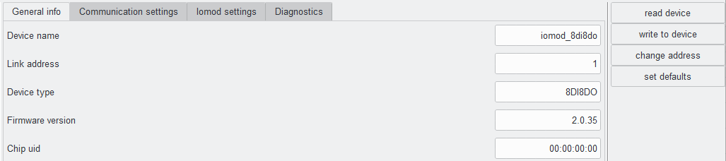
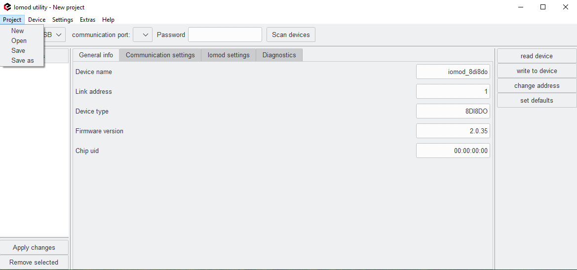
IOMOD Utility has four main tabs: General info, Communication settings, Iomod settings, and Diagnostics. The General info tab shows the main information about the device, letting the user differentiate which device is being configured. Users can change only the Device name and Link address. If the device's link address needs to be changed, first specify the address and click on the change address button. Any other changes will be executed by clicking the write to device button.
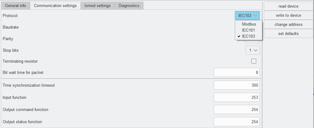
Communication settings have parameters for each protocol, which can be chosen in the drop-down menu. Each protocol has a different set of parameters, however, serial communication parameters are the same for all protocols. The default serial communication parameters are 19200 baudrate, Even (E) parity and 1 Stop bit. The user can set default settings for each protocol by clicking the set defaults button. The set default settings button will also set the protocol to IEC101.
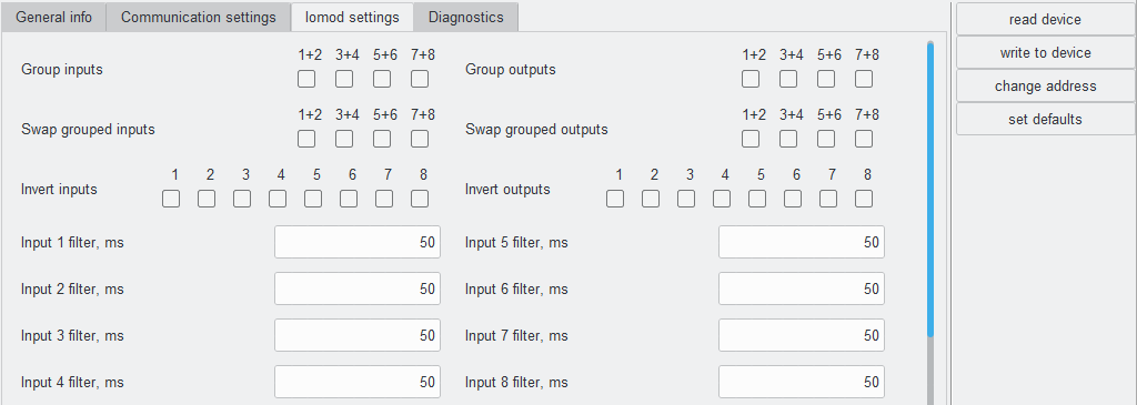
The Iomod settings tab is different for each IOMOD. On this tab, the user can configure the main parameters of the IOMOD. If no changes are made, default parameters will be displayed on this page. If the user needs to configure the device, after making the changes in this tab, click on the write to device button. If changes need to be reversed, the set defaults button will change it back. More information about each IOMOD configuration can be found in their manuals.
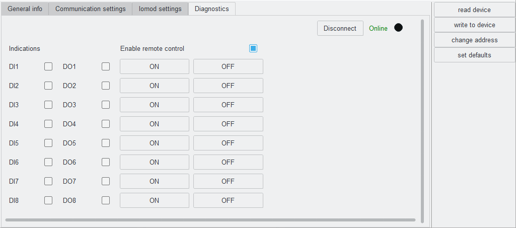
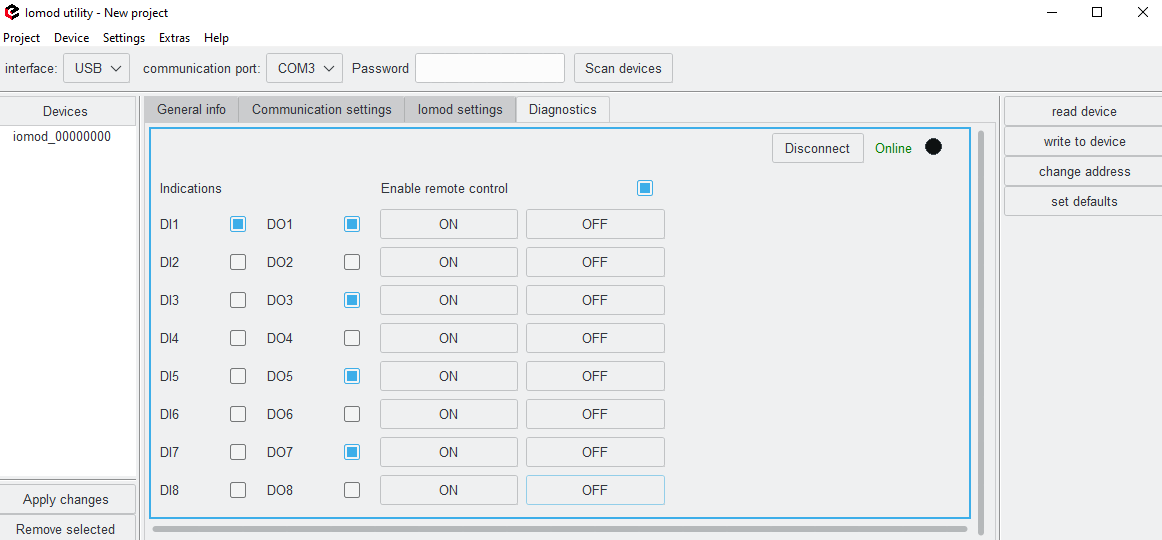
The Diagnostics screen shows real-time parameters of IOMOD, both analog and digital. The user can also activate outputs for IOMODs such as 8DI8DO and 8DI4RO. To do so the user should click Connect and then an Enable remote control check box.
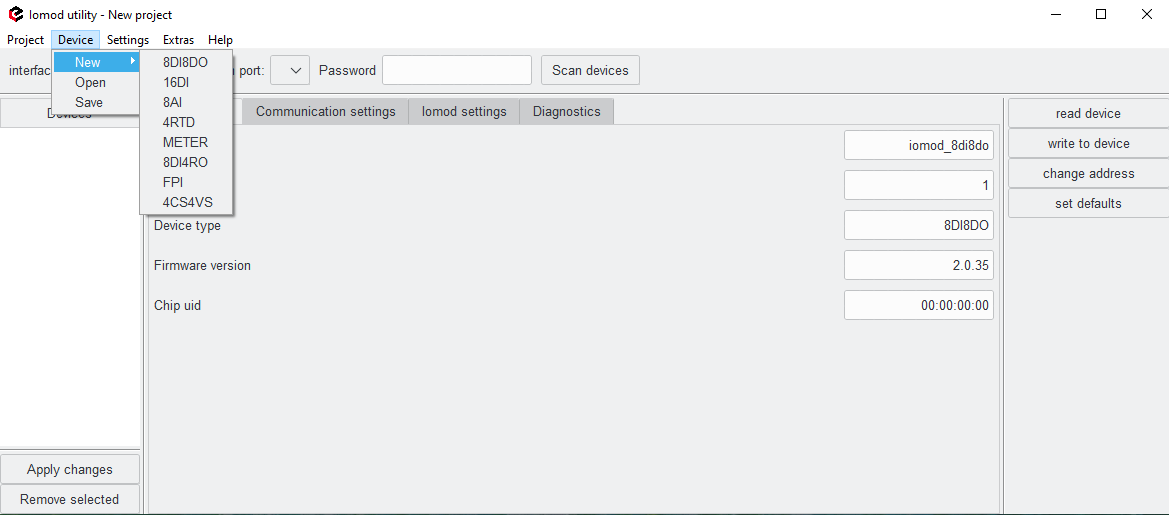
In the upper tools bar the user can find a Project button, which allows to control and create projects with multiple IOMODs. Project --> New creates a blank project and erases all changes made before. There is no need to click on Project --> New if the user opens the IOMOD Utility for the first time. Project --> open button opens an already saved project. To save a new project click Project --> Save. The project can also be saved as json file or in any other format needed by executing Project --> Save as and adding a required file extension.
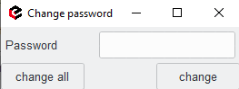
In case of a need for password change, a user can find the 'change password' button on the upper tools bar 'Extras'. After clicking Extras --> change password a new window will pop up. If the password is being changed for the first time, the user just needs to enter a new one and select if the new password will be applied for one or all of the connected devices. A new password should be entered in the Password field if configuration actions are needed, such as writing to the device, changing the address or changing the password again. Otherwise, an 'Incorrect password' error will pop up on the screen and parameters will not be applied.
Configuration
IOMODs can be configured directly by connecting to a device, or a configuration can be created from a template and then uploaded to the IOMOD. The IOMODs documentation provides more information about how to configure each specific IOMOD.
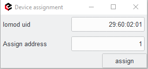
IOMOD Utility also allows users to configure more than one device at once. This could be done by creating a project. This process is briefly described in the User Interface chapter. The project button can be found in the upper tools bar. Project --> New creates a blank project and erases all changes made before. There is no need to click on Project --> New if the user opens the IOMOD Utility for the first time. Project --> open button opens an already saved project. To save a new project click Project --> Save. The project can also be saved as json file or in any other format needed by executing Project --> Save as and adding a required file extension. The project can be created by connecting a series of IOMODs in any way, as described later in the chapter. After clicking on the read device, each IOMOD will automatically assign a link address. The user can either click the assign button for each IOMOD or change the link address and then assign it. After this step, required changes can be made and a new project is saved in any form needed.
If the project needs to be created without connecting to IOMODs, this can be done by using templates. To add a new template device click on Device --> New --> then select the IOMOD type.
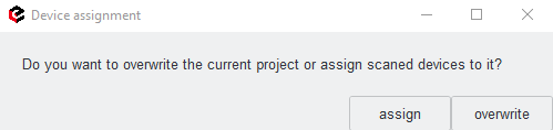
Each template's parameters can be changed and saved separately or together as a project. To apply the project parameters to IOMODs, first upload the project file to Utility, You will see the devices on the left side of the screen. Then connect the IOMODs physically and click scan devices, the Utility will then ask to assign a link address for each connected IOMOD. After all link addresses have been assigned, a new table will pop up asking if the project should be assigned or overwritten. Click assign to apply the saved project parameters to IOMODs.
The Utility will allow the user to choose which template should be assigned to which IOMOD if there is more than one of the same type.
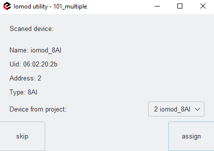
By clicking overwrite, the user will erase the changes made before and new parameters will be saved to the currently open project.
Note: when devices are scanned for the first time, link addresses are assigned to them. If a configuration from a project is applied, any new link addresses specified in the project will be ignored and not used.
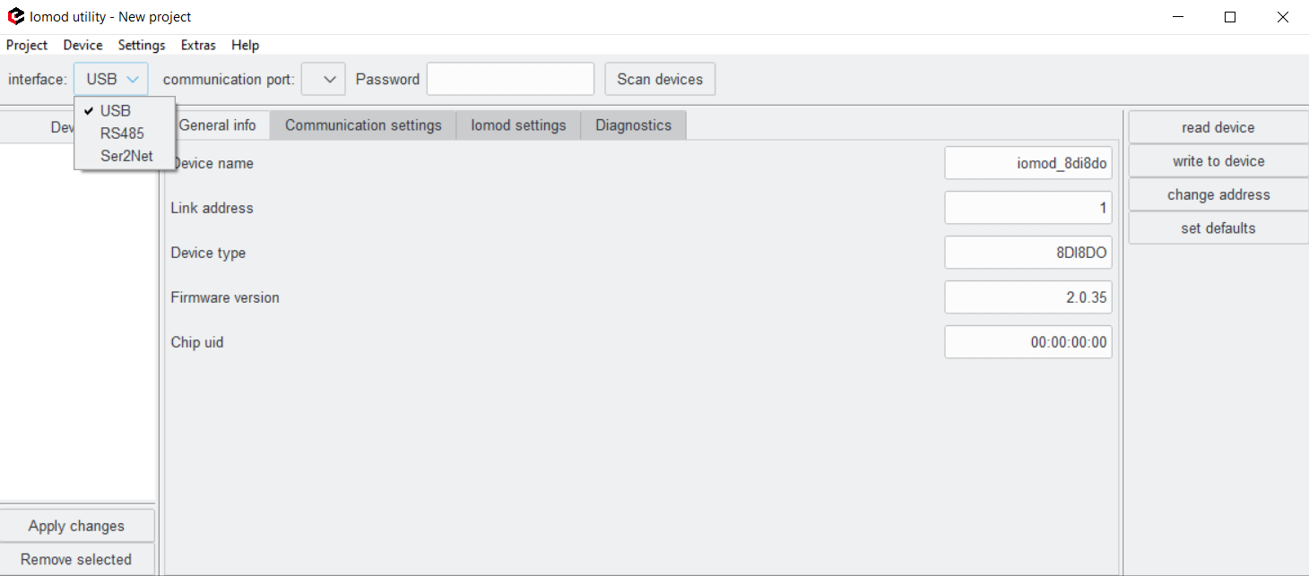
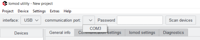
To configure an IOMOD directly, choose an interface first. Available interfaces are USB, RS485, and Ser2Net. To configure IOMOD via USB interface, IOMOD must be connected directly to the computer. The communication port will automatically be detected and can selected in the drop-down menu.
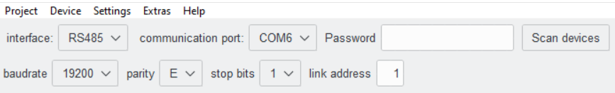
When configuring via RS485, an RS converter is needed. The converter must also be connected directly to the computer into one of the USB ports and to IOMOD itself via the RS485 port. In this case, IOMOD also needs to be powered up. The correct serial parameters for communication with IOMOD need to be selected. Default parameters are as shown in the picture below.
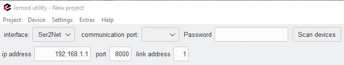
IP address, virtual port, and link address are needed to connect to IOMOD via the Ser2net port. The device to which IOMOD is connected needs to be configured accordingly. In this case, a physical communication port does not need to be specified in the Utility.
Other parameters are individual for each IOMOD and each protocol. More information about how to configure the specific IOMOD can be found in each IOMOD documentation. After the changes, it is important to click write to device button, otherwise the changes will not be applied.
Diagnostics
The Diagnostics tab allows the user to observe live data from IOMOD whether it is digital or analog values. On this tab, the user can also control devices if they have controllable outputs. This applies to IOMODs 8DI8DO and 8DI4RO. Diagnostics are possible by connecting IOMODs directly (USB or RS485) or remotely (Ser2Net). After scanning and connecting to the device, go to the Diagnostics tab and click on the Connect button to start observing live values. The data is updated every second. If communication is active it will be indicated with a blinking black dot near the green Online text in the upper right corner. If the communication breaks it will be indicated with the pop-up error message. While the device is offline it will be indicated with a red Offline text in the upper right corner of the Diagnostics tab. To stop the diagnostics click Disconnect.
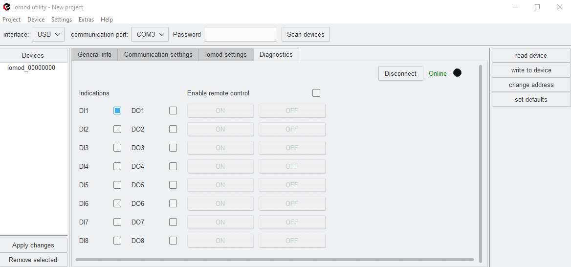
For IOMODs 8DO8DO and 8DI4RO, remote control can be enabled. By checking the Enable remote control box, the user can activate outputs directly from the IOMOD Utility. This can be done by clicking the ON and OFF buttons, where blue or grey squares indicate whether the output is activated or not.
Firmware upgrade
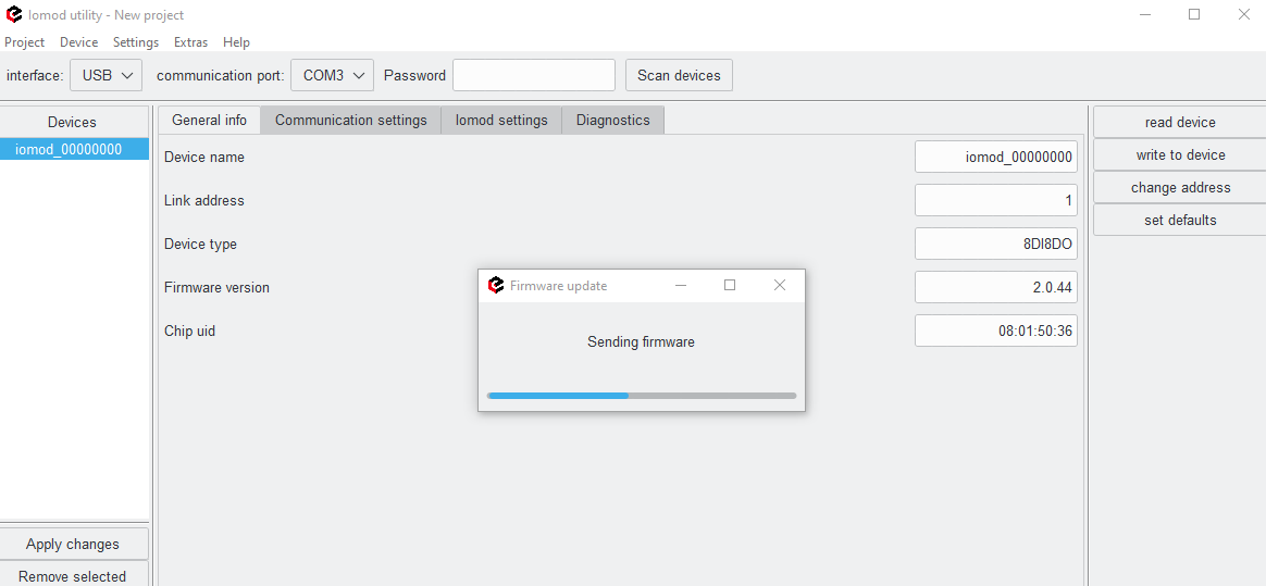
Users can upgrade the firmware using any chosen interface. Firmware upgrades can be done for more than one device at the same time. After connecting to a device, click on Scan device. After all the devices are visible on the left side of the window, click on Extras and choose either update firmware for all or update firmware for selected.
After choosing one of the options a mass storage window will open. Then by clicking on the firmware file and opening it, a firmware upgrade will start.
A message indicating that the firmware is uploaded will pop up if the upgrade was successful.
If there was an error while upgrading a firmware it could be done again, after scanning the devices again. If the scan is successful and devices are reachable, all the steps described above could be repeated.