Modbus
Modbus is a communications protocol originally published by Modicon (now Schneider Electric) in 1979 for use with its programmable logic controllers (PLCs). Simple and robust, it has since become a de facto standard communication protocol, and it is now a commonly available means of connecting industrial electronic devices.

Info about protocol
Address:
- IP address - every device in Ethernet have physical address (only for Ethernet)
- Station address - every slave (client) device have a logical address.
- Function - function type
- Address - information object address.
Telegram Structure
Modbus RTU
Request
|
Name |
Bytes |
Function |
|
Station |
0 |
Station address |
|
Function |
1 |
Function code |
|
Address Hi |
2 |
Starting address |
|
Address Lo |
3 |
|
|
Quantity Hi |
4 |
Quantity |
|
Quantity Lo |
5 |
|
|
CRC |
6 |
CRC check |
Response
|
Name |
Bytes |
Function |
|
Station |
0 |
Station address |
|
Function |
1 |
Function code |
|
Bytes |
2 |
Data bytes |
|
Data |
3... |
Data |
|
CRC |
Depending of data |
CRC check |
Modbus RTU/ASCII
|
Name |
Char |
Function |
|
Start |
0 |
: 0x3A |
|
Station |
1 |
Station address |
|
Function |
2 |
Function code |
|
Address Hi |
3 |
Starting address |
|
Address Lo |
4 |
|
|
Quantity Hi |
5 |
Quantity |
|
Quantity Lo |
6 |
|
|
LRC |
7 |
LRC check |
|
End |
8 |
ASCII values of 0x0D & 0x0A |
|
End |
9 |
Response
|
Name |
Char |
Function |
|
Start |
0 |
: 0x3A |
|
Station |
1 |
Station address |
|
Function |
2 |
Function code |
|
Bytes |
3 |
Data bytes |
|
Data |
4... |
Data |
|
LRC |
Depending of data |
LRC check |
|
End |
Depending of data |
ASCII values of 0x0D & 0x0A |
Modbus TCP
Request
|
Name |
Bytes |
Function |
|
Transaction Identifier |
0 |
For synchronization |
|
Transaction Identifier |
1 |
|
|
Protocol Identifier |
2 |
Zero for Modbus/TCP |
|
Protocol Identifier |
3 |
|
|
Length |
4 |
Number of remaining bytes in this frame |
|
Length |
5 |
|
|
Station |
6 |
Station address |
|
Function |
7 |
Function code |
|
Address Hi |
8 |
Starting address |
|
Address Lo |
9 |
|
|
Quantity Hi |
10 |
Quantity |
|
Quantity Lo |
11 |
Response
|
Name |
Bytes |
Function |
|
Transaction Identifier |
0 |
For synchronization |
|
Transaction Identifier |
1 |
|
|
Protocol Identifier |
2 |
Zero for Modbus/TCP |
|
Protocol Identifier |
3 |
|
|
Length |
4 |
Number of remaining bytes in this frame |
|
Length |
5 |
|
|
Station |
6 |
Station address |
|
Function |
7 |
Function code |
|
Bytes |
8 |
Data bytes |
|
Data |
9... |
Data |
Functions
Standard MODBUS functions
|
Dec |
Description |
Direction |
Support |
|
1 |
Read Coils |
Monitor |
Yes |
|
2 |
Read Discrete Inputs |
Monitor |
Yes |
|
3 |
Read Holding Registers |
Monitor |
Yes |
|
4 |
Read Input Registers |
Monitor |
Yes |
|
5 |
Write Single Coil |
Control |
Yes |
|
6 |
Write Single Register |
Control |
Yes |
|
7 |
Read Exception Status |
Monitor |
No |
|
8 |
Diagnostic |
Monitor |
No |
|
11 |
Get Com Event Counter |
Monitor |
No |
|
12 |
Get Com Event Log |
Monitor |
No |
|
15 |
Write Multiple Coils |
Control |
Yes |
|
16 |
Write Multiple Registers |
Control |
Yes |
|
17 |
Report Slave ID |
Monitor |
No |
|
20 |
Read File Record |
Monitor |
No |
|
21 |
Write File Record |
Control |
No |
|
22 |
Mask Write Register |
Control |
No |
|
23 |
Read/Write Multiple Registers |
Both |
No |
|
24 |
Read FIFO Queue |
Monitor |
No |
|
43 |
Read Device Identification |
Monitor |
No |
|
43 |
Encapsulated Interface Transport |
Monitor |
No |
Settings
MASTER |
|||
|---|---|---|---|
|
|
Modbus TCP |
Modbus Serial (ASCII included) |
|
|
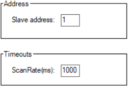
Slave address |
Address of the device which data is read from |
Address of the device which data is read from |
|
|
Scan Rate(ms) |
Interval between requests to data |
Interval between requests to data |
|
SLAVE |
|||
|
|
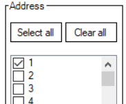
Address |
Select addresses of slaves to simulate |
Select addresses of slaves to simulate |
|
|
Value |
Default value which slaves will return from all registers. |
Default value which slaves will return from all registers. |

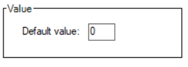
Default values are overridden by created Tags.
Functions
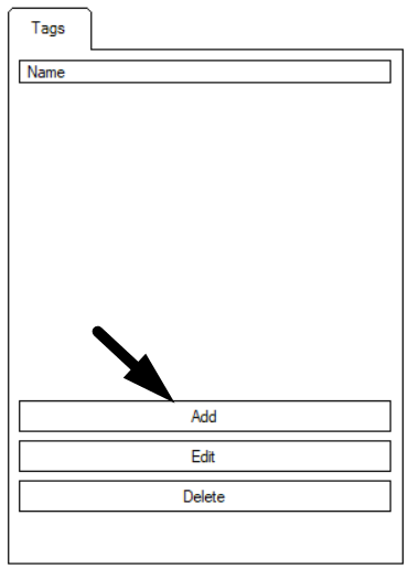
Tags
This function allows user to created named points. After points created, user can send it manually or set reply checkbox to automatic reply.
- To export Tags to csv file: Tags -> Export -> Save file dialog appear
- To import Tags from csv file: Tags -> Import -> Open file dialog appear


Creating Tag
In Modbus protocol tags are mostly used for Slaves to simulate specific data registers, although they can be used in Master to write data to slave registers or format received data from Slave devices.
There are two ways of creating tags:
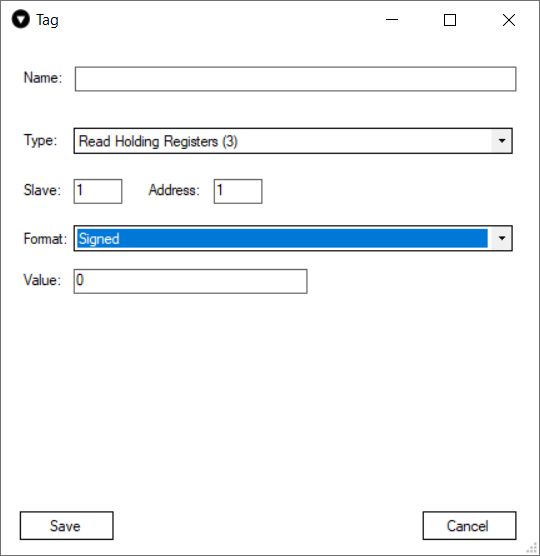
Slave
If the simulation mode is Slave a modbus tag creation window should look like this and have these parameters.
- Name - user-friendly tag name.
- Type - the function to be used. This means that if The Vinci software gets a request with the 03 function type and there is a tag created with that type and it matches the slave address and data address The Vinci software will respond to the request with the value that is set as the tag value.
- Slave - Slave address of tag.
- Address - Address of slave register.
- Format - Format to store or read data in.
- Value - Value of the register.
Master
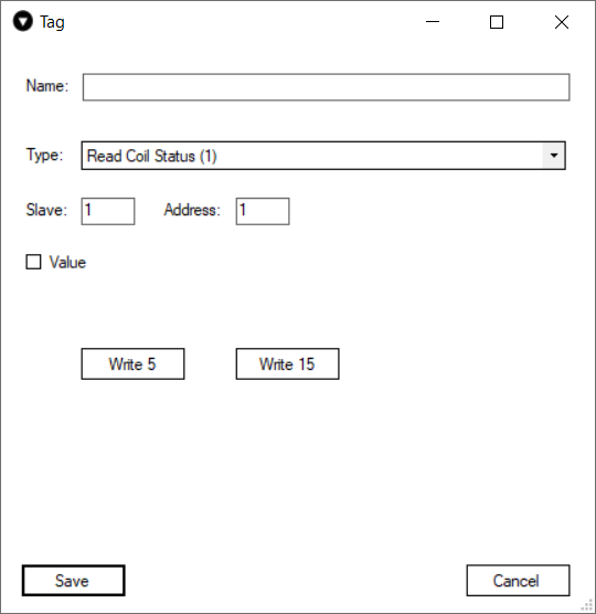
If the simulation mode is Master a modbus tag creation window should look like the one shown below and have these parameters.
In this case since this is the Master tag creation window it has two additional buttons that give the master the ability to write data to the Slave device. For the selected type he buttons are Write 5 and Write 15 correlating to the modbus types.
In Master applications tags are mostly used to format data read from Slaves since data reading from devices is done using Jobs.
For types 1 and 2 the buttons will be Write 5 and Write 15.
For types 3 and 4 the buttons will be Write 6 and Write 16
- Name - user-friendly tag name.
- Type - the type of data.
- Slave - Slave address of tag.
- Address - Adress of slave register.
- Format - Format to store or read data in.
- Value - Value of the register.
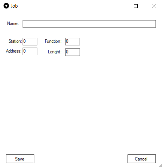
Jobs
Jobs are only available in Master simulations. What jobs are meant for is reading data from the Modbus slave device. They can send requests for big chunks of data in a single request. Then the data that slave responds with can be formatted using tags.
Job has these parameters:
- Name - user-friendly job name.
- Station - Modbus Slave address to read data from.
- Function - the function to be used to read data.
- Address - slave address to begin reading data from.
- Length - how many bytes will be read.
Command
Commands are only available in Master simulations. Commands are used to send data to Slave devices. They serve the same purpose as Write 5 and Write 6 buttons in tags.
Although, commands will send data to the Slave address configured in the Settings tab whereas tags will send the data to the Slave address configured in the tag configuration.
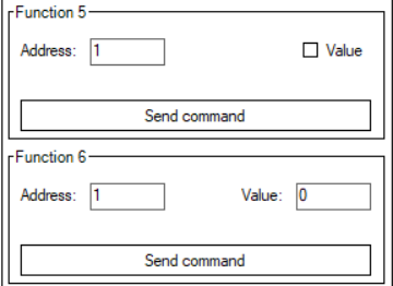
When using commands make sure to enter the desired Slave Address in the settings tab.
Setup
To setup an Modbus simulation it is fairly straightforward.
1. Select Modbus and the mode.
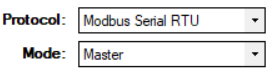
There are three different Modbus modes: Modbus TCP, Modbus Serial RTU, Modbus Serial ASCII.
2. Select Serial Port settings according to your device specification.

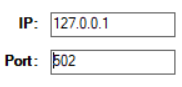
2.1 If Modbus TCP is used then the IP address and Port will have to be selected.
3. Select settings in the settings tab according to your device, preference and selected mode.
4. Press the green START button and the simulation should start. If everything was done correctly The Vinci software should establish communication with the Modbus device which you can monitor in the console tab.