| **Dec** | **Frame type** | **Service function** | **FCV** |
| 0 | SEND/CONFIRM expected | Reset of remote link | 0 |
| 1 | SEND/CONFIRM expected | Reset of user process | 0 |
| 2 | SEND/CONFIRM expected | Reserved | - |
| 3 | SEND/CONFIRM expected | User data | 1 |
| 4 | SEND/REPLY expected | User data | 0 |
| 5 | Reserved | - | |
| 6 | Reserved | - | |
| 7 | Reserved | - | |
| 8 | REQUEST for access demand | Expected response specifies access demand | 0 |
| 9 | REQUEST/RESPOND expected | Request status of link | 0 |
| 10 | REQUEST/RESPOND expected | Request user data class 1 | 1 |
| 11 | REQUEST/RESPOND expected | Request user data class 2 | 1 |
| 12 | Reserved | - | |
| 13 | Reserved | - | |
| 14 | Reserved | - | |
| 15 | Reserved | - |
| **Dec** | **Frame type** | **Service function** |
| 0 | CONFIRM | ACK: positive acknowledgment |
| 1 | CONFIRM | NACK: message not accepted, link busy |
| 2 | Reserved | |
| 3 | Reserved | |
| 4 | Reserved | |
| 5 | Reserved | |
| 6 | Reserved | |
| 7 | Reserved | |
| 8 | RESPOND | User data |
| 9 | RESPOND | NACK: requested data not available |
| 10 | Request user data class 1 | |
| 11 | RESPOND | Request user data class 2 |
| 12 | Reserved | |
| 13 | Reserved | |
| 14 | Reserved | |
| 15 | Reserved |
| **Dec** | **Description** | **Direction** | **Support** |
| 1 | Time-tagged message | Monitor | Yes |
| 2 | Time-tagged message with relative time | Monitor | Yes |
| 3 | Measurands I | Monitor | Yes |
| 4 | Time-tagged measurands with relative time | Monitor | Yes |
| 5 | Identification | Monitor | Yes |
| 6 | Clock synchronization | Both | Yes |
| 7 | General interrogation | Control | Yes |
| 8 | End of general interrogation | Monitor | Yes |
| 9 | Measurands II | Monitor | Yes |
| 10 | Generic data | Both | No |
| 11 | Generic identification | Monitor | No |
| 20 | General command | Control | Yes |
| 21 | Generic command | Control | No |
| 23 | List of recorded disturbances | Monitor | No |
| 24 | Order for disturbance data transmission | Control | No |
| 25 | Acknowledgment for disturbance data transmission | Control | No |
| 26 | Ready for transmission of disturbance data | Monitor | No |
| 27 | Ready for transmission of a channel | Monitor | No |
| 28 | Ready for transmission of tags | Monitor | No |
| 29 | Transmission of tags | Monitor | No |
| 30 | Transmission of disturbance values | Monitor | No |
| 31 | End of transmission | Monitor | No |
| **Dec** | **Description** |
| 1 | Spontaneous |
| 2 | Cyclic |
| 3 | Reset frame count bit ( FCB ) |
| 4 | Reset communication unit ( CU ) |
| 5 | Start/ restart |
| 6 | Power ON |
| 7 | Test mode |
| 8 | Time synchronization |
| 9 | General interrogation |
| 10 | End of general interrogation |
| 11 | Return information caused by a remote command |
| 12 | Return information caused by a local command |
| 20 | Command "ACK positive" |
| 21 | Command "ACK negative" |
| 31 | Transmission disturbance data |
| 40 | Generic write command with ACK positive |
| 41 | Generic write command with ACK negative |
| 42 | Generic read command data valid |
| 43 | Generic read command data invalid |
| 44 | Generic write conformation |
| **Timeouts (ms)** | ||||
| [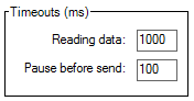](https://wiki.elseta.com/uploads/images/gallery/2022-01/image-1643031621517.png) | **Monitor** | **Master** | **Slave** | |
| **Reading data** | Waiting data in serial port buffer | Waiting data in serial port buffer | Waiting data in serial port buffer | |
| **Pause before send** | Not used | Pause before send data | Pause before send data | |
| **Address** | ||||
| [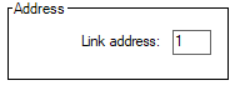](https://wiki.elseta.com/uploads/images/gallery/2022-01/image-1643031767819.png) | **Monitor** | **Master** | **Slave** | |
| **Link** | Not used | Remote device address | Own system address | |
| **ASDU** | Not used | Remote device address | Own system address | |
| **Commands ack.** | ||||
| [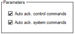](https://wiki.elseta.com/uploads/images/gallery/2022-01/image-1643031811132.png) | **Monitor** | **Master** | **Slave** | |
| **Auto ack. system commands** | Not used | Not used | Auto acknowledge system commands | |
| **Auto ack. control commands** | Not used | Not used | Auto acknowledge commands | |