The Vinci Software
This chapter covers ONLY The Vinci Software from v3.0.0. All older The Vinci Software versions are documented inside The Vinci Software about Chapter.
General
Introduction
Vinci protocol analyzer is an industrial communication tool for commissioning engineers and developers to simulate, analyze and test communication systems that use the IEC 60870-5 and Modbus protocols. With this software, you can monitor the communication channel - see what the master asks and what slaves answer. This makes it easier to diagnose and resolve communication issues between master and slave nodes in an industrial environment when troubleshooting or developing industrial applications and equipment.

What can it do?
You can use one of three operational modes: Master simulation, Slave simulation and Monitor mode. With each of these protocols, you can see how the communication is happening between each device and simulate them in your own specific way.
Master simulation gives the ability to simulate a master device for your slaves. You can use it to resolve remote problems with your SCADA systems or test a slave device before entering it into production.
Slave simulation gives the ability to simulate one or more slave devices, that way you can test out your SCADA system with specific data, or load.
Monitor mode is used when you need to see what is happening between the master and slave. It intercepts the data and gives you the ability to monitor the communication in an easy, readable format.
| IEC-60870-5-101 | Master |
| Slave | |
| Monitor | |
| IEC-60870-5-103 | Master |
| Slave | |
| Monitor | |
| IEC-60870-5-104 | Master |
| Slave | |
| Monitor | |
| Modbus (TCP, RTU, ASCII) | Master |
| Slave | |
| Monitor | |
| Serial port | Monitor |
Example use cases
For example, you can use Vinci to simulate a connection between a PLC and an HMI from your project. This is much easier than purchasing or installing both devices, and it’s a great way to troubleshoot your communication before you get stuck with real industrial equipment. You can also use Vinci for network monitoring of SCADA systems—it works with both MODBUS and IEC60870-5 protocols.
Quick-Start Guide
Vinci Hardware
Software Installation
The software can be downloaded from this link. After downloading the .exe installation file run it. The setup will open.
- To install The Vinci Software accept the license agreement and click next.
- Select Installation Destination Location and click Next.
- Select Start Menu Folder and click next.
- Choose whether to create a desktop shortcut
First Startup
Once the Vinci program is installed go to the install directory and open the Vinci application. A similar window as to the one below should open.
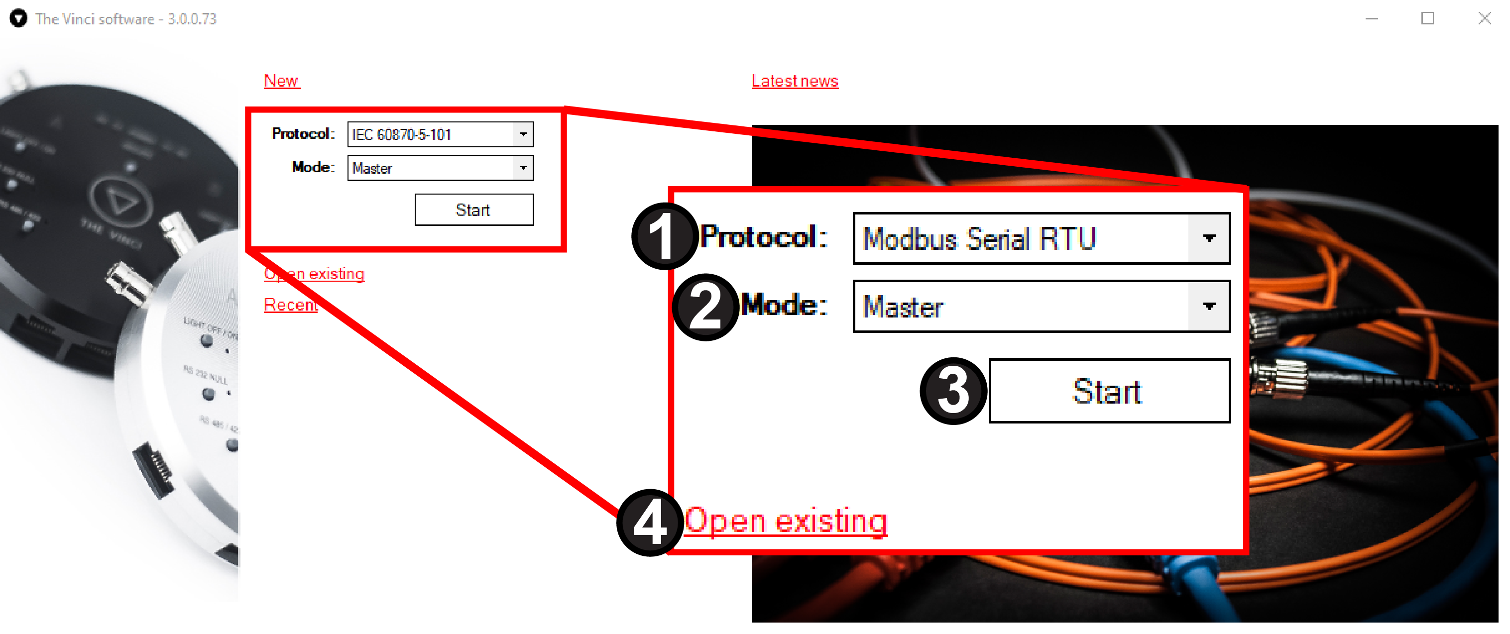
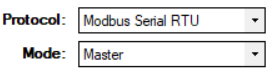
- Protocol selection :
- IEC 60870-5-101
- IEC 60870-5-103
- IEC 60870-5-104
- Modbus Serial RTU
- Modbus Serial ASCII
- Modbus TCP
- SerialPort
- Mode selection :
- Master
- Slave
- Monitor
- Start button to load configuration once selected.
- Open existing configuration file from the previous session.
Protocol specifics can be found here
After selecting the desired protocol pressing the start button will begin a new Vinci session and open a new file explorer prompt. There you can choose a save location and change the name of the file. After setting up the session this file will be saved automatically when you exit, so there is a possibility to save protocol configurations for future use. These configurations can be opened later by pressing the Open existing button on the app.
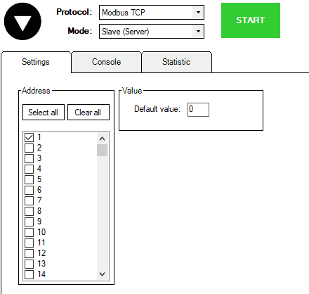
Depending on the protocol you chose a window similar to the one depicted below should open. (In this scenario it is a Modbus TCP Master session )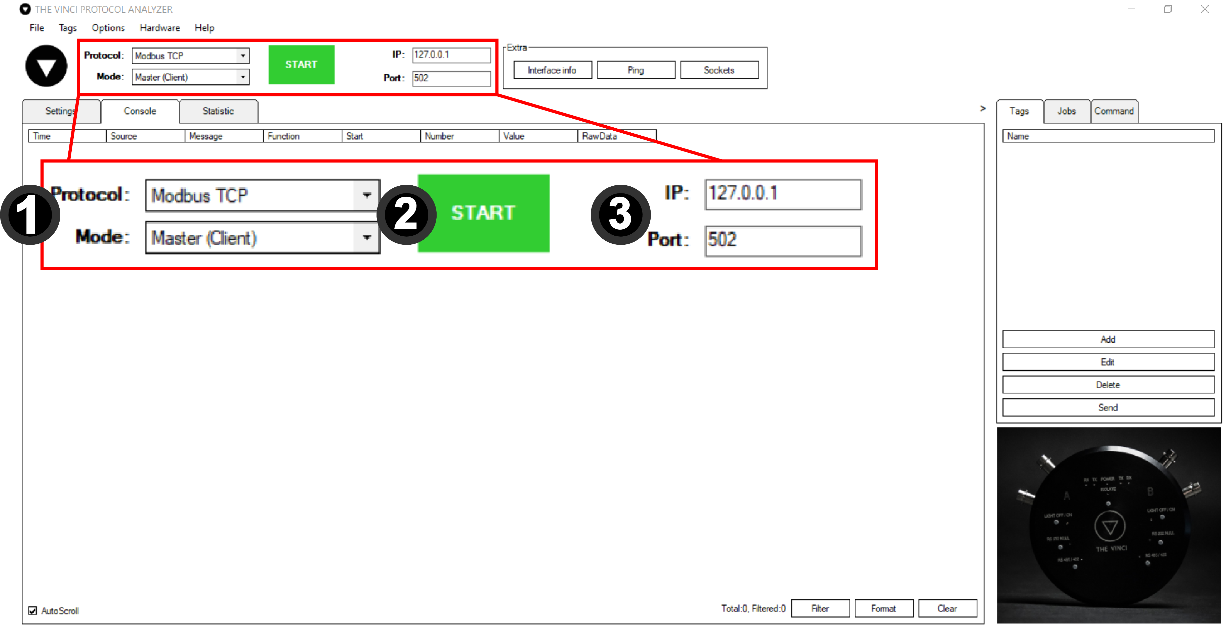
- Protocol selection and Mode selection like before.
- Start button to begin communication with the specified device.
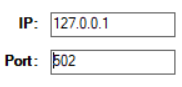
- Interface Selection. Depending on the protocol this can either be IP and Port or Serial connection parameters.
After configuring the interface pressing the start button should establish a connection to the specified interface. If the device is a Modbus TCP device.
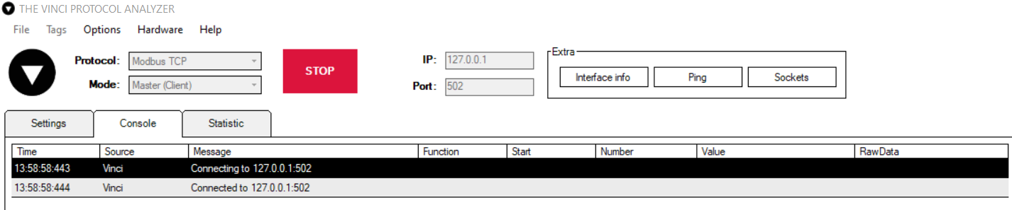
Now depending on the selected protocol Jobs, Tags and Commands can be configured.
To find more information on how to configure specific protocols click here
To find more information about the user interface click here
User Interface
Menu Bar
File
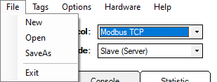
- New - Create new .vinci file.
- Open - Open existing .vinci file.
- SaveAs - Save current file with a different name.
- Exit - Close the program.
Tags
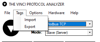
- Import - import previously saved .csv file.
- Export - export currently configured Tags to a .csv file.
To get more information about how tags work click here
Options

- Settings - opens settings window as depicted below.
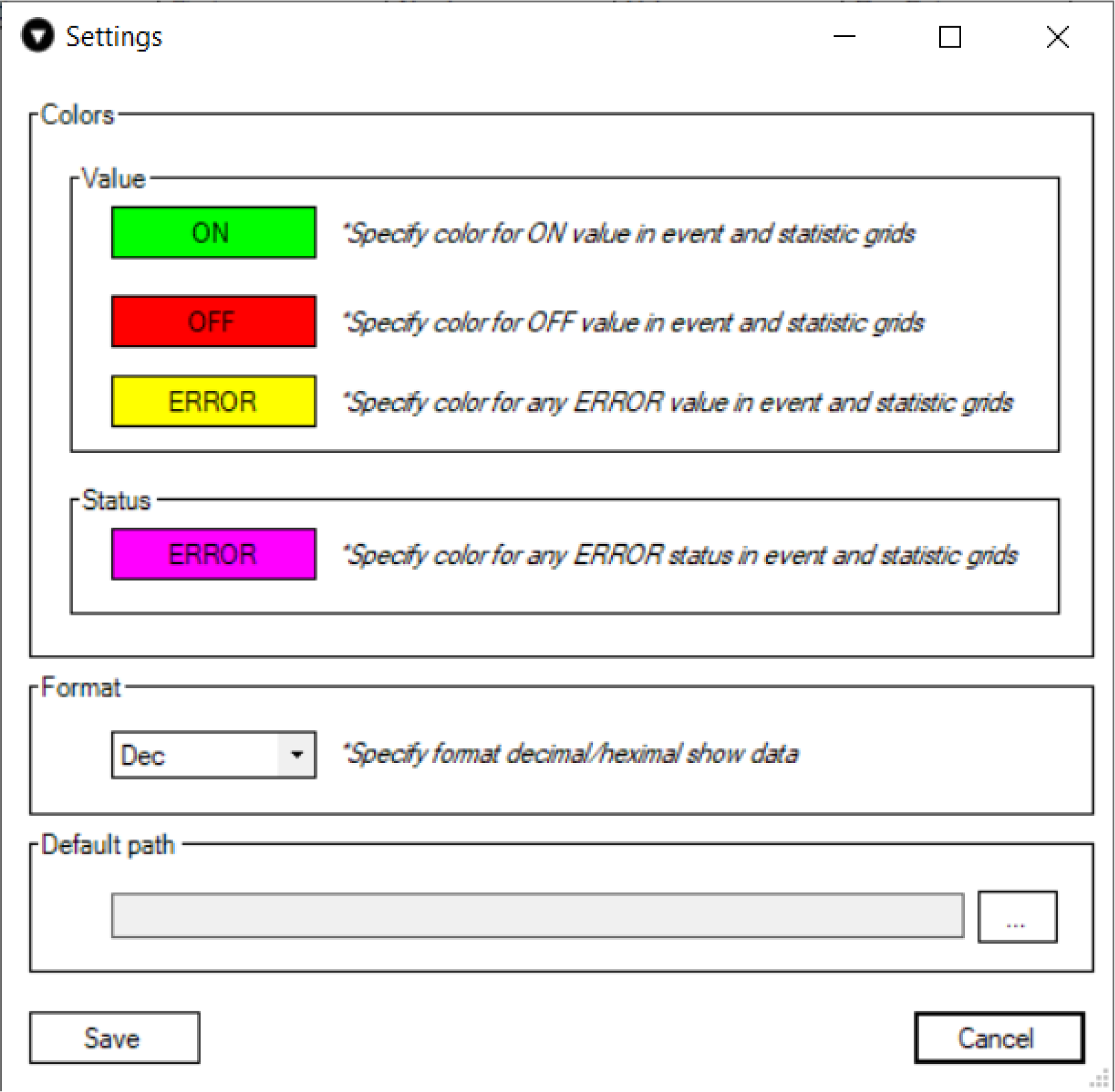
In this window you can choose:
- The colors that appear in the statistics menu.
- The format to show data. (Decimal or Hexadecimal)
- Default path to save session configuration.
Hardware
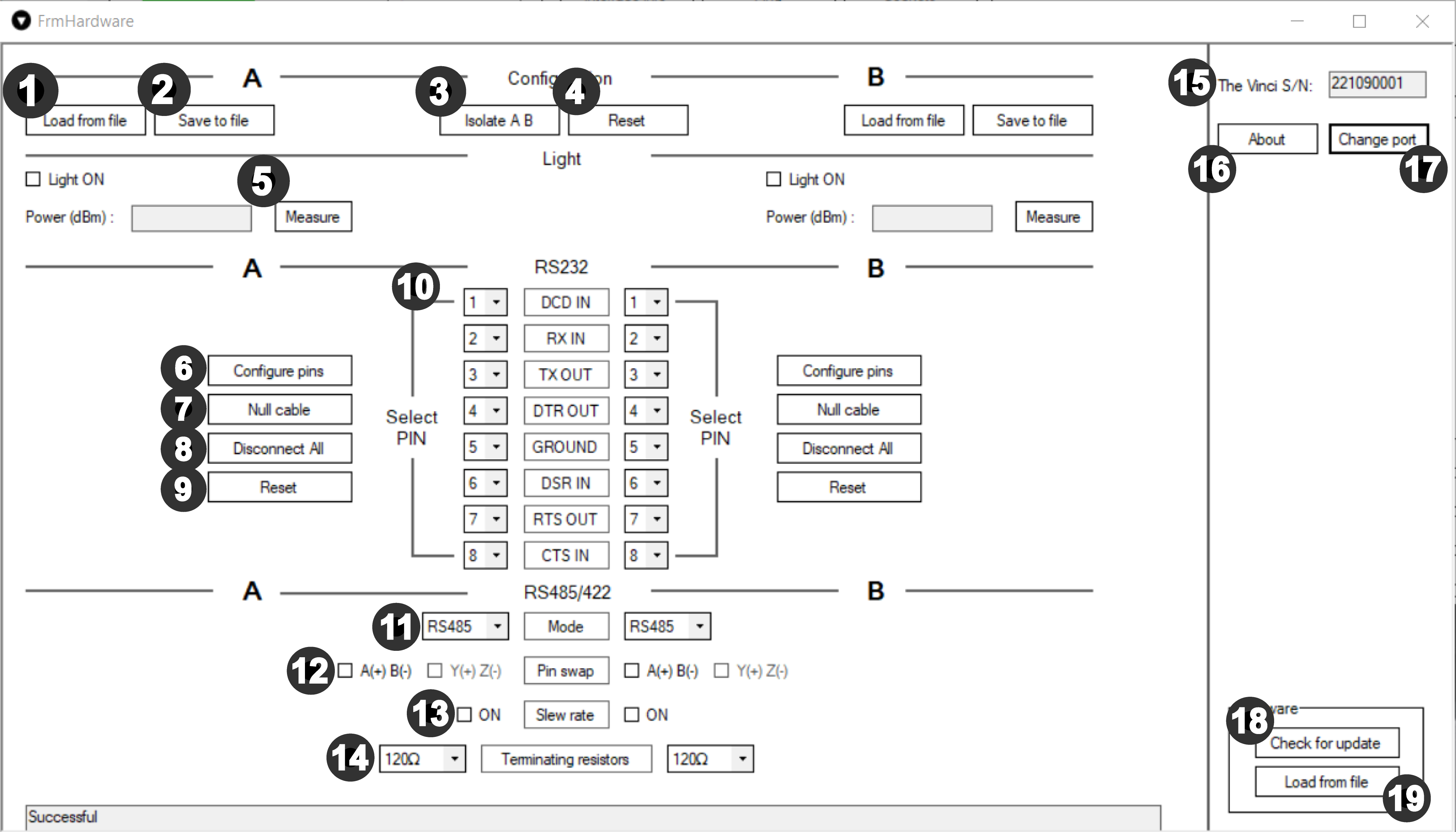
The Vinci Expert device must be connected for this tab to work.
All of the settings are for A and B sides respectively except 3,4,15,16,17,18,19.
In this tab, The Vinci Expert device configuration may be changed.
- Load from file - Configuration can be loaded for A and B side separately.
- Save to file - Save hardware configuration for further use.
- Isolate A B - by clicking this button isolation of The Vinci can be changed. It has the same functionality as the physical Isolate button.
- Non isolated
- The Vinci works like analyser/proble. Everything that comes to A side, comes out of B side and in reverse - what comes in B side goes to A side.
- Isolated
-
By pressing "Isolate A B" button, it isolates serial interface A side from B side. That means Vinci works like protocol master / slave. Everything that comes to A side, comes out of A side and in reverse – what comes in B side, goes out of B side.
-
- Non isolated
- Reset - The Vinci Expert resets to default settings.
- All previous settings, including software-defined, will be set to defaults.
- When the reset button is activated all lights flash clockwise once and the power indicator stays green.
- When the Vinci is programmed by software, the power indicator stays red.
-
Convert Fiber Optical channel from Light Off mode to Light On mode for A and B side separately.
Measure - press this button to measure Light signal power in (dBm). 820nm is nominal wavelength.
- Configure pins - The Vinci Expert connects pins like in the specified configuration. (Configuration at 10)
- Null cable - by pressing this button you can switch modem cable mode to null.
- Disconnect All - disconnects all pin from connector.
- Reset - the pins will be reset to default RS232 pin sequence.
- Here RJ-45 pins can be assigned with RS232 signals for both A and B sides separately
- Mode - Selection between RS485 and RS422 serial interface.
- Pin swap - in RS485 A(+)B(-) differential pair can be swapped. Using RS422 mode, A(+)B(-) and Y(+)Z(-) differential pairs can be swapped respectively.
- Slew rate - slower slew rate can be enabled.
- Terminating resistors - selectable 100 Ohm, 120 Ohm or no termination resistor RT on RS485 and RS422.
- The serial number of the connected the Vinci device.
- About - more information about The Vinci Expert device, incl. serial number and Firmware version.
- Change Port - change the control port of the The Vinci Expert device. Used when several The Vinci Expert devices are used.
- Check for update - automatically updates The Vinci Expert firmware version.
- Load from file - firmware can be updated from file.
Help
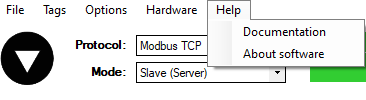
- Documentation - links to the wiki.
- About software - information about software and terms and conditions.
Settings
Protocol specific settings for the simulated device.
Protocol specifics can be found here
Console

Console log of all messages recieved and sent.
Statistic
In this tab you can see all the signal values that the Vinci Software has read from the configured device. In this example you can see values read from 8DI8DO IOMod after general interrogation

Filter and Formatting
Placement
Filter and Format buttons can be found at the bottom right side of the Console window, as demonstrated in the picture below

Filter
Filtering refers to comparing a list of records against specific criteria and then hiding the records that don’t match the criteria. It can be used simply to help find a record, or to create a subset of data that you can then format and copy without affecting the other records.
In the console window, you can filter the log messages by certain parameters of a protocol. To set up a filter you press the Filter button and select wanted options that are specific to the chosen protocol. The options are explained in their specific protocol page.
Only 2 main boxes are persistent thriought all protocols:
- Enabled - toggle if you want to enable the filter.
- Show system messages - toggle to filter out system messages. E.g. "Can't open serial port: COMx"
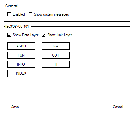
If the filter is enabled, the button will appear red.

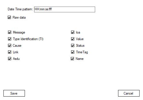
Formatting
Formatting refers to changing how data is displayed to the user. You can edit how much data is shown, what type of fields you want to see, how the date should be displayed. All the format options besides date time are specific to the chosen protocol.
Tags
Slave:
Master:
All tags are protocol-specific.
Protocol Specific
Modbus
Modbus is a communications protocol originally published by Modicon (now Schneider Electric) in 1979 for use with its programmable logic controllers (PLCs). Simple and robust, it has since become a de facto standard communication protocol, and it is now a commonly available means of connecting industrial electronic devices.

Info about protocol
Address:
- IP address - every device in Ethernet have physical address (only for Ethernet)
- Station address - every slave (client) device have a logical address.
- Function - function type
- Address - information object address.
Telegram Structure
Modbus RTU
Request
|
Name |
Bytes |
Function |
|
Station |
0 |
Station address |
|
Function |
1 |
Function code |
|
Address Hi |
2 |
Starting address |
|
Address Lo |
3 |
|
|
Quantity Hi |
4 |
Quantity |
|
Quantity Lo |
5 |
|
|
CRC |
6 |
CRC check |
Response
|
Name |
Bytes |
Function |
|
Station |
0 |
Station address |
|
Function |
1 |
Function code |
|
Bytes |
2 |
Data bytes |
|
Data |
3... |
Data |
|
CRC |
Depending of data |
CRC check |
Modbus RTU/ASCII
|
Name |
Char |
Function |
|
Start |
0 |
: 0x3A |
|
Station |
1 |
Station address |
|
Function |
2 |
Function code |
|
Address Hi |
3 |
Starting address |
|
Address Lo |
4 |
|
|
Quantity Hi |
5 |
Quantity |
|
Quantity Lo |
6 |
|
|
LRC |
7 |
LRC check |
|
End |
8 |
ASCII values of 0x0D & 0x0A |
|
End |
9 |
Response
|
Name |
Char |
Function |
|
Start |
0 |
: 0x3A |
|
Station |
1 |
Station address |
|
Function |
2 |
Function code |
|
Bytes |
3 |
Data bytes |
|
Data |
4... |
Data |
|
LRC |
Depending of data |
LRC check |
|
End |
Depending of data |
ASCII values of 0x0D & 0x0A |
Modbus TCP
Request
|
Name |
Bytes |
Function |
|
Transaction Identifier |
0 |
For synchronization |
|
Transaction Identifier |
1 |
|
|
Protocol Identifier |
2 |
Zero for Modbus/TCP |
|
Protocol Identifier |
3 |
|
|
Length |
4 |
Number of remaining bytes in this frame |
|
Length |
5 |
|
|
Station |
6 |
Station address |
|
Function |
7 |
Function code |
|
Address Hi |
8 |
Starting address |
|
Address Lo |
9 |
|
|
Quantity Hi |
10 |
Quantity |
|
Quantity Lo |
11 |
Response
|
Name |
Bytes |
Function |
|
Transaction Identifier |
0 |
For synchronization |
|
Transaction Identifier |
1 |
|
|
Protocol Identifier |
2 |
Zero for Modbus/TCP |
|
Protocol Identifier |
3 |
|
|
Length |
4 |
Number of remaining bytes in this frame |
|
Length |
5 |
|
|
Station |
6 |
Station address |
|
Function |
7 |
Function code |
|
Bytes |
8 |
Data bytes |
|
Data |
9... |
Data |
Functions
Standard MODBUS functions
|
Dec |
Description |
Direction |
Support |
|
1 |
Read Coils |
Monitor |
Yes |
|
2 |
Read Discrete Inputs |
Monitor |
Yes |
|
3 |
Read Holding Registers |
Monitor |
Yes |
|
4 |
Read Input Registers |
Monitor |
Yes |
|
5 |
Write Single Coil |
Control |
Yes |
|
6 |
Write Single Register |
Control |
Yes |
|
7 |
Read Exception Status |
Monitor |
No |
|
8 |
Diagnostic |
Monitor |
No |
|
11 |
Get Com Event Counter |
Monitor |
No |
|
12 |
Get Com Event Log |
Monitor |
No |
|
15 |
Write Multiple Coils |
Control |
Yes |
|
16 |
Write Multiple Registers |
Control |
Yes |
|
17 |
Report Slave ID |
Monitor |
No |
|
20 |
Read File Record |
Monitor |
No |
|
21 |
Write File Record |
Control |
No |
|
22 |
Mask Write Register |
Control |
No |
|
23 |
Read/Write Multiple Registers |
Both |
No |
|
24 |
Read FIFO Queue |
Monitor |
No |
|
43 |
Read Device Identification |
Monitor |
No |
|
43 |
Encapsulated Interface Transport |
Monitor |
No |
Settings
MASTER |
|||
|---|---|---|---|
|
|
Modbus TCP |
Modbus Serial (ASCII included) |
|
|
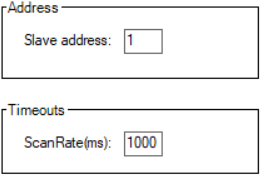
Slave address |
Address of the device which data is read from |
Address of the device which data is read from |
|
|
Scan Rate(ms) |
Interval between requests to data |
Interval between requests to data |
|
SLAVE |
|||
|
|
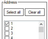
Address |
Select addresses of slaves to simulate |
Select addresses of slaves to simulate |
|
|
Value |
Default value which slaves will return from all registers. |
Default value which slaves will return from all registers. |

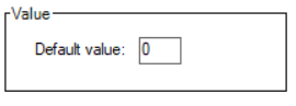
Default values are overridden by created Tags.
Functions
Tags
This function allows user to created named points. After points created, user can send it manually or set reply checkbox to automatic reply.
- To export Tags to csv file: Tags -> Export -> Save file dialog appear
- To import Tags from csv file: Tags -> Import -> Open file dialog appear


Creating Tag
In Modbus protocol tags are mostly used for Slaves to simulate specific data registers, although they can be used in Master to write data to slave registers or format received data from Slave devices.
There are two ways of creating tags:
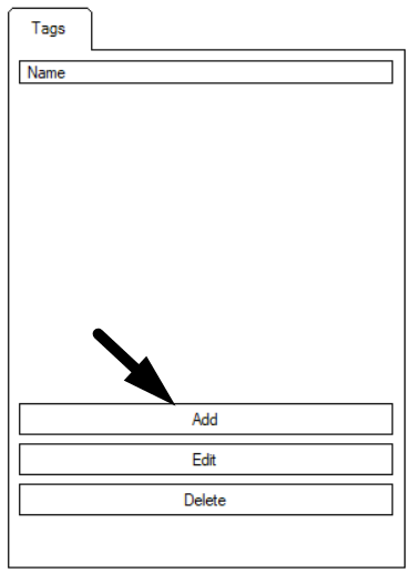
Slave
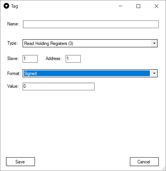
If the simulation mode is Slave a modbus tag creation window should look like this and have these parameters.
- Name - user-friendly tag name.
- Type - the function to be used. This means that if The Vinci software gets a request with the 03 function type and there is a tag created with that type and it matches the slave address and data address The Vinci software will respond to the request with the value that is set as the tag value.
- Slave - Slave address of tag.
- Address - Address of slave register.
- Format - Format to store or read data in.
- Value - Value of the register.
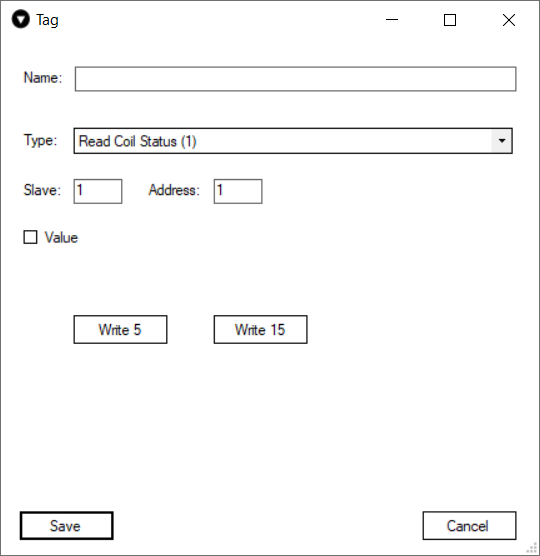
Master
If the simulation mode is Master a modbus tag creation window should look like the one shown below and have these parameters.
In this case since this is the Master tag creation window it has two additional buttons that give the master the ability to write data to the Slave device. For the selected type he buttons are Write 5 and Write 15 correlating to the modbus types.
In Master applications tags are mostly used to format data read from Slaves since data reading from devices is done using Jobs.
For types 1 and 2 the buttons will be Write 5 and Write 15.
For types 3 and 4 the buttons will be Write 6 and Write 16
- Name - user-friendly tag name.
- Type - the type of data.
- Slave - Slave address of tag.
- Address - Adress of slave register.
- Format - Format to store or read data in.
- Value - Value of the register.
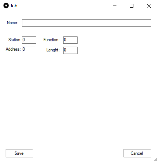
Jobs
Jobs are only available in Master simulations. What jobs are meant for is reading data from the Modbus slave device. They can send requests for big chunks of data in a single request. Then the data that slave responds with can be formatted using tags.
Job has these parameters:
- Name - user-friendly job name.
- Station - Modbus Slave address to read data from.
- Function - the function to be used to read data.
- Address - slave address to begin reading data from.
- Length - how many bytes will be read.
Command
Commands are only available in Master simulations. Commands are used to send data to Slave devices. They serve the same purpose as Write 5 and Write 6 buttons in tags.
Although, commands will send data to the Slave address configured in the Settings tab whereas tags will send the data to the Slave address configured in the tag configuration.
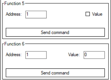
When using commands make sure to enter the desired Slave Address in the settings tab.
Setup
To setup an Modbus simulation it is fairly straightforward.
1. Select Modbus and the mode.
There are three different Modbus modes: Modbus TCP, Modbus Serial RTU, Modbus Serial ASCII.
2. Select Serial Port settings according to your device specification.

2.1 If Modbus TCP is used then the IP address and Port will have to be selected.
3. Select settings in the settings tab according to your device, preference and selected mode.
4. Press the green START button and the simulation should start. If everything was done correctly The Vinci software should establish communication with the Modbus device which you can monitor in the console tab.

IEC 60870-5-101
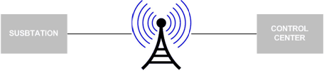
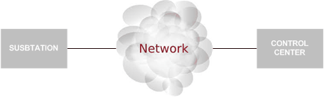
IEC 60870-5-101 is a protocol for power system monitoring and controlling. Mostly used for communication between substations and control centers over radio.
Info about protocol
Telegram Structure
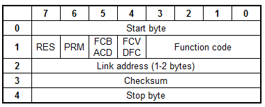
Teleram format with fixed length
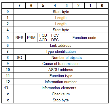
Telegram format with variable length
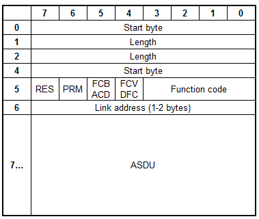
- RES - Reserved
- PRM - 1 if master, 0 if slave
PRM = 1
- FCB - alternating bit for successive services per station
- FCV - (if FCV=1 FCB enabled)
PRM = 0
- ACD - access demand (if ACD=1 there are class 1 data)
- DFC - data flow control (if DFC=1 further messages may cause data overflow)
ASDU - Application Service Data Unit
Function Code
PRM=1
|
Dec |
Frame type |
Service function |
FCV |
|
0 |
SEND/CONFIRM expected |
Reset of remote link |
0 |
|
1 |
SEND/CONFIRM expected |
Reset of user process |
0 |
|
2 |
SEND/CONFIRM expected |
Reserved |
- |
|
3 |
SEND/CONFIRM expected |
User data |
1 |
|
4 |
SEND/REPLY expected |
User data |
0 |
|
5 |
|
Reserved |
- |
|
6 |
|
Reserved |
- |
|
7 |
|
Reserved |
- |
|
8 |
REQUEST for access demand |
Expected response specifies access demand |
0 |
|
9 |
REQUEST/RESPOND expected |
Request status of link |
0 |
|
10 |
REQUEST/RESPOND expected |
Request user data class 1 |
1 |
|
11 |
REQUEST/RESPOND expected |
Request user data class 2 |
1 |
|
12 |
|
Reserved |
- |
|
13 |
|
Reserved |
- |
|
14 |
|
Reserved |
- |
|
15 |
|
Reserved |
- |
PRM=0
|
Dec |
Frame type |
Service function |
|
0 |
CONFIRM |
ACK: positive acknowledgment |
|
1 |
CONFIRM |
NACK: message not accepted, link busy |
|
2 |
|
Reserved |
|
3 |
|
Reserved |
|
4 |
|
Reserved |
|
5 |
|
Reserved |
|
6 |
|
Reserved |
|
7 |
|
Reserved |
|
8 |
RESPOND |
User data |
|
9 |
RESPOND |
Requested data not available |
|
10 |
|
Reserved |
|
11 |
RESPOND |
Status of link |
|
12 |
|
Reserved |
|
13 |
|
Reserved |
|
14 |
|
Reserved |
|
15 |
|
Reserved |
Type identification
Standard IEC 60870-5-101 data types[1-255]
•[1-127] - standard definition
•[128-135] - reserved for routing of messages
•[136-255] - for special use
|
Dec |
Type |
Description |
Direction |
Support |
|
Process information |
||||
|
1 |
M_SP_NA_1 |
Single-point information |
Monitor |
Yes |
|
2 |
M_SP_TA_1 |
Single-point information with time tag |
Monitor |
Yes |
|
3 |
M_DP_NA_1 |
Double-point information |
Monitor |
Yes |
|
4 |
M_DP_TA_1 |
Double-point information with time tag |
Monitor |
Yes |
|
5 |
M_ST_NA_1 |
Step position information |
Monitor |
Yes |
|
6 |
M_ST_TA_1 |
Step position information with time tag |
Monitor |
Yes |
|
7 |
M_BO_NA_1 |
Bit string of 32 bit |
Monitor |
Yes |
|
8 |
M_BO_TA_1 |
Bit string of 32 bit with time tag |
Monitor |
Yes |
|
9 |
M_ME_NA_1 |
Measured value, normalized value |
Monitor |
Yes |
|
10 |
M_ME_TA_1 |
Measured value, normalized value with time tag |
Monitor |
Yes |
|
11 |
M_ME_NB_1 |
Measured value, scaled value |
Monitor |
Yes |
|
12 |
M_ME_TB_1 |
Measured value, scaled value wit time tag |
Monitor |
Yes |
|
13 |
M_ME_NC_1 |
Measured value, short floating point number |
Monitor |
Yes |
|
14 |
M_ME_TC_1 |
Measured value, short floating point number with time tag |
Monitor |
Yes |
|
15 |
M_IT_NA_1 |
Integrated totals |
Monitor |
Yes |
|
16 |
M_IT_TA_1 |
Integrated totals with time tag |
Monitor |
Yes |
|
17 |
M_EP_TA_1 |
Event of protection equipment with time tag |
Monitor |
Yes |
|
18 |
M_EP_TB_1 |
Packed start events of protection equipment with time tag |
Monitor |
Yes |
|
19 |
M_EP_TC_1 |
Packed output circuit information of protection equipment with time tag |
Monitor |
Yes |
|
20 |
M_PS_NA_1 |
Packed single point information with status change detection |
Monitor |
Yes |
|
21 |
M_ME_ND_1 |
Measured value, normalized value without quality descriptor |
Monitor |
Yes |
|
30 |
M_SP_TB_1 |
Single-point information with time tag CP56Time2a |
Monitor |
Yes |
|
31 |
M_DP_TB_1 |
Double-point information with time tag CP56Time2a |
Monitor |
Yes |
|
32 |
M_ST_TB_1 |
Step position information with time tag CP56Time2a |
Monitor |
Yes |
|
33 |
M_BO_TB_1 |
Bit string of 32 bit with time tag CP56Time2a |
Monitor |
Yes |
|
34 |
M_ME_TD_1 |
Measured value, normalized value with time tag CP56Time2a |
Monitor |
Yes |
|
35 |
M_ME_TE_1 |
Measured value, scaled value with time tag CP56Time2a |
Monitor |
Yes |
|
36 |
M_ME_TF_1 |
Measured value, short floating point number with time tag CP56Time2a |
Monitor |
Yes |
|
37 |
M_IT_TB_1 |
Integrated totals with time tag CP56Time2a |
Monitor |
Yes |
|
38 |
M_EP_TD_1 |
Event of protection equipment with time tag CP56Time2a |
Monitor |
Yes |
|
39 |
M_EP_TE_1 |
Packed start events of protection equipment with time tag CP56Time2a |
Monitor |
Yes |
|
40 |
M_EP_TF_1 |
Packed output circuit information of protection equipment with time tag CP56Time2a |
Monitor |
Yes |
|
45 |
C_SC_NA_1 |
Single command |
Control |
Yes |
|
46 |
C_DC_NA_1 |
Double command |
Control |
Yes |
|
47 |
C_RC_NA_1 |
Regulating step command |
Control |
Yes |
|
48 |
C_SE_NA_1 |
Set-point Command, normalized value |
Control |
Yes |
|
49 |
C_SE_NB_1 |
Set-point Command, scaled value |
Control |
Yes |
|
50 |
C_SE_NC_1 |
Set-point Command, short floating point number |
Control |
Yes |
|
51 |
C_BO_NA_1 |
Bit string 32 bit command |
Control |
Yes |
|
58 |
C_SC_TA_1 |
Single command with time tag CP56Time2a |
Control |
Yes |
|
59 |
C_DC_TA_1 |
Double command with time tag CP56Time2a |
Control |
Yes |
|
60 |
C_RC_TA_1 |
Regulating step command with time tag CP56Time2a |
Control |
Yes |
|
61 |
C_SE_TA_1 |
Measured value, normalized value command with time tag CP56Time2a |
Control |
Yes |
|
62 |
C_SE_TB_1 |
Measured value, scaled value command with time tag CP56Time2a |
Control |
Yes |
|
63 |
C_SE_TC_1 |
Measured value, short floating point number command with time tag CP56Time2a |
Control |
Yes |
|
64 |
C_BO_TA_1 |
Bit string of 32 bit command with time tag CP56Time2a |
Control |
Yes |
|
System information |
||||
|
70 |
M_EI_NA_1 |
End of Initialization |
Monitor |
Yes |
|
100 |
C_IC_NA_1 |
Interrogation command |
Control |
Yes |
|
101 |
C_CI_NA_1 |
Counter interrogation command |
Control |
Yes |
|
102 |
C_RD_NA_1 |
Read command |
Control |
Yes |
|
103 |
C_CS_NA_1 |
Clock synchronization command |
Control |
Yes |
|
104 |
C_TS_NA_1 |
Test command |
Control |
Yes |
|
105 |
C_RP_NA_1 |
Reset process command |
Control |
Yes |
|
106 |
C_CD_NA_1 |
Delay acquisition command |
Control |
No |
|
107 |
C_TS_TA_1 |
Test command with time tag CP56Time2a |
Control |
No |
|
Parameter |
||||
|
110 |
P_ME_NA_1 |
Parameter of measured values, normalized value |
Control |
No |
|
111 |
P_ME_NB_1 |
Parameter of measured values, scaled value |
Control |
No |
|
112 |
P_ME_NC_1 |
Parameter of measured values, short floating point number |
Control |
No |
|
113 |
P_AC_NA_1 |
Parameter activation |
Control |
No |
|
File transfer |
||||
|
120 |
F_FR_NA_1 |
File ready |
File transfer |
No |
|
121 |
F_SR_NA_1 |
Section ready |
File transfer |
No |
|
122 |
F_SC_NA_1 |
Call directory, select file, call file, call section |
File transfer |
No |
|
123 |
F_LS_NA_1 |
Last section, last segment |
File transfer |
No |
|
124 |
F_FA_NA_1 |
ACK file, ACK section |
File transfer |
No |
|
125 |
F_SG_NA_1 |
Segment |
File transfer |
No |
|
126 |
F_DR_TA_1 |
Directory |
File transfer |
No |
Cause of transmission
Standard IEC 60870-5-101 cause of transmission [0-63]
|
Dec |
Description |
|
1 |
Periodic, cyclic |
|
2 |
Background interrogation |
|
3 |
Spontaneous |
|
4 |
Initialized |
|
5 |
Interrogation or interrogated |
|
6 |
Activation |
|
7 |
Confirmation activation |
|
8 |
Deactivation |
|
9 |
Confirmation deactivation |
|
10 |
Termination activation |
|
11 |
Return information caused by a remote command |
|
12 |
Return information caused by a local command |
|
13 |
File transfer |
|
20 |
Interrogated by general interrogation |
|
21 |
Interrogated by interrogation group 1 |
|
22 |
Interrogated by interrogation group 2 |
|
23 |
Interrogated by interrogation group 3 |
|
24 |
Interrogated by interrogation group 4 |
|
25 |
Interrogated by interrogation group 5 |
|
26 |
Interrogated by interrogation group 6 |
|
27 |
Interrogated by interrogation group 7 |
|
28 |
Interrogated by interrogation group 8 |
|
29 |
Interrogated by interrogation group 9 |
|
30 |
Interrogated by interrogation group 10 |
|
31 |
Interrogated by interrogation group 11 |
|
32 |
Interrogated by interrogation group 12 |
|
33 |
Interrogated by interrogation group 13 |
|
34 |
Interrogated by interrogation group 14 |
|
35 |
Interrogated by interrogation group 15 |
|
36 |
Interrogated by interrogation group 16 |
|
37 |
Interrogated by counter general interrogation |
|
38 |
Interrogated by interrogation counter group 1 |
|
39 |
Interrogated by interrogation counter group 2 |
|
40 |
Interrogated by interrogation counter group 3 |
|
41 |
Interrogated by interrogation counter group 4 |
|
44 |
Type Identification unknown |
|
45 |
Cause unknown |
|
46 |
ASDU address unknown |
|
47 |
Information object address unknown |
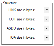
Settings
|
Structure |
||||
|
|
|
Monitor |
Master |
Slave |
|
LINK size in bytes |
LINK size in bytes |
LINK size in bytes |
LINK size in bytes |
|
|
COT size in bytes |
COT size in bytes |
COT size in bytes |
COT size in bytes |
|
|
ASDU size in bytes |
ASDU size in bytes |
ASDU size in bytes |
ASDU size in bytes |
|
|
IOA size in bytes |
IOA size in bytes |
IOA size in bytes |
IOA size in bytes |
|
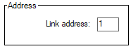
|
Address |
||||
|
|
|
Monitor |
Master |
Slave |
|
Link address |
Not used |
Remote device address |
Own system address |
|
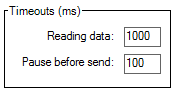
|
Timeouts (ms) |
||||
|
|
|
Monitor |
Master |
Slave |
|
Reading data |
Waiting data in serial port buffer |
Waiting data in serial port buffer |
Waiting data in serial port buffer |
|
|
Pause before send |
Not used |
Pause before send data |
Pause before send data |
|
|
Parameters |
||||
|
|
|
Monitor |
Master |
Slave |
|
Send End of ini. |
Not used |
Not used |
Send end of initialization TI 70 (M_EI_NA_1) |
|
| Auto ack. control commands |
Not used |
Not used |
Auto acknowledge system commands (TI: 100, 103) |
|
|
Auto ack. system commands |
Not used |
Not used |
Auto acknowledge commands |
|

System
For all system functions user can set custom address:
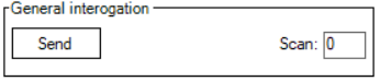
General Interrogation
This function will send telegram Type-identification = 100 (C_IC_NA_1)
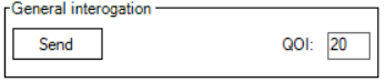
QOI - qualifier of interrogation [0...255]
- 20 - Station interrogation
- 21 - Interrogation of group 1
- 22 - Interrogation of group 2
- 23 - Interrogation of group 3
- 24 - Interrogation of group 4
- 25 - Interrogation of group 5
- 26 - Interrogation of group 6
- 27 - Interrogation of group 7
- 28 - Interrogation of group 8
- 29 - Interrogation of group 9
- 30 - Interrogation of group 10
- 31 - Interrogation of group 11
- 32 - Interrogation of group 12
- 33 - Interrogation of group 13
- 34 - Interrogation of group 14
- 35 - Interrogation of group 15
- 36 - Interrogation of group 16
Counter Interrogation
This function will send telegram Type-identification = 101 (C_CI_NA_1)
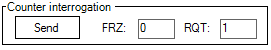
FRZ - freeze[0..3]
- 0 - Station interrogation
- 1 - Interrogation of group 1
- 2 - Interrogation of group 2
- 3 - Interrogation of group 3
RQT - request[0..63]
- 1 - Counter group 1
- 2 - Counter group 2
- 3 - Counter group 3
- 4 - Counter group 3
- 5 - General request
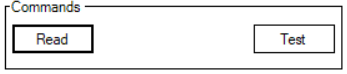
Commands
Read command will send telegram Type-identification = 102 (C_RD_NA_1)
Test command will send telegram Type-identification = 104 (C_TS_NB_1)
Clock synchronization
This function will send telegram Type-identification = 103 (C_CS_NA_1)
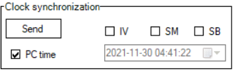
If "PC time" checkbox is checked, then the PC time will be sent. If it's not checked user can set time manually.
Time tag status bits:
- IV - invalid time
- SM - Summer/Winter
- SB - Substitute
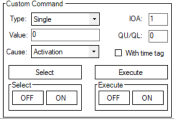
Custom Commands
This function allows user to send commands to the slave device.
Tags
This function allows user to created named points. After points created user can send it manually or set reply checkbox to automatic reply.
There are two ways of creating tags:
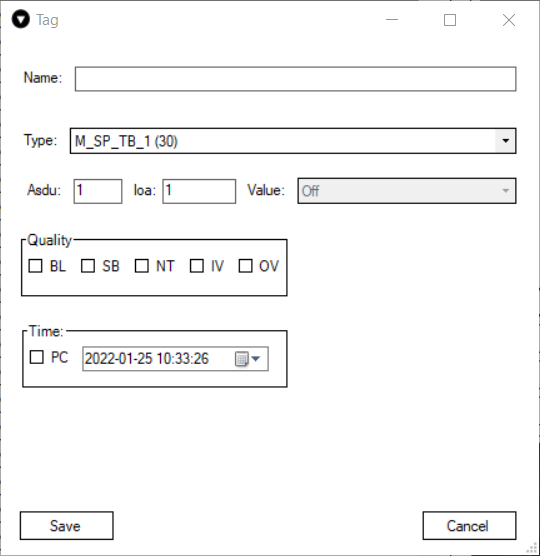
Main parameters:
- Name - user-friendly tag name
- Asdu - Identifier of the device
- Ioa - Identifier of values from the device.
- Type - the type of value.
Here is an example image of the tag window with the M_SP_TB_1 (30) type selected. Each type has different options that can be configured when sending data. For example this type depicted in the picture below can send a value Off or On and it also is time-tagged. The user in this case can either select a specific time that they have in mind or just mark the PC checkbox and The Vinci software will automatically send the current PC time. As you can see the Value box in this example is greyed out that is because this tag is created on a master simulation, and this type doesn't support writing to slave.
Setup
To setup an IEC 60870-5-101 simulation it is fairly straightforward.
1. Select IEC 60870-5-101 and the mode.

2. Select Serial Port settings according to your device specification.
3. Select settings in the settings tab according to your device and preference.
4. Press the green START button and the simulation should start. If everything was done correctly The Vinci software should establish communication with the IEC 60870-5-101 device which you can monitor in the console tab.

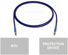
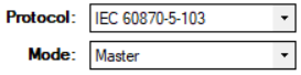
IEC 60870-5-103
IEC 60870-5-103 is a protocol for power system monitoring and controlling. Mostly used for communication between protection devices and devices of a control system in a substation (RTU) over fiber optics.
Info about protocol
Telegram Structure
Telegram format with fixed length
Telegram format with variable length
- RES - Reserved
- PRM - 1 if master, 0 if slave
PRM = 1
- FCB - alternating bit for successive services per station
- FCV - (if FCV=1 FCB enabled)
PRM = 0
- ACD - access demand (if ACD=1 there are class 1 data)
- DFC - data flow control (if DFC=1 further messages may cause data overflow)
Function Code
PRM=1
|
Dec |
Frame type |
Service function |
FCV |
|
0 |
SEND/CONFIRM expected |
Reset of remote link |
0 |
|
1 |
SEND/CONFIRM expected |
Reset of user process |
0 |
|
2 |
SEND/CONFIRM expected |
Reserved |
- |
|
3 |
SEND/CONFIRM expected |
User data |
1 |
|
4 |
SEND/REPLY expected |
User data |
0 |
|
5 |
|
Reserved |
- |
|
6 |
|
Reserved |
- |
|
7 |
|
Reserved |
- |
|
8 |
REQUEST for access demand |
Expected response specifies access demand |
0 |
|
9 |
REQUEST/RESPOND expected |
Request status of link |
0 |
|
10 |
REQUEST/RESPOND expected |
Request user data class 1 |
1 |
|
11 |
REQUEST/RESPOND expected |
Request user data class 2 |
1 |
|
12 |
|
Reserved |
- |
|
13 |
|
Reserved |
- |
|
14 |
|
Reserved |
- |
|
15 |
|
Reserved |
- |
PRM=0
|
Dec |
Frame type |
Service function |
|
0 |
CONFIRM |
ACK: positive acknowledgment |
|
1 |
CONFIRM |
NACK: message not accepted, link busy |
|
2 |
|
Reserved |
|
3 |
|
Reserved |
|
4 |
|
Reserved |
|
5 |
|
Reserved |
|
6 |
|
Reserved |
|
7 |
|
Reserved |
|
8 |
RESPOND |
User data |
|
9 |
RESPOND |
NACK: requested data not available |
|
10 |
|
Request user data class 1 |
|
11 |
RESPOND |
Request user data class 2 |
|
12 |
|
Reserved |
|
13 |
|
Reserved |
|
14 |
|
Reserved |
|
15 |
|
Reserved |
Type identification
Standard IEC 60870-5-103 data types[1-255]
- [1-31] - standard definition
- [32-255] - for special use
|
Dec |
Description |
Direction |
Support |
|
1 |
Time-tagged message |
Monitor |
Yes |
|
2 |
Time-tagged message with relative time |
Monitor |
Yes |
|
3 |
Measurands I |
Monitor |
Yes |
|
4 |
Time-tagged measurands with relative time |
Monitor |
Yes |
|
5 |
Identification |
Monitor |
Yes |
|
6 |
Clock synchronization |
Both |
Yes |
|
7 |
General interrogation |
Control |
Yes |
|
8 |
End of general interrogation |
Monitor |
Yes |
|
9 |
Measurands II |
Monitor |
Yes |
|
10 |
Generic data |
Both |
No |
|
11 |
Generic identification |
Monitor |
No |
|
20 |
General command |
Control |
Yes |
|
21 |
Generic command |
Control |
No |
|
23 |
List of recorded disturbances |
Monitor |
No |
|
24 |
Order for disturbance data transmission |
Control |
No |
|
25 |
Acknowledgment for disturbance data transmission |
Control |
No |
|
26 |
Ready for transmission of disturbance data |
Monitor |
No |
|
27 |
Ready for transmission of a channel |
Monitor |
No |
|
28 |
Ready for transmission of tags |
Monitor |
No |
|
29 |
Transmission of tags |
Monitor |
No |
|
30 |
Transmission of disturbance values |
Monitor |
No |
|
31 |
End of transmission |
Monitor |
No |
Cause of transmission
Standard IEC 60870-5-103 cause of transmission [0-255]
- [0] - not used
- [1-63] - standard definition
- [64-255] - for special use
|
Dec |
Description |
|
1 |
Spontaneous |
|
2 |
Cyclic |
|
3 |
Reset frame count bit ( FCB ) |
|
4 |
Reset communication unit ( CU ) |
|
5 |
Start/ restart |
|
6 |
Power ON |
|
7 |
Test mode |
|
8 |
Time synchronization |
|
9 |
General interrogation |
|
10 |
End of general interrogation |
|
11 |
Return information caused by a remote command |
|
12 |
Return information caused by a local command |
|
20 |
Command "ACK positive" |
|
21 |
Command "ACK negative" |
|
31 |
Transmission disturbance data |
|
40 |
Generic write command with ACK positive |
|
41 |
Generic write command with ACK negative |
|
42 |
Generic read command data valid |
|
43 |
Generic read command data invalid |
|
44 |
Generic write conformation |
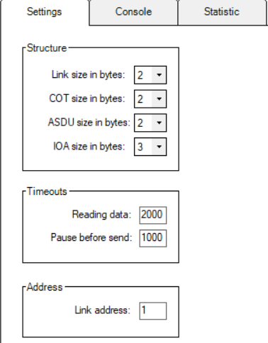
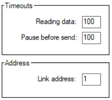
Settings
|
Timeouts (ms) |
||||
|
|
|
Monitor |
Master |
Slave |
|
Reading data |
Waiting data in serial port buffer |
Waiting data in serial port buffer |
Waiting data in serial port buffer |
|
|
Pause before send |
Not used |
Pause before send data |
Pause before send data |
|
|
Address |
||||
|
|
|
Monitor |
Master |
Slave |
|
Link |
Not used |
Remote device address |
Own system address |
|
|
ASDU |
Not used |
Remote device address |
Own system address |
|
|
Commands ack. |
||||
|
|
|
Monitor |
Master |
Slave |
|
Auto ack. system commands |
Not used |
Not used |
Auto acknowledge system commands |
|
|
Auto ack. control commands |
Not used |
Not used |
Auto acknowledge commands |
|

System
For all system functions user can set custom address:

General Interrogation
This function will send telegram Type-identification = 7
Clock synchronization
This function will send telegram Type-identification = 103 (C_CS_NA_1)
If "PC time" checkbox is checked, then the PC time will be sent. If it's not checked user can set time manually.
Time tag status bits:
- IV - invalid time
- SM - Summer/Winter
- SB - Substitute
General Command
This function allows user to send command to slave device.

Tags
This function allows user to created named points. After points created user can send it manually or set reply checkbox to automatic reply.
There are two ways of creating tags:
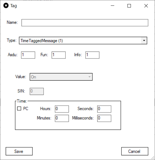
Main parameters:
- Name - user-friendly tag name
- Type - the type of value.
- Asdu - Identifier of the device
- Fun - function number
- Info- Identifier of values from the device.
Here is an example image of the tag window with the TimeTaggedMessage(1) type selected. Each type has different options that can be configured when sending data. For example this type depicted in the picture below can send a value Off or On and it also is time-tagged. The user in this case can either select a specific time that they have in mind or just mark the PC checkbox and The Vinci software will automatically send the current PC time. As you can see the Value box in this example is greyed out that is because this tag is created on a master simulation, and this type doesn't support writing to slave.
Setup
To setup an IEC 60870-5-103 simulation it is fairly straightforward.
1. Select IEC 60870-5-103 and the mode.
2. Select Serial Port settings according to your device specification.
3. Select settings in the settings tab according to your device and preference.
4. Press the green START button and the simulation should start. If everything was done correctly The Vinci software should establish communication with the IEC 60870-5-103 device which you can monitor in the console tab.

IEC 60870-5-104
IEC 60870-5-104 is a protocol for power system monitoring and controlling. Mostly used to communication between substations and control centers over Ethernet (Fiber optics, 2/3/4G, ...).IEC 60870-5-104 protocol is an extension of IEC 60870-5-101 protocol with the changes in transport, network, link and physical layer services to suit the complete network access.
Info about protocol
Telegram Structure
Teleram format with fixed length

Telegram format with variable length
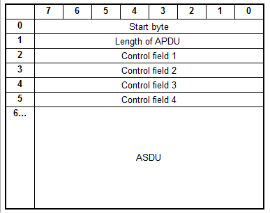
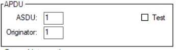
- APCI - Application Protocol Control Information (First 6 bytes)
- APDU - Application Protocol Data Unit (All variable length telegram)
- ASDU - Application Service Data Unit
Type identification
Standard IEC 60870-5-104 data types[1-255]
- [1-127] - standard definition
- [128-135] - reserved for routing of messages
- [136-255] - for special use
|
Dec |
Type |
Description |
Direction |
Support |
|
Process information |
||||
|
1 |
M_SP_NA_1 |
Single-point information |
Monitor |
Yes |
|
2 |
M_SP_TA_1 |
Single-point information with time tag |
Monitor |
Yes |
|
3 |
M_DP_NA_1 |
Double-point information |
Monitor |
Yes |
|
4 |
M_DP_TA_1 |
Double-point information with time tag |
Monitor |
Yes |
|
5 |
M_ST_NA_1 |
Step position information |
Monitor |
Yes |
|
6 |
M_ST_TA_1 |
Step position information with time tag |
Monitor |
Yes |
|
7 |
M_BO_NA_1 |
Bit string of 32 bit |
Monitor |
Yes |
|
8 |
M_BO_TA_1 |
Bit string of 32 bit with time tag |
Monitor |
Yes |
|
9 |
M_ME_NA_1 |
Measured value, normalized value |
Monitor |
Yes |
|
10 |
M_ME_TA_1 |
Measured value, normalized value with time tag |
Monitor |
Yes |
|
11 |
M_ME_NB_1 |
Measured value, scaled value |
Monitor |
Yes |
|
12 |
M_ME_TB_1 |
Measured value, scaled value wit time tag |
Monitor |
Yes |
|
13 |
M_ME_NC_1 |
Measured value, short floating point number |
Monitor |
Yes |
|
14 |
M_ME_TC_1 |
Measured value, short floating point number with time tag |
Monitor |
Yes |
|
15 |
M_IT_NA_1 |
Integrated totals |
Monitor |
Yes |
|
16 |
M_IT_TA_1 |
Integrated totals with time tag |
Monitor |
Yes |
|
17 |
M_EP_TA_1 |
Event of protection equipment with time tag |
Monitor |
Yes |
|
18 |
M_EP_TB_1 |
Packed start events of protection equipment with time tag |
Monitor |
Yes |
|
19 |
M_EP_TC_1 |
Packed output circuit information of protection equipment with time tag |
Monitor |
Yes |
|
20 |
M_PS_NA_1 |
Packed single point information with status change detection |
Monitor |
Yes |
|
21 |
M_ME_ND_1 |
Measured value, normalized value without quality descriptor |
Monitor |
Yes |
|
30 |
M_SP_TB_1 |
Single-point information with time tag CP56Time2a |
Monitor |
Yes |
|
31 |
M_DP_TB_1 |
Double-point information with time tag CP56Time2a |
Monitor |
Yes |
|
32 |
M_ST_TB_1 |
Step position information with time tag CP56Time2a |
Monitor |
Yes |
|
33 |
M_BO_TB_1 |
Bit string of 32 bit with time tag CP56Time2a |
Monitor |
Yes |
|
34 |
M_ME_TD_1 |
Measured value, normalized value with time tag CP56Time2a |
Monitor |
Yes |
|
35 |
M_ME_TE_1 |
Measured value, scaled value with time tag CP56Time2a |
Monitor |
Yes |
|
36 |
M_ME_TF_1 |
Measured value, short floating point number with time tag CP56Time2a |
Monitor |
Yes |
|
37 |
M_IT_TB_1 |
Integrated totals with time tag CP56Time2a |
Monitor |
Yes |
|
38 |
M_EP_TD_1 |
Event of protection equipment with time tag CP56Time2a |
Monitor |
Yes |
|
39 |
M_EP_TE_1 |
Packed start events of protection equipment with time tag CP56Time2a |
Monitor |
Yes |
|
40 |
M_EP_TF_1 |
Packed output circuit information of protection equipment with time tag CP56Time2a |
Monitor |
Yes |
|
45 |
C_SC_NA_1 |
Single command |
Control |
Yes |
|
46 |
C_DC_NA_1 |
Double command |
Control |
Yes |
|
47 |
C_RC_NA_1 |
Regulating step command |
Control |
Yes |
|
48 |
C_SE_NA_1 |
Set-point Command, normalized value |
Control |
Yes |
|
49 |
C_SE_NB_1 |
Set-point Command, scaled value |
Control |
Yes |
|
50 |
C_SE_NC_1 |
Set-point Command, short floating point number |
Control |
Yes |
|
51 |
C_BO_NA_1 |
Bit string 32 bit command |
Control |
Yes |
|
58 |
C_SC_TA_1 |
Single command with time tag CP56Time2a |
Control |
Yes |
|
59 |
C_DC_TA_1 |
Double command with time tag CP56Time2a |
Control |
Yes |
|
60 |
C_RC_TA_1 |
Regulating step command with time tag CP56Time2a |
Control |
Yes |
|
61 |
C_SE_TA_1 |
Measured value, normalized value command with time tag CP56Time2a |
Control |
Yes |
|
62 |
C_SE_TB_1 |
Measured value, scaled value command with time tag CP56Time2a |
Control |
Yes |
|
63 |
C_SE_TC_1 |
Measured value, short floating point number command with time tag CP56Time2a |
Control |
Yes |
|
64 |
C_BO_TA_1 |
Bit string of 32 bit command with time tag CP56Time2a |
Control |
Yes |
|
System information |
||||
|
70 |
M_EI_NA_1 |
End of Initialization |
Monitor |
Yes |
|
100 |
C_IC_NA_1 |
Interrogation command |
Control |
Yes |
|
101 |
C_CI_NA_1 |
Counter interrogation command |
Control |
Yes |
|
102 |
C_RD_NA_1 |
Read command |
Control |
Yes |
|
103 |
C_CS_NA_1 |
Clock synchronization command |
Control |
Yes |
|
104 |
C_TS_NA_1 |
Test command |
Control |
Yes |
|
105 |
C_RP_NA_1 |
Reset process command |
Control |
Yes |
|
106 |
C_CD_NA_1 |
Delay acquisition command |
Control |
No |
|
107 |
C_TS_TA_1 |
Test command with time tag CP56Time2a |
Control |
No |
|
Parameter |
||||
|
110 |
P_ME_NA_1 |
Parameter of measured values, normalized value |
Control |
No |
|
111 |
P_ME_NB_1 |
Parameter of measured values, scaled value |
Control |
No |
|
112 |
P_ME_NC_1 |
Parameter of measured values, short floating point number |
Control |
No |
|
113 |
P_AC_NA_1 |
Parameter activation |
Control |
No |
|
File transfer |
||||
|
120 |
F_FR_NA_1 |
File ready |
File transfer |
No |
|
121 |
F_SR_NA_1 |
Section ready |
File transfer |
No |
|
122 |
F_SC_NA_1 |
Call directory, select file, call file, call section |
File transfer |
No |
|
123 |
F_LS_NA_1 |
Last section, last segment |
File transfer |
No |
|
124 |
F_FA_NA_1 |
ACK file, ACK section |
File transfer |
No |
|
125 |
F_SG_NA_1 |
Segment |
File transfer |
No |
|
126 |
F_DR_TA_1 |
Directory |
File transfer |
No |
|
127 |
F_SC_NB_1 |
Request archive file |
File transfer |
No |
Cause of transmission
Standard IEC 60870-5-101 cause of transmission [0-63]
|
Dec |
Description |
|
1 |
Periodic, cyclic |
|
2 |
Background interrogation |
|
3 |
Spontaneous |
|
4 |
Initialized |
|
5 |
Interrogation or interrogated |
|
6 |
Activation |
|
7 |
Confirmation activation |
|
8 |
Deactivation |
|
9 |
Confirmation deactivation |
|
10 |
Termination activation |
|
11 |
Return information caused by a remote command |
|
12 |
Return information caused by a local command |
|
13 |
File transfer |
|
20 |
Interrogated by general interrogation |
|
21 |
Interrogated by interrogation group 1 |
|
22 |
Interrogated by interrogation group 2 |
|
23 |
Interrogated by interrogation group 3 |
|
24 |
Interrogated by interrogation group 4 |
|
25 |
Interrogated by interrogation group 5 |
|
26 |
Interrogated by interrogation group 6 |
|
27 |
Interrogated by interrogation group 7 |
|
28 |
Interrogated by interrogation group 8 |
|
29 |
Interrogated by interrogation group 9 |
|
30 |
Interrogated by interrogation group 10 |
|
31 |
Interrogated by interrogation group 11 |
|
32 |
Interrogated by interrogation group 12 |
|
33 |
Interrogated by interrogation group 13 |
|
34 |
Interrogated by interrogation group 14 |
|
35 |
Interrogated by interrogation group 15 |
|
36 |
Interrogated by interrogation group 16 |
|
37 |
Interrogated by counter general interrogation |
|
38 |
Interrogated by interrogation counter group 1 |
|
39 |
Interrogated by interrogation counter group 2 |
|
40 |
Interrogated by interrogation counter group 3 |
|
41 |
Interrogated by interrogation counter group 4 |
|
44 |
Type Identification unknown |
|
45 |
Cause unknown |
|
46 |
ASDU address unknown |
|
47 |
Information object address unknown |
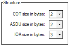
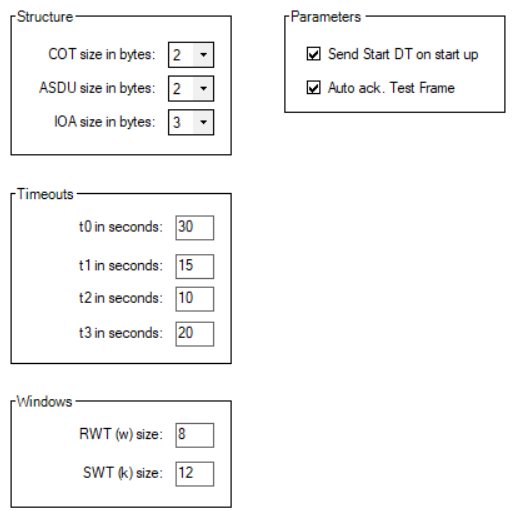
Settings
|
Structure |
|||
|
|
|
Master, Slave, Monitor | |
|
COT size in bytes |
COT size in bytes |
||
|
ASDU size in bytes |
ASDU size in bytes |
||
|
IOA size in bytes |
IOA size in bytes |
||
|
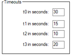
Timeouts (ms) |
|||
|
|
|
Master |
Slave |
|
t0 in seconds |
Timeout for the establishment of the connection with the server. |
Not used |
|
|
t1 in seconds |
This parameter defines the time in seconds that Master waits maximum for an acknowledge from the slave. |
This parameter defines the time in seconds that slave waits maximum for an acknowledge from the master. |
|
|
t2 in seconds |
A S-format frame will be sent at the latest after this time starting from the last received telegram from the slave. |
A S-format frame will be sent at the latest after this time starting from the last received telegram from the master. |
|
|
t3 in seconds |
A Test frame will be sent at the latest after this time starting from the last received telegram from the slave. |
A Test frame will be sent at the latest after this time starting from the last received telegram from the master |
|
|
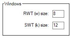
Windows |
|||
|
|
|
Master |
Slave |
|
w size |
This parameter indicates the number of received I frames after the S-Frame will be send. |
This parameter indicates the number of received I frames after the S-Frame will be send |
|
|
k size |
Maximum I-frames send until acknowledgment. |
Not used |
|
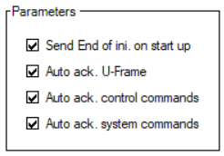
| SLAVE Parameters | |||
|
|
|
Slave |
|
|
Send End of ini. on start up |
Send end of initialization TI 70 (M_EI_NA_1) |
||
|
Auto ack. U-Frame |
Auto ack. U-Frame. |
||
|
Auto ack. control commands |
Auto acknowledge commands |
||
|
Auto ack. system commands |
Auto acknowledge system commands (TI: 100, 103) |
||
|
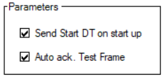
MASTER Parameters |
|||
|
|
|
Master |
|
|
Send Start DT on start up |
Send Start DT on startup |
||
|
Auto ack. Test Frame |
Auto ack. Test frame |
||
System
For all system functions user can set custom address:
General Interrogation
This function will send telegram Type-identification = 100 (C_IC_NA_1)
QOI - qualifier of interrogation [0...255]
- 20 - Station interrogation
- 21 - Interrogation of group 1
- 22 - Interrogation of group 2
- 23 - Interrogation of group 3
- 24 - Interrogation of group 4
- 25 - Interrogation of group 5
- 26 - Interrogation of group 6
- 27 - Interrogation of group 7
- 28 - Interrogation of group 8
- 29 - Interrogation of group 9
- 30 - Interrogation of group 10
- 31 - Interrogation of group 11
- 32 - Interrogation of group 12
- 33 - Interrogation of group 13
- 34 - Interrogation of group 14
- 35 - Interrogation of group 15
- 36 - Interrogation of group 16
Counter Interrogation
This function will send telegram Type-identification = 101 (C_CI_NA_1)
FRZ - freeze[0..3]
- 0 - Station interrogation
- 1 - Interrogation of group 1
- 2 - Interrogation of group 2
- 3 - Interrogation of group 3
RQT - request[0..63]
- 1 - Counter group 1
- 2 - Counter group 2
- 3 - Counter group 3
- 4 - Counter group 3
- 5 - General request
Commands
Read command will send telegram Type-identification = 102 (C_RD_NA_1)
Test command will send telegram Type-identification = 104 (C_TS_NB_1)
Clock synchronization
This function will send telegram Type-identification = 103 (C_CS_NA_1)
If "PC time" checkbox is checked, then the PC time will be sent. If it's not checked user can set time manually.
Time tag status bits:
- IV - invalid time
- SM - Summer/Winter
- SB - Substitute
Custom Commands
This function allows user to send commands to the slave device.
Channel
With these functions a user has the ability to send any U or S frame telegram.
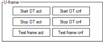
- Start DT act - Send Start Data terminal activation
- Start DT cnf - Send Start Data terminal confirmation
- Stop DT act - Send Stop Data terminal activation
- Stop DT cnf - Send Stop Data terminal confirmation
- Test Frm act - Send Test Frame activation
- Test Frm cnf - Send Test Frame confirmation
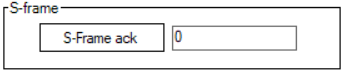
S-Frame ack - Send S-Frame. User can specify acknowledgment telegram count in text box.
Tags
This function allows user to created named points. After points created user can send it manually or set reply checkbox to automatic reply.
There are two ways of creating tags:
Main parameters:
- Name - user-friendly tag name
- Asdu - Identifier of the device
- Ioa - Identifier of values from the device.
- Type - the type of value.
Here is an example image of the tag window with the M_SP_TB_1 (30) type selected. Each type has different options that can be configured when sending data. For example this type depicted in the picture below can send a value Off or On and it also is time-tagged. The user in this case can either select a specific time that they have in mind or just mark the PC checkbox and The Vinci software will automatically send the current PC time. As you can see the Value box in this example is greyed out that is because this tag is created on a master simulation, and this type doesn't support writing to slave.
Setup
To setup an IEC 60870-5-104 simulation it is fairly straightforward.
1. Select IEC 60870-5-104 and the mode.

2. Select Ethernet settings to connect to device. Set the IP and the Port. (Default port: 2404)

3. Select settings in the settings tab according to your device and preference.
4. Press the green START button and the simulation should start. If everything was done correctly The Vinci software should establish communication with the IEC 60870-5-104 device which you can monitor in the console tab.