General
Introduction
Vinci protocol analyzer is an industrial communication tool for commissioning engineers and developers to simulate, analyze and test communication systems that use the IEC 60870-5 and Modbus protocols. With this software, you can monitor the communication channel - see what the master asks and what slaves answer. This makes it easier to diagnose and resolve communication issues between master and slave nodes in an industrial environment when troubleshooting or developing industrial applications and equipment.

What can it do?
You can use one of three operational modes: Master simulation, Slave simulation and Monitor mode. With each of these protocols, you can see how the communication is happening between each device and simulate them in your own specific way.
Master simulation gives the ability to simulate a master device for your slaves. You can use it to resolve remote problems with your SCADA systems or test a slave device before entering it into production.
Slave simulation gives the ability to simulate one or more slave devices, that way you can test out your SCADA system with specific data, or load.
Monitor mode is used when you need to see what is happening between the master and slave. It intercepts the data and gives you the ability to monitor the communication in an easy, readable format.
| IEC-60870-5-101 | Master |
| Slave | |
| Monitor | |
| IEC-60870-5-103 | Master |
| Slave | |
| Monitor | |
| IEC-60870-5-104 | Master |
| Slave | |
| Monitor | |
| Modbus (TCP, RTU, ASCII) | Master |
| Slave | |
| Monitor | |
| Serial port | Monitor |
Example use cases
For example, you can use Vinci to simulate a connection between a PLC and an HMI from your project. This is much easier than purchasing or installing both devices, and it’s a great way to troubleshoot your communication before you get stuck with real industrial equipment. You can also use Vinci for network monitoring of SCADA systems—it works with both MODBUS and IEC60870-5 protocols.
Quick-Start Guide
Vinci Hardware
Software Installation
The software can be downloaded from this link. After downloading the .exe installation file run it. The setup will open.
- To install The Vinci Software accept the license agreement and click next.
- Select Installation Destination Location and click Next.
- Select Start Menu Folder and click next.
- Choose whether to create a desktop shortcut
First Startup
Once the Vinci program is installed go to the install directory and open the Vinci application. A similar window as to the one below should open.
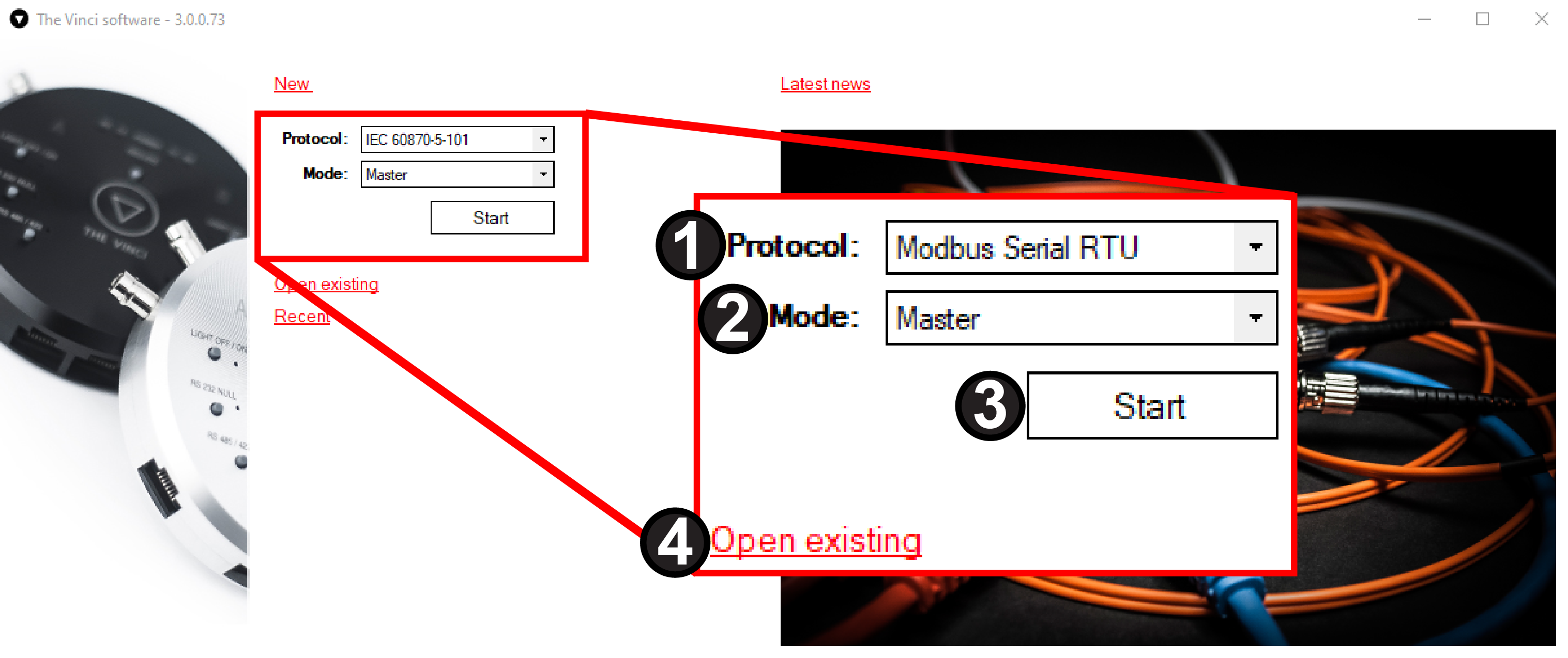
- Protocol selection :
- IEC 60870-5-101
- IEC 60870-5-103
- IEC 60870-5-104
- Modbus Serial RTU
- Modbus Serial ASCII
- Modbus TCP
- SerialPort
- Mode selection :
- Master
- Slave
- Monitor
- Start button to load configuration once selected.
- Open existing configuration file from the previous session.
Protocol specifics can be found here
After selecting the desired protocol pressing the start button will begin a new Vinci session and open a new file explorer prompt. There you can choose a save location and change the name of the file. After setting up the session this file will be saved automatically when you exit, so there is a possibility to save protocol configurations for future use. These configurations can be opened later by pressing the Open existing button on the app.
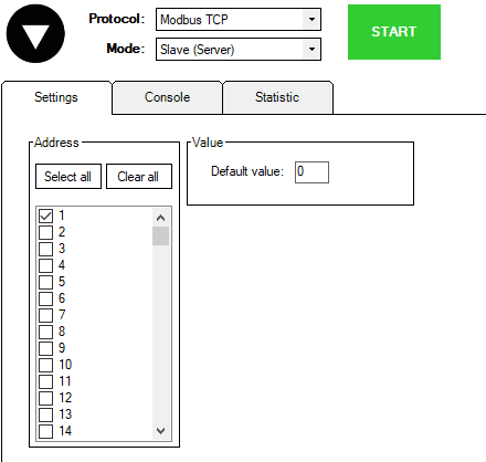
Depending on the protocol you chose a window similar to the one depicted below should open. (In this scenario it is a Modbus TCP Master session )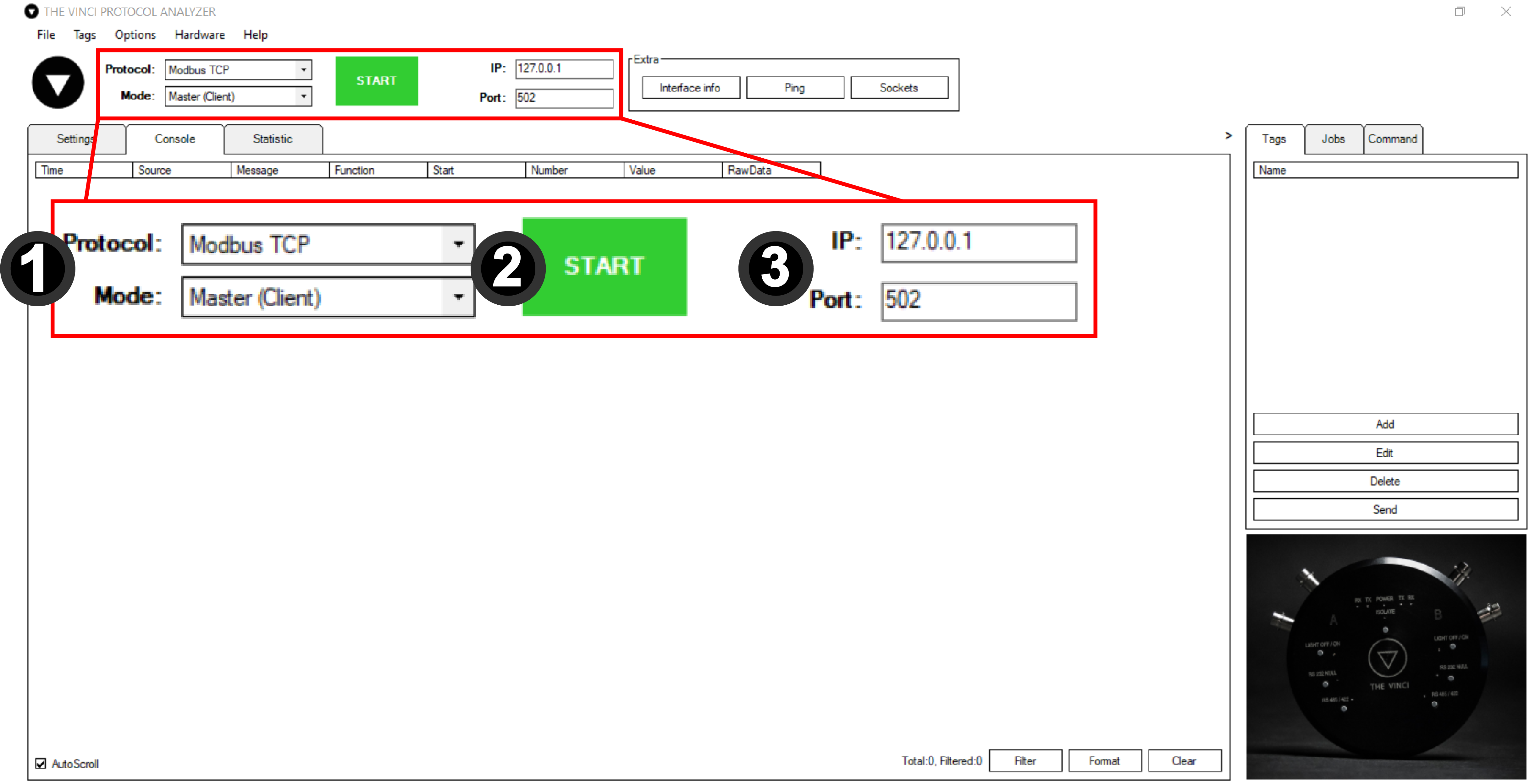
- Protocol selection and Mode selection like before.
- Start button to begin communication with the specified device.
- Interface Selection. Depending on the protocol this can either be IP and Port or Serial connection parameters.
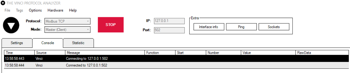
After configuring the interface pressing the start button should establish a connection to the specified interface. If the device is a Modbus TCP device.
Now depending on the selected protocol Jobs, Tags and Commands can be configured.
To find more information on how to configure specific protocols click here
To find more information about the user interface click here
User Interface
Menu Bar
File
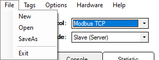
- New - Create new .vinci file.
- Open - Open existing .vinci file.
- SaveAs - Save current file with a different name.
- Exit - Close the program.
Tags
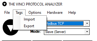
- Import - import previously saved .csv file.
- Export - export currently configured Tags to a .csv file.
To get more information about how tags work click here
Options
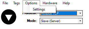
- Settings - opens settings window as depicted below.
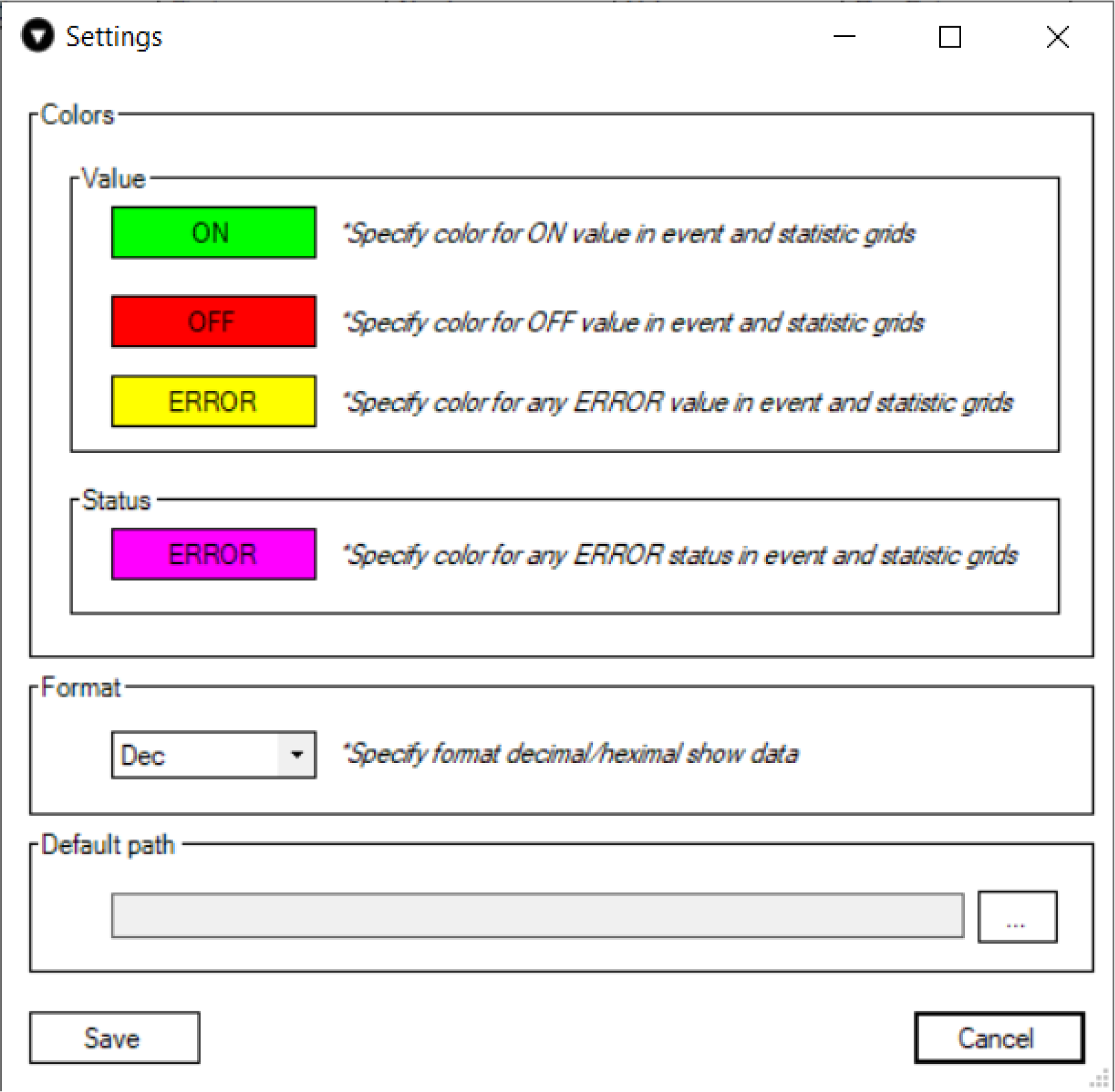
In this window you can choose:
- The colors that appear in the statistics menu.
- The format to show data. (Decimal or Hexadecimal)
- Default path to save session configuration.
Hardware
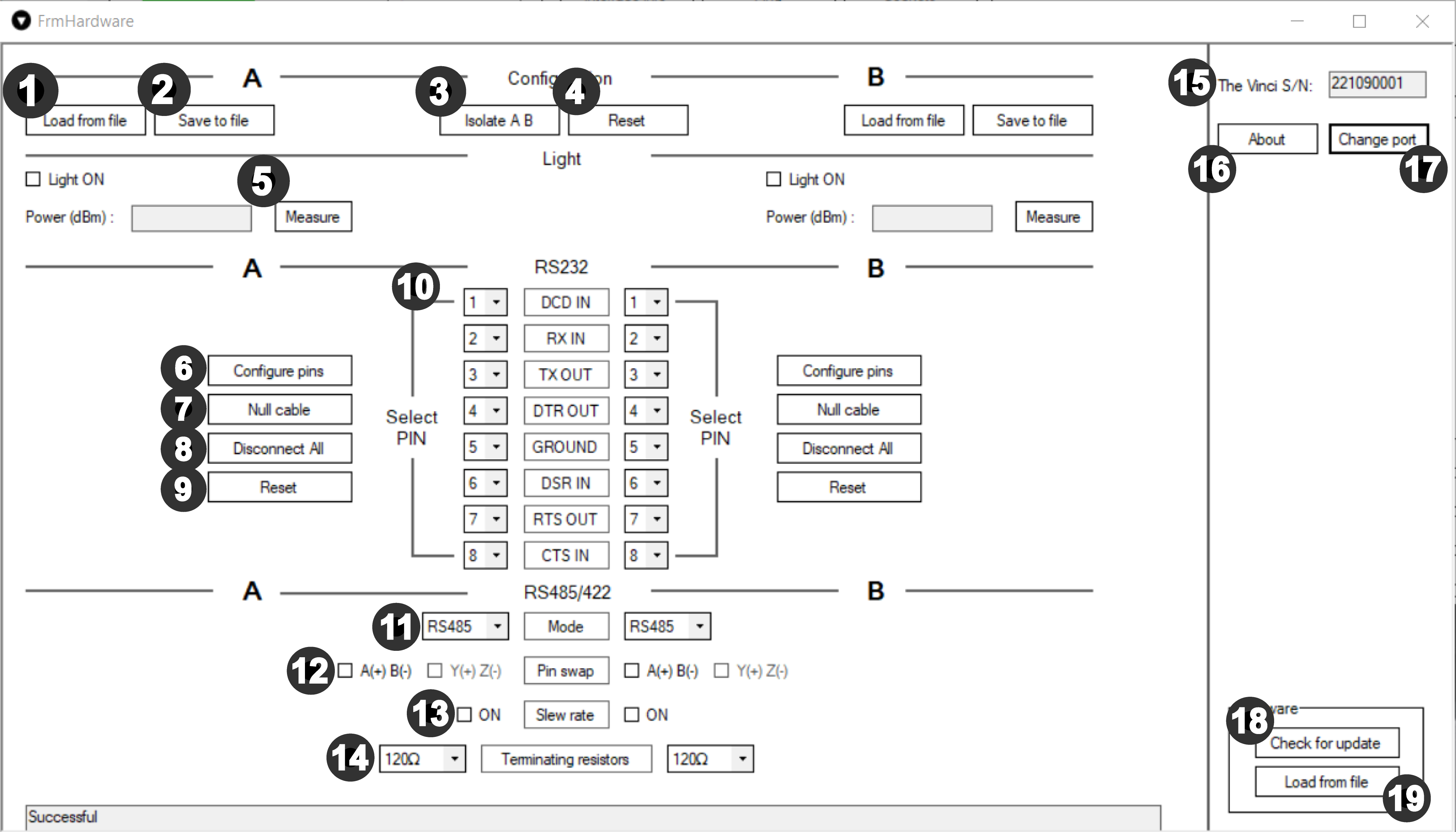
The Vinci Expert device must be connected for this tab to work.
All of the settings are for A and B sides respectively except 3,4,15,16,17,18,19.
In this tab, The Vinci Expert device configuration may be changed.
- Load from file - Configuration can be loaded for A and B side separately.
- Save to file - Save hardware configuration for further use.
- Isolate A B - by clicking this button isolation of The Vinci can be changed. It has the same functionality as the physical Isolate button.
- Non isolated
- The Vinci works like analyser/proble. Everything that comes to A side, comes out of B side and in reverse - what comes in B side goes to A side.
- Isolated
-
By pressing "Isolate A B" button, it isolates serial interface A side from B side. That means Vinci works like protocol master / slave. Everything that comes to A side, comes out of A side and in reverse – what comes in B side, goes out of B side.
-
- Non isolated
- Reset - The Vinci Expert resets to default settings.
- All previous settings, including software-defined, will be set to defaults.
- When the reset button is activated all lights flash clockwise once and the power indicator stays green.
- When the Vinci is programmed by software, the power indicator stays red.
-
Convert Fiber Optical channel from Light Off mode to Light On mode for A and B side separately.
Measure - press this button to measure Light signal power in (dBm). 820nm is nominal wavelength.
- Configure pins - The Vinci Expert connects pins like in the specified configuration. (Configuration at 10)
- Null cable - by pressing this button you can switch modem cable mode to null.
- Disconnect All - disconnects all pin from connector.
- Reset - the pins will be reset to default RS232 pin sequence.
- Here RJ-45 pins can be assigned with RS232 signals for both A and B sides separately
- Mode - Selection between RS485 and RS422 serial interface.
- Pin swap - in RS485 A(+)B(-) differential pair can be swapped. Using RS422 mode, A(+)B(-) and Y(+)Z(-) differential pairs can be swapped respectively.
- Slew rate - slower slew rate can be enabled.
- Terminating resistors - selectable 100 Ohm, 120 Ohm or no termination resistor RT on RS485 and RS422.
- The serial number of the connected the Vinci device.
- About - more information about The Vinci Expert device, incl. serial number and Firmware version.
- Change Port - change the control port of the The Vinci Expert device. Used when several The Vinci Expert devices are used.
- Check for update - automatically updates The Vinci Expert firmware version.
- Load from file - firmware can be updated from file.
Help
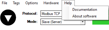
- Documentation - links to the wiki.
- About software - information about software and terms and conditions.
Settings
Protocol specific settings for the simulated device.
Protocol specifics can be found here
Console

Console log of all messages recieved and sent.
Statistic
In this tab you can see all the signal values that the Vinci Software has read from the configured device. In this example you can see values read from 8DI8DO IOMod after general interrogation

Filter and Formatting
Placement
Filter and Format buttons can be found at the bottom right side of the Console window, as demonstrated in the picture below

Filter
Filtering refers to comparing a list of records against specific criteria and then hiding the records that don’t match the criteria. It can be used simply to help find a record, or to create a subset of data that you can then format and copy without affecting the other records.
In the console window, you can filter the log messages by certain parameters of a protocol. To set up a filter you press the Filter button and select wanted options that are specific to the chosen protocol. The options are explained in their specific protocol page.
Only 2 main boxes are persistent thriought all protocols:
- Enabled - toggle if you want to enable the filter.
- Show system messages - toggle to filter out system messages. E.g. "Can't open serial port: COMx"
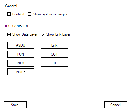
If the filter is enabled, the button will appear red.

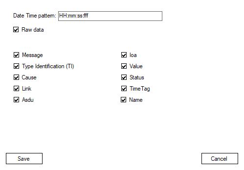
Formatting
Formatting refers to changing how data is displayed to the user. You can edit how much data is shown, what type of fields you want to see, how the date should be displayed. All the format options besides date time are specific to the chosen protocol.
Tags
Slave:
Master:
All tags are protocol-specific.