The Vinci Expert
This page covers all documentations about The Vinci Expert (hardware) technical specifications, use cases, manuals, tips, and tricks, and others.
- Overview
- Features
- Functionality
- Non Isolated Mode Examples
- Isolated Mode Examples
- Technical Data
- Application Note
- Connection To PC
- Benefits of Using Software
- Complectation
- Notes
Overview
THE VINCI EXPERT is the best choice for applications requiring the highest versatility of physical serial communication interfaces. Commissioning engineers, system integrators and product developers will especially appreciate the possibility to perform wiring and plausibility checks of serial interface wires and convert physical interface from one to another.
• Lightweight anodized 6-series Aluminum alloy body
• Magnetic bottom side which sticks on metal surfaces
• Semi-soft case which includes all necessary adapters and wires
• Auto-save setting function
• Through-software setting management
• Fiber optics power measurement
• Custom RS232 pinout configuration. 8x8 pin selection.
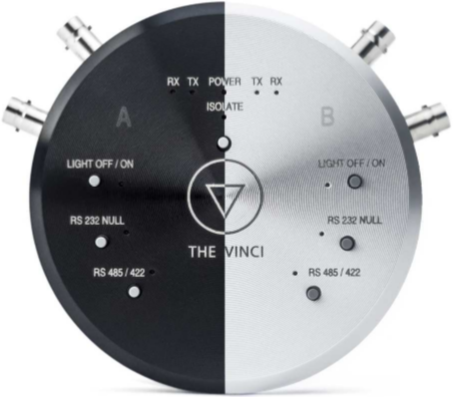
Features
Front face Back face
Power on indicator. Side A
Default / Custom settings indicator.
Fiber optic A Multi-mode Fiber Media Optic
Isolate indicator. TX A Fiber Media Optic TX port.
Light OFF/ON light on indicator. RX A Fiber Media Optic RX port.
RS 232 NULL null modem indicator. RS232 A Serial interface RS232 Side A.
RS 485/422 selection indicator. RS485/422 A Serial interface Side A.
Side B
Fiber optic B Multi-mode Fiber Media Optic
TX B Fiber Media Optic TX port.
RX B Fiber Media Optic RX port.
RS232 B Serial interface RS232 Side B.
RS485/422 B Serial interface Side B
Functionality
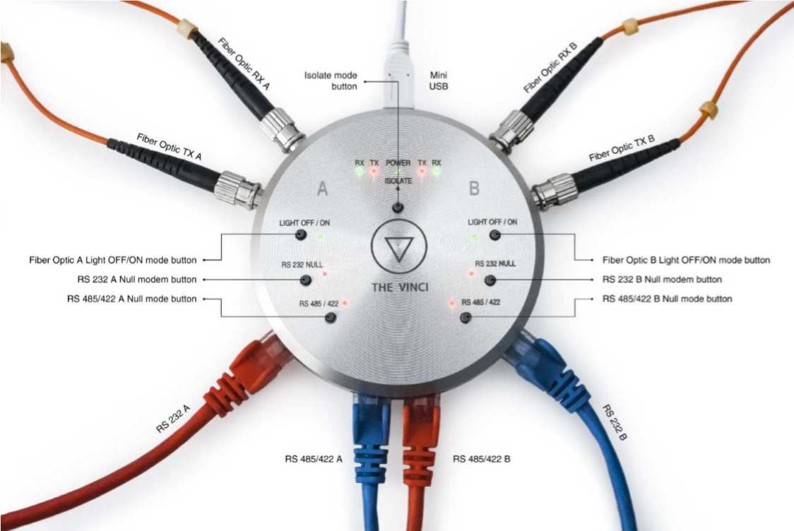
Fiber Optic LIGHT ON/OFF mode button – by pressing this button you can easily convert Fiber Optical channel from Light Off mode to Light On mode. The Light On mode is indicated by a Light On indicator. Fiber optic power can be measured in software.
![]() Laser radiation hazard. Avoid eye exposure to direct or scattered radiation
Laser radiation hazard. Avoid eye exposure to direct or scattered radiation
ISOLATE button – (1) by pressing this button once you can isolate serial interface A side from B side. That means THE VINCI EXPERT works like protocol master / slave. Everything that comes to A side, comes out of A side and in reverse – what comes in B side, goes to B side.
(2) by holding this button for 4 seconds, THE VINCI EXPERT resets to default settings. This means all previous settings, including software defined, will be set to defaults. When defaults is activated all buttons flashes clockwise once and power indication stays green. When custom configuration is applied through THE VINCI SOFTWARE, power indication stays red.
RS485/422 button - by pressing this button you can switch from RS485 to RS422 mode. When RS422 mode is activated it will be indicated by a RS485/422 indicator. Both interfaces supports baud rates up to 115200.
For custom settings configuration you can use THE VINCI SOFTWARE, which allows you to:
• Enable / disable Termination resistors
• Select termination resistor: 100 or 120 ohm.
• Invert Y Z lines; Invert A B lines;
• Enable / Disable Slew rate.*
*feature reduced slew-rate drivers that minimize EMI and reduce reflections caused by improperly terminated cables, allowing error-free data transmission up to 500kbps.
RS485/422 pinout table:
| RJ-45 PIN | Default | INVERTED | RS485 mode differential pair function | RS422 mode differential pair function |
| 1 | A | B | RX/TX | RX |
| 2 | B | A | RX/TX | RX |
| 3 | - | - | - | - |
| 4 | GND | GND | GND | - |
| 5 | GND | GND | GND | - |
| 6 | - | - | - | - |
| 7 | Y | Z | - | TX |
| 8 | Z | Y | - | TX |
For custom settings configuration you can use THE VINCI SOFTWARE, which allows you to:
• Select Custom pinout for A and B side
• Save/Load settings file in computer
• Full control of THE VINCI EXPERT settings.
RS232 pinout table:
| RJ-45 PIN | Custom MODE | Default MODE (DTE) | RS232 NULL MODE (DCE) |
| 1 | x | DCD (INPUT) | DCD (INPUT) |
| 2 | x | RX (INPUT) | TX (OUTPUT) |
| 3 | x | TX (OUTPUT) | RX (INPUT) |
| 4 | x | DTR (OUTPUT) | DSR (INPUT) |
| 5 | x | GND | GND |
| 6 | x | DSR (INPUT) | DTR (OUTPUT) |
| 7 | x | RTS (OUTPUT) | CTS (INPUT) |
| 8 | x | CTS (INPUT) | RTS (OUTPUT) |
Non Isolated Mode Examples
In this mode, THE VINCI EXPERT works like analyzer / probe. Everything that comes to A side, comes out of B side and in reverse – what comes in B side, goes to A side.

Fig.1.2.
In this example, THE VINCI SOFTWARE works as master
and device connected to THE VINCI EXPERT works as slave.
They are connected in different ports (eg. Software uses A side, device uses B side).
Fig.1.3.
Also, this could be connected in reverse, as THE VINCI SOFTWARE works in slave mode and Device works in master mode.
Fig.1.4.
In this example, THE VINCI SOFTWARE works
as monitor and analyzes serial messages sent through it.
Devices are connected to THE VINCI EXPERT in opposite ports.
Isolated Mode Examples
In this mode, THE VINCI EXPERT works as protocol master / slave. Everything that comes to A side, comes out of A side and in reverse – what comes in B side, goes to B side. A side is isolated from B side.
 Fig.1.5.
Now, there is two instances of THE VINCI SOFTWARE running and two devices are connected to different sides. Each side is working independently.

Fig.1.6.
Here THE VINCI EXPERT is connected to two separate pairs of devices
and THE VINCI SOFTWARE is monitoring and analyzing data on A and B sides.
Technical Data
 Fig.1.7.
| General | |
| Dimensions | D91 x 19.6 mm |
| Case | 6-seriesAluminum |
| Weight | 138g |
| PC USB Connection | Mini USB |
| Electrical characteristics | |
| Power supply | via USB 5V |
| Max. operating current | Imax=460mA |
| Min. operating current | Imin=360mA |
| Warranty | 2 years |
Application Note
THE VINCI EXPERT can be used in two different modes: Isolated and Non-Isolated.
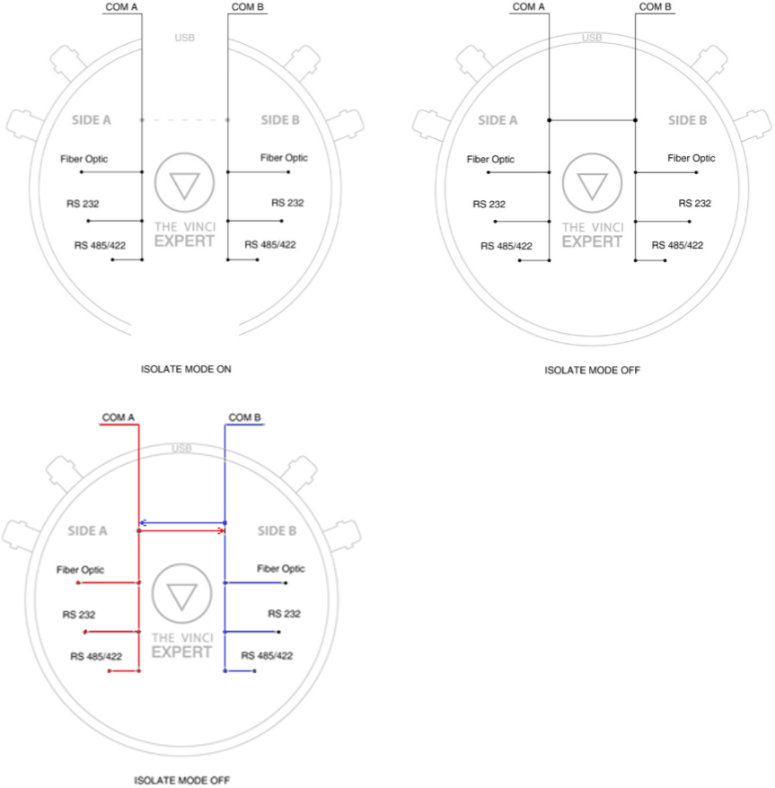 Fig.1.1
• Isolated mode allows user to virtually split device into two, and then use each side separately. This mode is useful when user communicates with devices separately and simultaneously.
• Non-isolated mode crosses A and B side communication. When user puts data into side A, THE VINCI EXPERT will transmit data from side B and in reverse. This mode is useful when user wants to interfere in communication line.
Connection To PC
When you connect THE VINCI EXPERT to a computer a normally operating system in hardware should find 4 Virtual Com Ports (VCP). First Com port for communication with SIDE A and Second for communication with SIDE B, as described in the Function scheme. Other VCP’s are reserved. All serial interfaces RS232, RS485 and Fiber Optic supports baud rates up to 115200 bps.
The drivers of newer versions of Windows (starting from Windows XP), Linux and Mac OS are detected automatically; if you use older versions or other type of OS, please visit our webpage: www.the-vinci.com
Benefits of Using Software
• Easily change settings through software;
• Measure laser power;
• Change RS232 pinout;
• Save settings to a file;
• Analyze protocols and monitor data;
• Upload new firmware into THE VINCI EXPERT device.
Complectation
• THE VINCI EXPERT - serial interface protocol analyzer and universal serial interface converter.
• Hard case with figure cut foam for connectors and a pocket for wires.
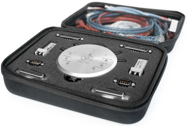 All possible connections and wires are attached:
• 2 x 1 meter long cable RJ-45 to RJ-45
• 2 x Adapters RJ-45 to DB-9 F
• 2 x DB-9 M to DB-9 M
• 2 x DB-9 M to DB-25 F
• 2 x DB-25 M to DB-25 M
• Duplex Multimode Fiber Optical cable with ST to ST connectors
• Mini USB to USB Type A Cable
• Mini power adapter (AC plug) to USB
• 2 x 0.5 meter long RJ-45 cable with loose crimped ends for RS485
• 4GB flash with user manual and software
Notes
Copyrights and trademarks
Elseta is UAB “Elseta” trademark that identifies UAB “Elseta” manufactured products. All of the products copyright belongs to "Elseta”. These documents and the product properties can not be changed without company “Elseta'” knowledge and written consent. User manual may be modified by company “Elseta'” without additional notice.
Declaration of Conformity
(in accordance with ISO / IEC Guide 22 and EN Section 45014)
Manufacturer: UAB “Elseta”
Address of the manufacturer L. Zamenhofo st. 5 LT Vilnius, Lithuania
We claim that:
The Vinci Expert
Conforms to the following standards:
EMC: Radiation EN 55022 (Class A)
1 emitted radiation (30-1000MHz)
Second radiation conductors (0.15-30MHz)
EN 50082-1 immunity test
1 IEC 801-3: Radio-frequency electromagnetic field
2 IEC 801-2: Electrostatic discharge.
3 IEC 801-4: Quick periodic electrostatic discharges
Additional information:
The device complies with the Low Voltage Directive 73/23 / EEC and EMC Directive 89/336 / EEC. Device assembly complies with the RoHS Directive.
Manufacturer contact:
Equipment quality controller
UAB “Elseta”
Address: L. Zamenhofo st. 5, LT 06332, Vilnius, Lithuania
Phone: +370 5 2032302
Email: support@elseta.com
SAFETY REQUIREMENTS
This equipment operating notes, which must be met for your personal safety, as well as to avoid damage to the equipment. These notes are marked with a warning triangle symbol and the various degrees of risk of falling within signs. All work related to electronic systems design, installation, commissioning, adjustment and maintenance should be carried out in accordance with the safety requirements.
EQUIPMENT‘S MANUAL USES SYMBOLS
![]()
Danger - important notice, which may affect the safety of the user or device.![]()
Attention - notice on possible problems that may arise in individual cases.
![]()
Information Notice - the information that is useful advice or special places.
![]()
Warning of the danger. The work may be performed only by a qualified professional. Equipment installation, commissioning and maintenance may only be performed by a qualified professional. If the safety notes in this manual, the term refers to persons qualified specialists authorized to perform commissioning, grounding and labeling devices, systems and circuits. The person must: Be aware of occupational safety in the workplace. Need to understand the equipment components. Electrical equipment. Have the knowledge and skills to identify a component beneath the voltage.![]()
To maintain the equipment necessary to always turn off the power supply before installing or dismantling works. It must be in mind that even though alone equipment, but can have a common ground connection. Always before connecting the power supply, cables and interconnect components must be inspected.![]()
This product can not be implemented, or resold to install in areas that are high-security as nuclear power plants, aircraft navigation, military equipment, transport traffic in management. In areas where equipment failure can result in of nature and human injury. ![]()
Do not operate the equipment in extreme weather conditions, as they may affect the operation of the equipment.