| ##### System | |
| Processor | MIPS CPU (AR9331, 400MHz) |
| Memory | 16 MB Flash/64 MB DDR2 RAM |
| Wireless | 802.11 b/g/n |
| I/O | 1x Binary input (hardware version >=1.4) 1x Relay output |
| Additional storage SD card (2GB by default) | SD card (8GB by default) |
| Ethernet 10/100 BaseT RJ45 connector up to 2 independent ports | 10/100 BaseT RJ45 connector up to 2 independent ports |
| Serial ports | 1x RS485 1x RS485 / RS232 (switchable) |
| Time synchronization | NTP client + server, IEC 608705101, IEC 608705104 |
| GSM | 2G(GPRS, EDGE) / 4G(LTE) 2G(GPRS, EDGE) / 3G(UMTS, HSDPA, HSUPA) 2G(GPRS, EDGE) / 3G(UMTS, HSDPA, HSUPA) / 4G(LTE) Single OR Dual SIM card modem |
| ##### Power requirements | |
| Power supply | 12 - 24 VDC |
| Power consumption | < 6W |
| Dimensions | 101 (H) x 22.5 (W) x 119 (L), mm |
| Mounting | Wall mount, Din rail |
| ##### Environmental | |
| Operating temperature | 40°C to +85°C |
| Warranty | 2 year |
| Humidity | 2-95% RH (non-condensing) |
| ##### Software | |
| Compatibility with HMI (Human Machine Interface) | Compatible with cloud-based SCADA system -CloudIndustries.eu |
| Routing | • Isolated LAN interface • Isolated LAN interface, but omitted to provide TCP / UDP ports or VPN mergers • Routed LAN internet connection masking data for GSM interfaces • Secure LAN data transfer via VPN • Secure LAN data transmission through VPN access to the Internet • Single OR Dual SIM card modem |
| Database | • File-based database • Data buffering in case of network outage |
| Data security | • All data between WCC Lite and Cloud-based SCADA exchange over a secure encrypted VPN tunnel • Firewall to prevent intrusion and DoS attacks • A VPN solution with a VPN gateway can be used to manage (configure and update) and monitor VPN and WCC devices from a single place |
| Device maintenance | It is possible to configure and monitor devices and protocols connected to the WCC Lite through Elseta cloud-based SCADA system CloudIndustries.eu or 3rd party SCADAs and see devicebased alarms such as communication errors, etc. |
| Supported protocols | • Modbus master/slave (RTU / ASCII / TCP) • MBus master (Serial / TCP) • IEC 608705 101 master/slave • IEC 608705 103 master • IEC 608705 104 master/slave • IEC 6205631 master • IEC 6205621 (since v1.2.13) • DNP3 master / slave • SMA Net • DLMS (since v1.3.0) • Resol VBus • IEC 61499 (since v1.4.0) • IEC 61850 master/slave (since v1.5.0) |
| Supported devices | • Other Elseta products • Aurora PV inverters • Delta inverters • Kaco PV inverters • SMA PV inverters • Ginlong PV inverters • Solplus PV inverters • Kostal devices • Windlog data logger • Vestas Wind turbines • Elgama elektronika electricity meters |
| Network features | • IPsec • OpenVPN • xl2tp • Firewall • Routing • RADIUS • SNMP • ser2net • API • NTP synchronization |
| Extra features | • Software update • Remote configuration via CloudIndustries.eu administration • Device fault notifications • Internal web page for configuration and diagnostics |
| Pressing time | Description | Indication |
| Short Press | System reboot | The red STATUS LED starts blinking |
| Long press (>3s) | Reset to factory settings | Red STATUS LED turns on |
Note: Make sure that the device is compatible with your power source before proceeding! Check the label next to the power connector or on the side of the device.
# 5.3 SIM card slot WCC Lite has an optional Dual-SIM card modem. To access both SIM cards, remove a transparent front panel cover and press through the marked hole with a small tool until the SIM holder pops out. [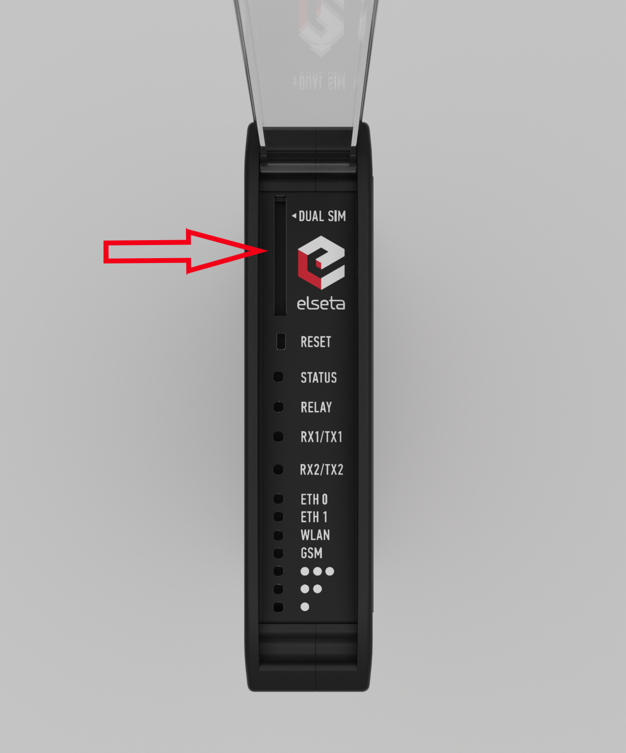](https://wiki.elseta.com/uploads/images/gallery/2022-11/image-1669194010051.png) Figure 5: WCC Lite Dual-SIM card slot # 5.4 Dual-SIM card slot WCC Lite has an optional dual-SIM card modem. To access both SIM cards, remove a transparent front panel cover and press through the marked hole with a small tool until the SIM holder pops out. [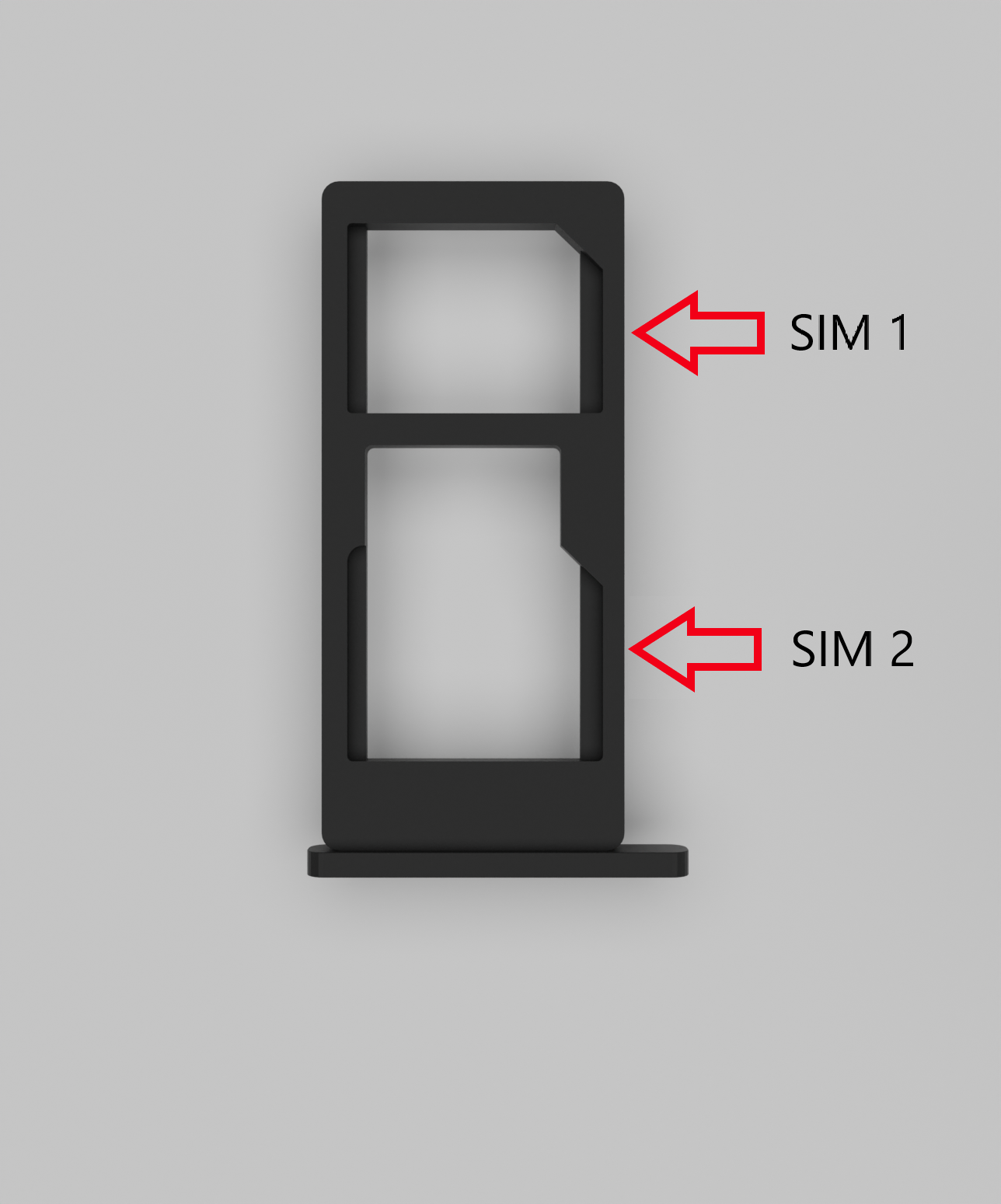](https://wiki.elseta.com/uploads/images/gallery/2022-11/image-1669194054543.png) Figure 6: WCC Lite Dual-SIM card holder To insert SIM cards, remove the Dual-SIM holder and fit SIM cards into it. Insert the holder with SIM cards into the slot.Note: Be careful when removing or inserting a DUAL-SIM holder, as SIM cards can fall out.
Note: WCC Lite will automatically detect a SIM card insertion or removal.
# 6 Interfaces WCC lite supports various interfaces to acquire data and control external circuitry. That includes two serial port interfaces, relay output, digital input, and external cellular connection antenna. # 6.1 Serial port interfaces WCC Lite WCC Lite has 2 serial ports (Figure 7). Selectable RS485 (by default) or RS232 interface on PORT1 and RS485 interface on PORT2. [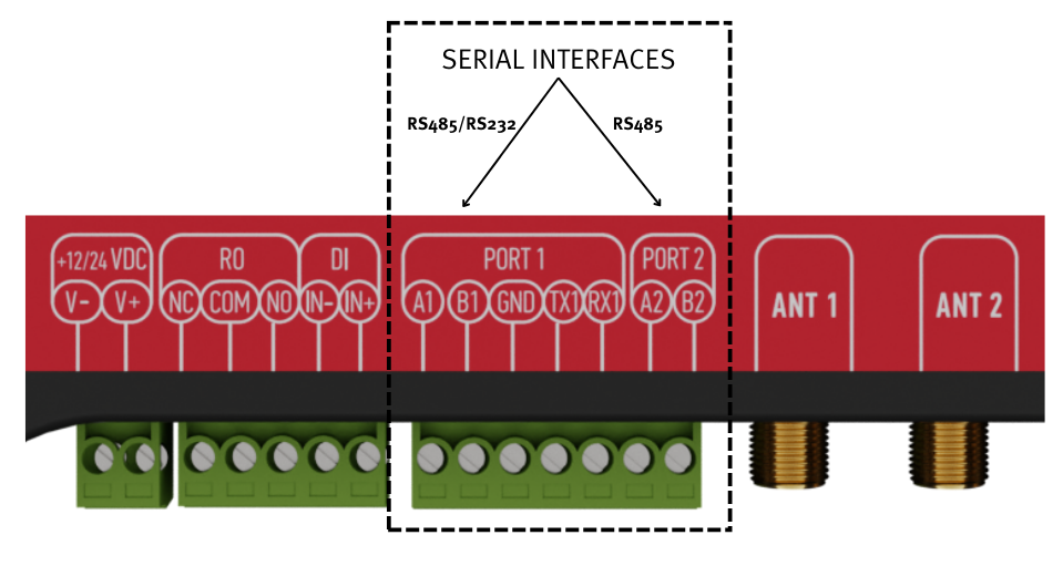](https://wiki.elseta.com/uploads/images/gallery/2022-11/image-1669194105015.png) Figure 7: WCC Lite ports WCC Lite RS485 interface supports baud rates up to 115200 and has an integrated 120 termination resistor. It is recommended to use termination at each end of the RS485 cable. To reduce reflections, keep the stubs (cable distance from the main RS485 bus line) as short as possible when connecting the device. See the typical RS485 connection diagram in Figure 8.Note: Double-check if the A and B wires are not mixed up.
WCC Lite 3-wire RS232 interface is available on PORT1 and can be selected by the user (see Port settings). Baud rates up to 115200 are supported. See the typical RS232 connection diagram in Figure 9. [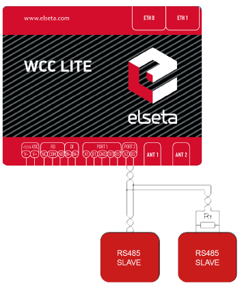](https://wiki.elseta.com/uploads/images/gallery/2022-03/image-1647614290547.png) Figure 8: Typical WCC Lite RS-485 connection diagram [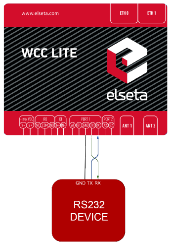](https://wiki.elseta.com/uploads/images/gallery/2022-03/image-1647614310588.png) Figure 9: Typical WCC Lite RS-232 connection diagram # 6.2 Relay output WCC Lite integrates 1 signal relay (3-way RO connector) with COM (common), NC (normally closed), and NO (normally open) signals. [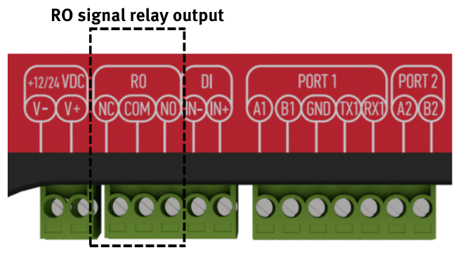](https://wiki.elseta.com/uploads/images/gallery/2022-11/image-1669194156568.png) Figure 10: Signal relay connector Maximum switching power is 60W, maximum contact current is 2A, maximum switching voltage is 60VDC/60VAC. The lower is switching power, the higher the lifecycle of Relay Output. Relay electrical endurance: - resistive load, 30VDC / 1A - 30W min. 1x10⁵ operations; - resistive load, 30VDC / 2A - 60W min. 1x10⁴ operations. # 6.3 Digital Input With WCC Lite hardware version 1.4, a digital input functionality has been introduced. Software configuration guidelines are discussed in the [WCC Lite internal signals section.](https://wiki.elseta.com/books/manual/page/19-wcc-lite-internal-signals) It changes state when the voltage is between 12-48V (The supported range is between 10-60V).| Input voltage | 12-48 VDC (accepts 10-60V) |
| Protection | ±60 VDC reverse polarity protection Isolated from the main logic |
4G (LTE) Cat 1 version modem both antennas are used for LTE communication. In such cases, an internal WIFI antenna is used. The network can be limited in distance and speed, especially in metal-based panels.
Make sure the signal level is over -80dBm to have a stable connection to the network. # 6.5 Wi-Fi For hardware versions older than version **1.4**, in case a Wi-Fi connection is needed, connect a Wi-fi antenna to the SMA connector labelled “WIFI“. Select a good antenna placement spot considering the operation environment. [](https://wiki.elseta.com/uploads/images/gallery/2023-08/image-1693316807761.png)Figure 1. Wi-Fi antenna connector (hardware version older than **1.4**) Newer hardware versions don’t have an option of connecting an external Wi-Fi antenna as MIMO capability for cellular modems has been introduced. In case stronger reach is needed, a user should contact the manufacturer to provide possible solutions. [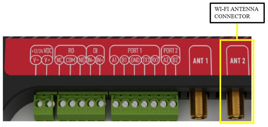](https://wiki.elseta.com/uploads/images/gallery/2023-09/image-1694092887560.png)Figure 2. Wi-Fi antenna connector (hardware version newer than **1.3**)Given that the default hardware configurations are set for GSM on connectors **ANT 1** and **ANT 2**, the Wi-Fi antenna shall remain non-operational in versions exceeding **1.3**. Users are advised to contact the manufacturer before purchasing the product if Wi-Fi functionality is required.
Make sure the signal level is over -80dBm to have a stable connection to the network.
# 7 Tags #### Single point Commonly used in storing digital states single point values have only one bit of information. The value of such tags can be either one or zero. On the internal web of WCC Lite states of this type of tags are shown in colored boxes with customisable labels.| Value | Representation |
| 0 | OFF |
| 1 | ON |
| Value | Representation |
| 00 | INDETERMINATE |
| 01 | OFF |
| 10 | ON |
| 11 | ERROR |
It is recommended to change the password immediately to avoid any unauthorized access.
Before plugging WCC Lite with a static IP address into the local computer network, make sure to check if such an address is not already reserved by other devices.
# 8.2 Site layout [](https://wiki.elseta.com/uploads/images/gallery/2021-11/image-1637918414929.png) It provides the main navigation through the website. Contains the following sections: - *PROTOCOL HUB*: configuration related to data exchange between WCC Lite and other devices. - *STATUS:* system information and diagnostics. - SYSTEM*:* basic system settings such as time setup. - *SERVICES:* various other services. - *NETWORK:* network-related settings and services. - *USERS*: existing user groups and management of their permissions - *LOGOUT:* user logout. # 8.3 Protocol Hub The Protocol HUB section stores the configuration for every connected device. You can configure it by importing settings from an Excel file.Avoid editing Excel configuration files via Google Docs or pasting values from unknown sources (especially websites or PDFs). That's because it may cause some errors related to formating of data.
#### Configuration [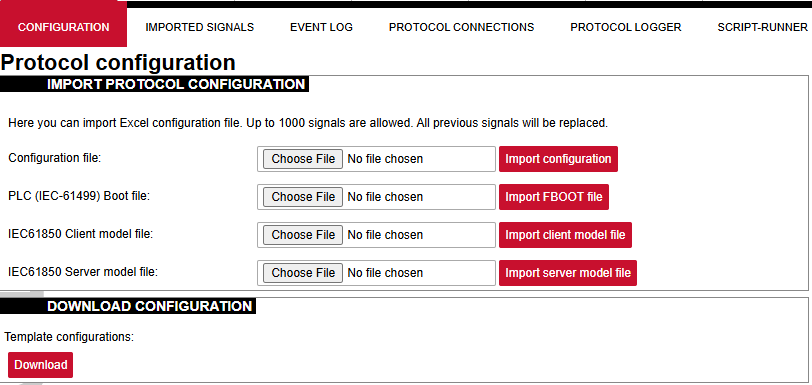](https://wiki.elseta.com/uploads/images/gallery/2024-12/image-1734013419648.png) In this tab, a user can: - Import new configuration from Excel file (.xls, .xlsx formats). If any errors in the file are found, the device will not be imported, and the importing process will be stopped. - Import .fboot file for PLC. - Import the IEC61850 Server model file - Import the IEC61850 Client model file - Download the current configuration Excel file. - Download a template configuration Excel file. #### Imported Signals [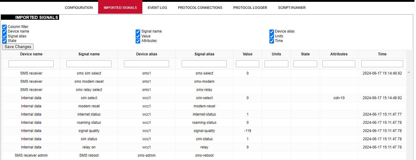](https://wiki.elseta.com/uploads/images/gallery/2024-12/image-1734013824379.png) The imported signals section shows basic information about the applied configuration. This section is used for viewing only. Column filter allows the signals to be filtered according to the information needed. #### Event Log [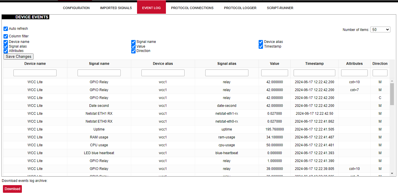](https://wiki.elseta.com/uploads/images/gallery/2024-12/image-1734014143755.png) Event Log is the timestamped status data. It allows reviewing the latest events and changes for devices' state changes in chronological order. The newest events are shown at the top of the list. WCC Lite will timestamp the status data with a time resolution of one millisecond. Column filter allows filtering of the data according to the information needed. Initially, all breakers, protection contacts digital status input points in the WCCLite; events captured from IEDs (Intelligent electronic devices) shall be configured as Event Log points. It’s possible to assign any digital status input data point in the WCCLite as an SOE point with an Excel template during configuration. Each time a device changes state, the WCClite will save it with timetag in internal storage. Event Log can also be downloaded by pressing the download button at the bottom of the page.Events are recorded only for devices with the *log* field set to 1.
#### Protocol Connections [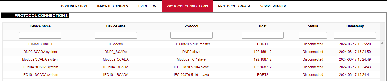](https://wiki.elseta.com/uploads/images/gallery/2024-12/image-1734014596119.png) The protocol connections section shows configured devices and their respective ports, and statuses. #### Protocol Logger [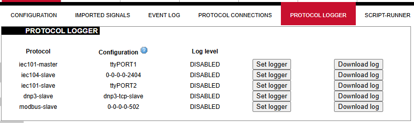](https://wiki.elseta.com/uploads/images/gallery/2024-12/image-1734015947140.png) Protocol logger allows users to set a certain debug level for any protocol. The debug log can then be downloaded as a file by clicking the Download log button. To set the logger, click on the Set logger button and select the debug level and time in which the logger will be active. Debug levels can be seen in the picture below. [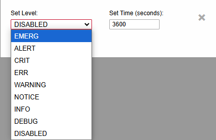](https://wiki.elseta.com/uploads/images/gallery/2024-12/image-1734076080857.png) # 8.4 Status ### Overview #### System [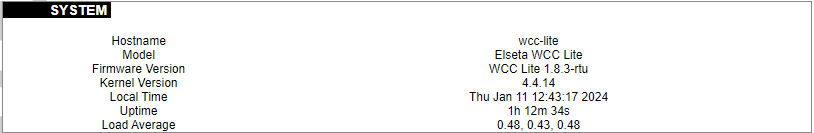](https://wiki.elseta.com/uploads/images/gallery/2024-01/image-1704969826976.png) The system section in the status tab shows basic information about the system's current status. Hostname: The label that is used to identify the device in the network. Model: Model of the device. Firmware version: Current firmware version. Kernel version: Current kernel version. Local Time: Current local time. Uptime: The time a device has been working. Load average: Measure CPU utilization of the last 1, 5, and 15-minute periods. A load of 0.5 means the CPU has been utilized 50% over the previous period. Values over 1.0 mean the system was overloaded. #### Memory [](https://wiki.elseta.com/uploads/images/gallery/2020-10/image-1601551636726.png) The ”Memory” window provides information on memory usage on the device. Total available memory: The amount of available memory that could be used over installed physical memory. Free: The amount of physical memory that is not currently used over installed physical memory. Buffered: The amount of buffered memory currently used for active I/O operations over installed physical memory. #### Network [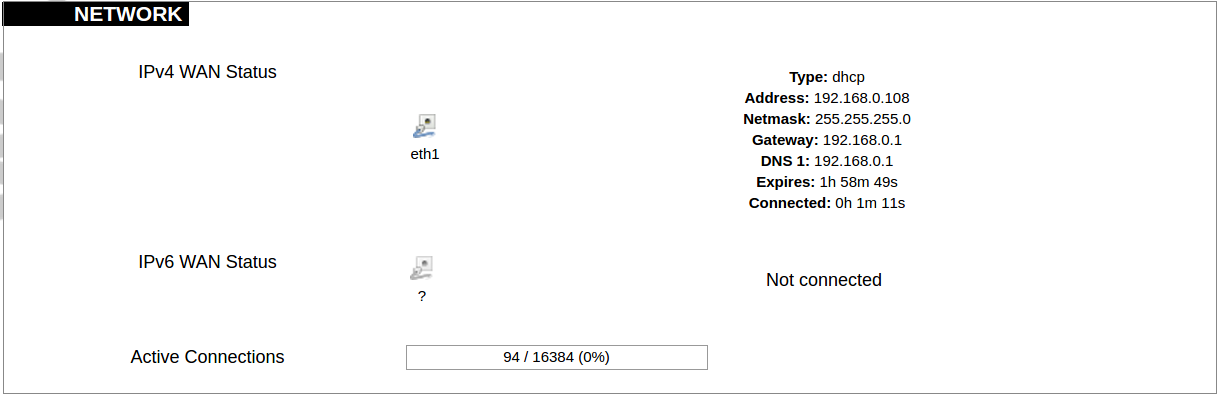](https://wiki.elseta.com/uploads/images/gallery/2020-10/image-1601551674236.png) IPv4 WAN, IPv6 WAN status, and active connections of the device. Type: Type of addressing of IPv4 network interface – DHCP or static. Address: IP address of the device. Netmask: Netmask of the device. Gateway: IP address of the Gateway. DNS: IP address of DNS server. Expires: DHCP lease expiration time of the connection. Connected: The time a device has been connected. Active Connections: The number of active connections with the device. #### Interfaces [](https://wiki.elseta.com/uploads/images/gallery/2024-08/image-1722943858982.png) Shows the IP of every active interface connection. #### DHCP leases [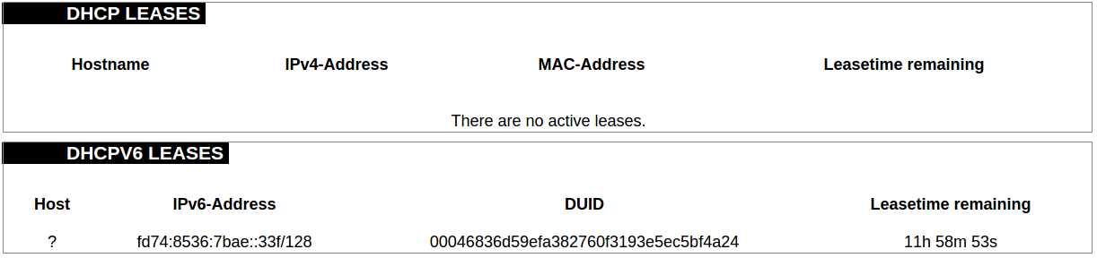](https://wiki.elseta.com/uploads/images/gallery/2020-10/image-1601551755263.png) DHCPv4 and DHCPv6 lease expiration time. Hostname: The label that is used to identify the device in the network. IPv4-Address: IPv4 address of network interface. MAC-Address: The media access control address of the IPv4 network interface. DUID: DHCP Unique Identifier of IPv6 network interface. Lease Time remaining: The amount of time the device will be allowed to connect to the Router. #### Wireless[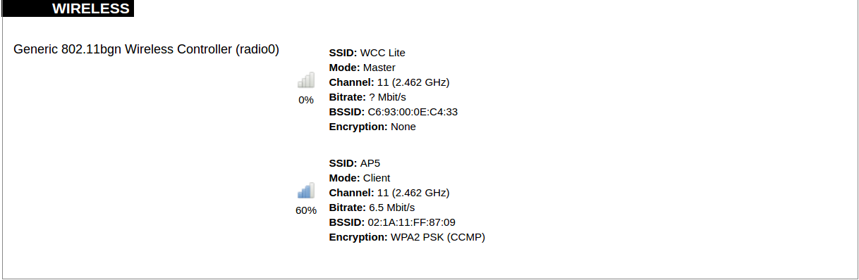](https://wiki.elseta.com/uploads/images/gallery/2020-10/image-1601551793225.png) WiFi interface information window. SSID: The sequence of characters that uniquely names a wireless local area network. Mode: Shows how the device is connected to the wireless network – Master or Client. Channel: The number of channels and radio frequency for connection to the access point. Bitrate: The number of bits that pass the device in a given amount of time. BSSID: The MAC address of the wireless access point. Encryption: Security protocol for the wireless network. #### Associated stations [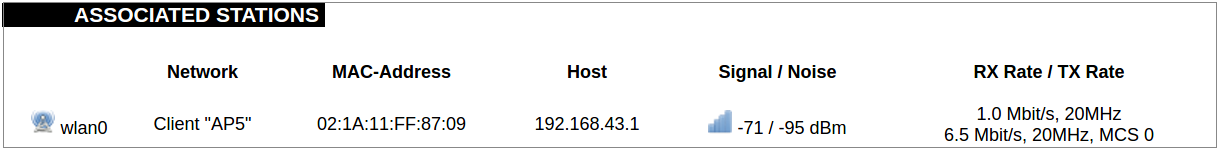](https://wiki.elseta.com/uploads/images/gallery/2020-10/image-1601551830832.png)List of associated stations (clients). Network: Mode and SSID of network point. MAC-Address: The media access control address of the IPv4 network interface. Hostname: The label or IP address that is used to identify the device in the network. Signal/Noise: Received signal level over the background noise level. -30 dBm is the maximum achievable signal strength, and -70 dBm is the minimum signal strength for reliable packet delivery in the wireless network. RX Rate/TX rate: Used to measure data transmission in the wireless network over bandwidth. RX Rate represents the rate at which data packets are received by the device, and the TX Rate represents the rate at which data packets are sent from the device. #### Board information [](https://wiki.elseta.com/uploads/images/gallery/2020-10/image-1601551883930.png)Board information provides the following details: Hardware version: Current hardware version; Serial number: Serial number of the board; SoC ID: Unique identifier of CPU unit; ### Firewall #### IPv4 Firewall [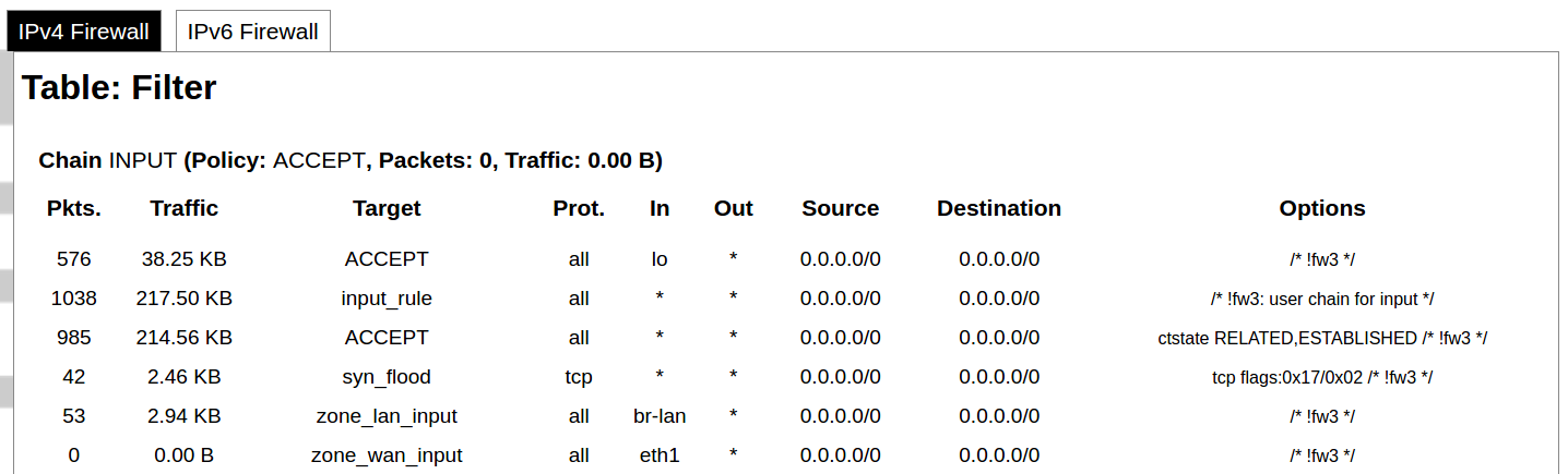](https://wiki.elseta.com/uploads/images/gallery/2020-10/image-1601552021522.png) Firewall rule list for IPv4 traffic. Table: The four distinct tables which store rules regulating operations on the packet. Filter concerns filtering rules. NAT concerns the translation of source or destination addresses and ports of packages. The mangle table is for specialized packet alteration. The raw table is for configuration exceptions. Chain: The list of rules. Filter table has the following built-in chains: Input – concerns packets whose destination is the firewall itself, Forward – concerns packets transiting through the firewall, Output – concerns packets emitted by the firewall, Reject – reject the packet, Accept – allow the packet to go on its way. NAT table has the following built-in chains: Prerouting – to modify packets as soon as they arrive, Postrouting – to modify packets when they are ready to go on their way. Mangle table has one built-in chain: Forward for transiting packets through the firewall. Pkts.: The packets are processed by the firewall. Traffic: The amount of data processed by the firewall. Target: The chain of the table of the firewall. Prot.: The transport layer protocol is processed by the firewall. In: The network interface for the input chain processed by the firewall. Out: The network interface for the output chain is processed by the firewall. Source: IPv4 address of the device that the packet comes from. Destination: IPv4 address of the device that the packet goes to. Options: The options for configuring the firewall. #### IPv6 Firewall [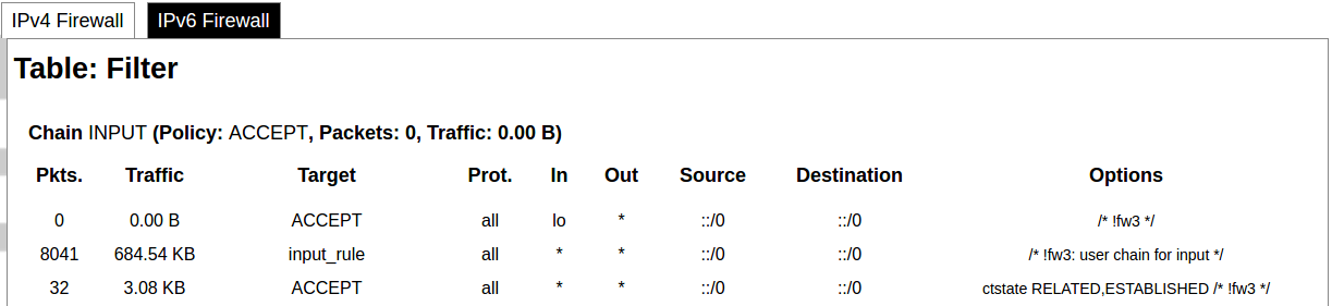](https://wiki.elseta.com/uploads/images/gallery/2020-10/image-1601552266384.png) Firewall rule list for IPv6 traffic. Table: The three distinct tables which store rules regulating operations on the packet. Filter concerns filtering rules. The mangle table is for specialized packet alteration. The raw table is for configuration exceptions. Chain: The list of rules. Filter table has the following built-in chains: Input – concerns packets whose destination is the firewall itself, Forward – concerns packets transiting through the firewall, Output – concerns packets emitted by the firewall, Reject – reject the packet, Accept – allow the packet to go on its way. Mangle table has one built-in chain: Forward for transiting packets through the firewall. Pkts.: The packets are processed by the firewall. Traffic: The amount of data processed by the firewall. Target: The chain of the table of the firewall. Prot.: The transport layer protocol is processed by the firewall. In: The network interface for the input chain processed by the firewall. Out: The network interface for the output chain is processed by the firewall. Source: IPv6 address of the device that the packet comes from. Destination: IPv6 address of the device that the packet goes to. Options: The options for configuring the firewall. ### Routes [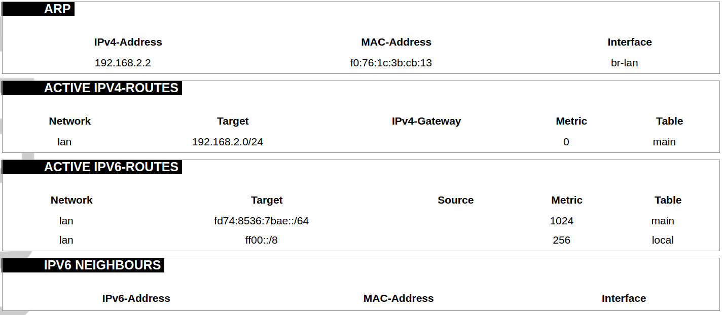](https://wiki.elseta.com/uploads/images/gallery/2020-10/image-1601552456174.png) The routing tables provide information on how datagrams are sent to their destinations. ARP: An address Resolution Protocol which defines how the IP address is converted to a physical hardware address needed to deliver packets to the devices. Interface: The type of Network interface. br-lan refers to the virtual bridged interface: to make multiple network interfaces act as if they were one network interface. Network: The type of network through which the traffic will be sent to the destination subnet. Target: An address of the destination network. The prefix /24 refers to the subnet mask 255.255.255.0. IPv4-Gateway: IP address of the gateway to which traffic intended for the destination subnet will be sent. Metric: The number of hops required to reach destinations via the gateway. Table: The type of routing tables: main (default), local (maintained by the kernel). IPv6 Neighbours: The devices on the same network with IPv6 addresses. ### System Log [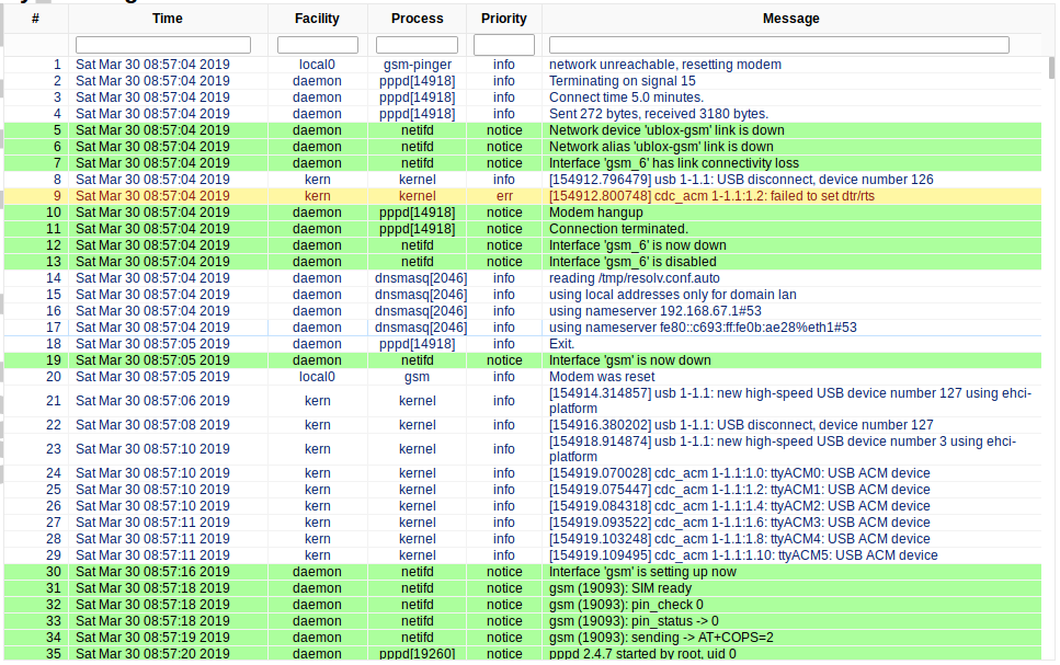](https://wiki.elseta.com/uploads/images/gallery/2020-10/image-1601552517322.png) The system log window shows a table containing the events that are logged by the device. It has the following columns: - \# (sequence number); - Time (day of the week, month, day of the month, time and year); - facility; - process (who generated the message); - priority level; - message. Messages can be sorted and filtered to extract a particular set of messages. This might be useful when debugging kernel or protocol-level problems. ### Kernel Log [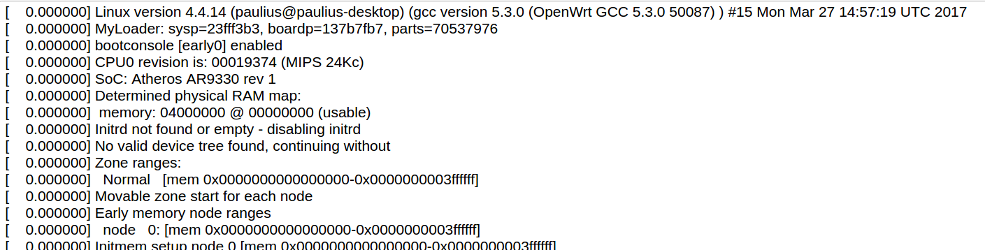](https://wiki.elseta.com/uploads/images/gallery/2020-10/image-1601552562425.png) The kernel log shows a list of the events that are logged by the kernel of the device. Log format: time in seconds since the kernel started and message. ### Chronos [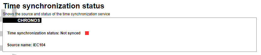](https://wiki.elseta.com/uploads/images/gallery/2024-08/image-1722944541181.png) Shows the source and status of the time synchronization service. ### Processes [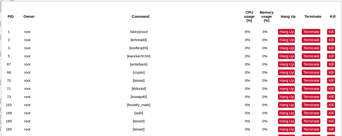](https://wiki.elseta.com/uploads/images/gallery/2020-10/image-1601552597976.png) List of processes running on the system. PID: Process ID. Owner: User to whom the process belongs. Command: Process. CPU usage: It is the CPU usage of the individual process. CPU usage above 90 % is an indicator of insufficient processing power. Memory usage: Memory usage of the individual process. Hang Up: To freeze the process. Terminate: To end the process cleanly. Kill: To end the process immediately. ### Realtime graph #### Realtime Load [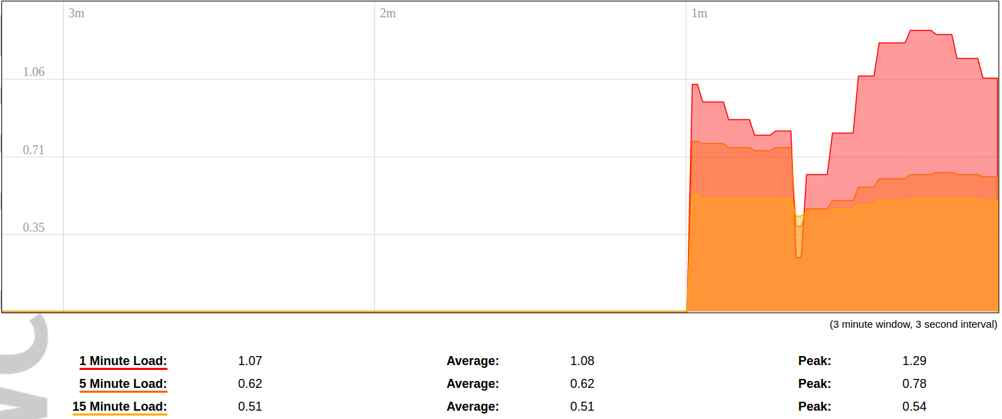](https://wiki.elseta.com/uploads/images/gallery/2020-10/image-1601552704789.png) CPU utilization graph. A load of 0.5 means the CPU has been 50% utilized over the last period. Values over 1.0 mean the system was overloaded. #### Realtime Traffic [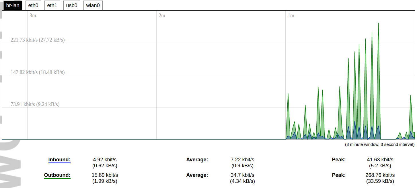](https://wiki.elseta.com/uploads/images/gallery/2020-10/image-1601552745346.png) Graphs representing the status of the virtual and physical network interfaces of the device. Inbound: The speed at which the incoming packets arrive at the device. Outbound: The speed of the packets which were originated by the device. Phy. Rate: The speed at which bits can be transmitted over the physical layer. #### Realtime Wireless [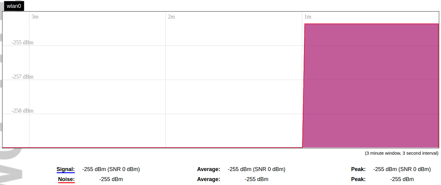](https://wiki.elseta.com/uploads/images/gallery/2020-10/image-1601552775159.png) WiFi status graph. Signal: Signal strength level. Noise: Noise level. Phy. Rate: The speed at which bits can be transmitted on the physical layer. #### Active connections [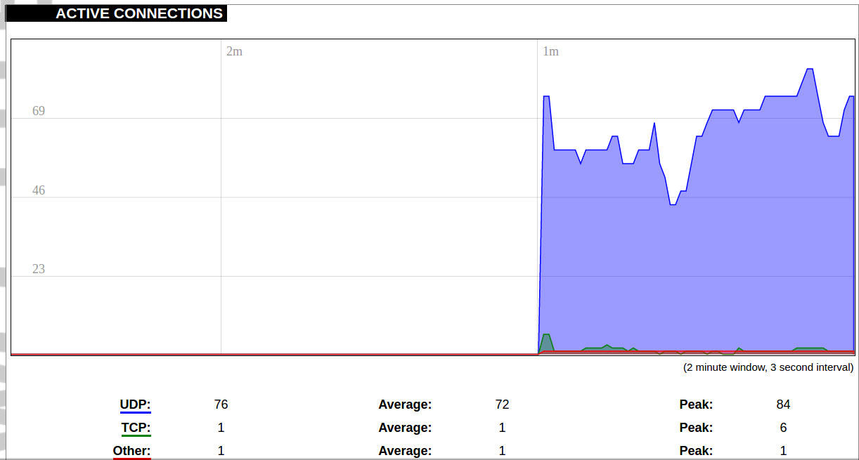](https://wiki.elseta.com/uploads/images/gallery/2020-10/image-1601552803957.png) Graph representation of active connections with the device. UDP: Transport layer – User Datagram Protocol. TCP: Transport layer – Transmission Control Protocol. Network: Type of the network layer – IPv4 or IPv6. Source, Destination: IP address and the port number. Transfer: The amount of the transferred data in kB and packets. #### Realtime GSM Signal Quality [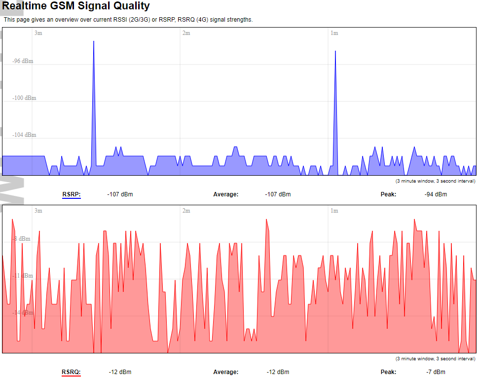](https://wiki.elseta.com/uploads/images/gallery/2024-08/image-1724396325411.png) Graph representation of gsm modem receiving signal quality. RSRP - RSRQ graph is shown, when connected to 4G/LTE network, RSSI - when 2G/3G networks are used. RSSI: Received Signal Strength Indicator in dBm. RSRP: Received Signal Reference Power in dBm.Signal quality is described in different ways for different types of mobile services: Received Signal Strength Indication (RSSI) in GSM (2G) and UMTS (3G), the Reference Signal Received Quality (RSRQ) in LTE RAT.
The Reference Signal Received Power (RSRP) is an LTE-specific measure that averages the power received by the subcarriers carrying the reference signal. The RSRP measurement bandwidth is equivalent to a single LTE subcarrier: its value is therefore much lower than the total received power usually referred to as RSSI. In LTE the RSSI depends on the currently allocated bandwidth, which is not pre-determined. Therefore the RSSI is not useful to describe the signal level in the cell.
### VNSTAT Traffic monitor To monitor the traffic of various network interfaces VNSTAT Traffic monitor can be used. Traffic tracking can be useful if the user wants to have precise information on how much data is used because it can have a dependency on data transmission costs, for example, mobile (cellular) data. #### Graph [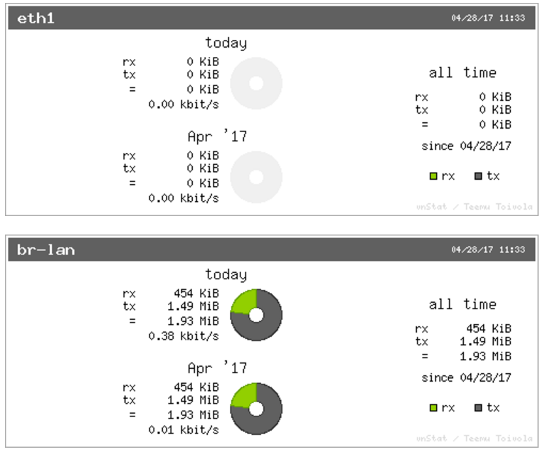](https://wiki.elseta.com/uploads/images/gallery/2020-10/image-1601554562243.png) An example graph shows the statistics gathered for two network interfaces. In these graphs: eth1: Network interface (e.g. Ethernet). br-lan: Virtual network interface (bridge). rx: Data packets received by the device. tx: Data packets sent from the device. #### Configuration [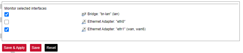](https://wiki.elseta.com/uploads/images/gallery/2023-07/image-1689081624381.png) Interfaces to be monitored can be selected in a configuration screen. It includes all the network interfaces configured in a system. To start or stop monitoring user should either select or unselect the respective checkbox and save settings by pressing Save & Apply. # 8.5 System ### System The system tab includes various properties, configurations, and settings of the system and contains the following pages: [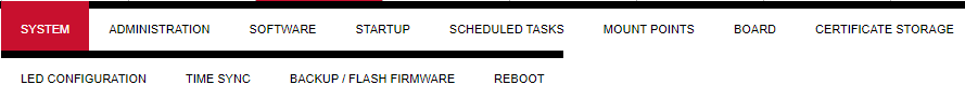](https://wiki.elseta.com/uploads/images/gallery/2023-07/image-1689082353519.png) • SYSTEM: properties and settings of the system. • ADMINISTRATION: settings of the administration for various services. • SOFTWARE: settings of the packages. • STARTUP: process management. • SCHEDULED TASKS: settings of the scheduled tasks. • MOUNT POINTS: settings for the mount points. • BOARD: board configuration. • CERTIFICATE STORAGE: certificate management panel. • LED CONFIGURATION: settings for the LEDs. • TIME SYNC: time synchronization of WCC Lite • BACKUP/FLASH FIRMWARE: management of the configuration files and firmware image upgrade. • REBOOT: device reboot page. #### System Basic aspects of the device can be configured. These include time settings, hostname, system event logging settings, language and theme selection. ##### **System Properties** ##### General Settings [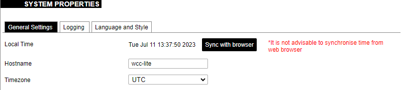](https://wiki.elseta.com/uploads/images/gallery/2023-07/image-1689082863834.png) The general settings of the WCC Lite device are defined as follows: Local Time: Current local time. Hostname: The label that is used to identify the device in the network. Timezone: A region of the globe that observes a uniform standard time. The time zone number indicates the number of hours by which the time is shifted ahead of or behind UTC – Coordinated Universal Time. Some zones are, however, shifted by 30 or 45 minutes. ##### Logging [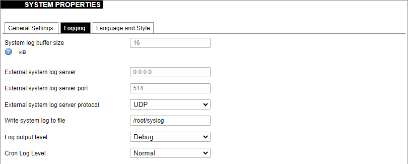](https://wiki.elseta.com/uploads/images/gallery/2023-07/image-1689082988260.png) Logging settings of the WCC Lite device are defined as follows: System log buffer size: The number of records that are recorded before writing these data to the disk. External system log server: IP address of the server. External system log server port: An endpoint of communication with the server. External system log server protocol: A standard that defines how to establish and maintain a network connection: UDP - User Datagram Protocol, TCP - Transmission Control Protocol. Write system log to file: The name of the file with the path to it. Log output level: Log output messages can be grouped by their importance to the user. Levels are described in the table below.| **Log output level** | **Description** |
| Emergency | System is unusable |
| Alert | Action must be taken immediately |
| Critical | Critical conditions |
| Error | Error conditions |
| Warning | Potentially hazardous conditions |
| Notice | Normal conditions that might need action |
| Info | Information messages |
| Debug | Debugging messages |
| **Cron log level** | **Description** |
| Debug | Debugging messages |
| Normal | General administrative messages |
| Warning | Potentially hazardous conditions |
It is advised not to use the default password.
##### Password policy [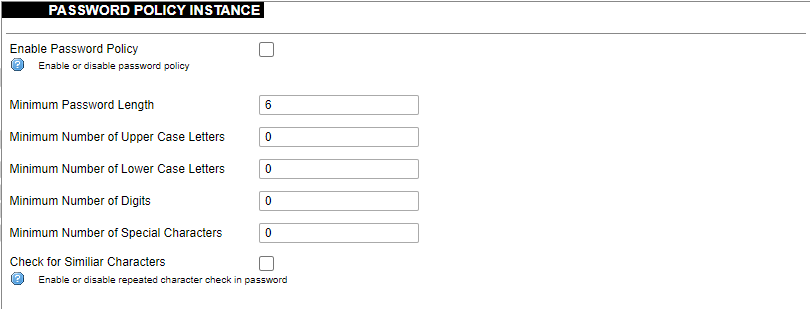](https://wiki.elseta.com/uploads/images/gallery/2023-07/image-1689083560180.png) Users can configure a password policy for future password changes to create a safer password. Here password requirements can be made such as minimum password length, minimum number of upper or lower case letters, digits and special characters. By ticking the box for checking similar characters, a new password will be required not to have repeated characters. ##### SSH Access WCC Lite has a compact secure shell (SSH) server named Dropbear. Multiple options are available to be changed via the WCC Lite web interface, ranging from automatic firewall rules to authentication flexibility. [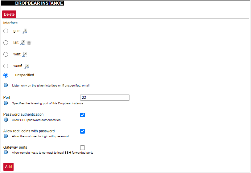](https://wiki.elseta.com/uploads/images/gallery/2023-07/image-1689157365613.png) Dropbear options are defined as follows: Interface: Listen only on the given interface or on all, in unspecified. Port: Specifies the listening port of this interface. Password authentication: Allow SSH password authentication. Allow root logins with password: Allow the root user to log in with the password. Gateway ports: Allow remote hosts to connect to local SSH forwarded ports. #### SSH-keys [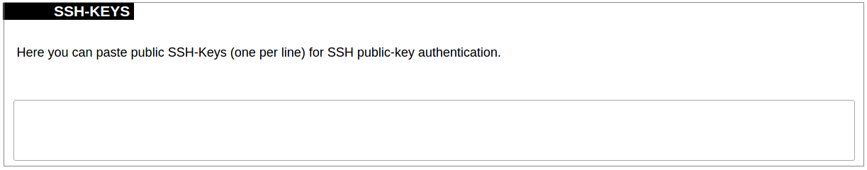](https://wiki.elseta.com/uploads/images/gallery/2020-10/image-1601560050675.png) SSH keys can be added via the WCC Lite web interface. They might be helpful if the user logs into the device frequently and does not want to always have to write his credentials. ##### Login Attempt limiterThis feature is available from firmware version 1.9.1
[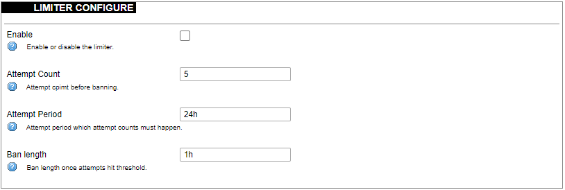](https://wiki.elseta.com/uploads/images/gallery/2024-08/image-1723018327646.png) Enforce a limit of invalid access attempts and deny access from a virtual port for a set time. ##### RADIUS Client [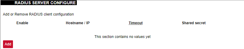](https://wiki.elseta.com/uploads/images/gallery/2023-07/image-1689157681368.png) RADIUS client redirects user authorization to a remote server, which controls users and their access. A user can add multiple RADIUS clients by clicking add and entering the information required. ##### HTTPS certificate [](https://wiki.elseta.com/uploads/images/gallery/2020-10/image-1601560081935.png) WCC Lite by default is shipped with a default certificate for HTTPS connection. This certificate only enables connecting to the device via a web interface and might cause warnings from a web browser. To eliminate them, the user can use his certificate to secure access to the web interface. Users can use certificates uploaded to a certificate storage. It should be noted that only valid certificates with \*.pem extension can be used. The certificate to be used is validated every time the device is restarted. If validation fails, a default certificate is used. This is done to prevent users from losing device access via the web interface. For the new certificate to come into effect user should restart the device. ### Software Individual packages can be installed via the WCC Lite web interface. They can either be installed using a web link or selected from the pre-defined feeds. [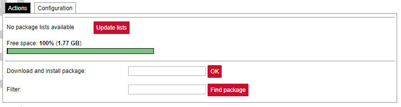](https://wiki.elseta.com/uploads/images/gallery/2024-08/image-1723100604294.png) Various options can be selected when installing packages, however, default ones should work well enough and it’s advised only to change them for advanced users. [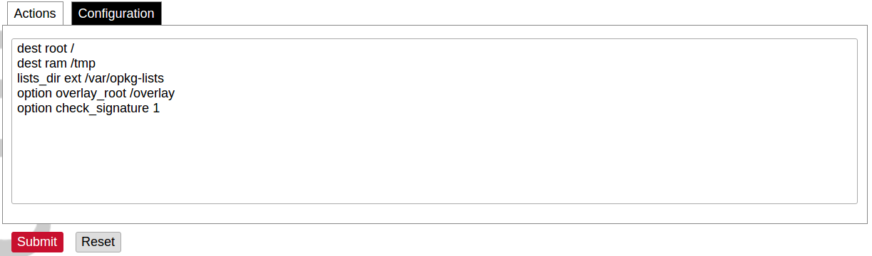](https://wiki.elseta.com/uploads/images/gallery/2020-10/image-1601560339950.png) Feeds from which packages are listed for the update are defined in the Open PacKaGe management (OPKG) configuration that can be changed easily from the user interface. [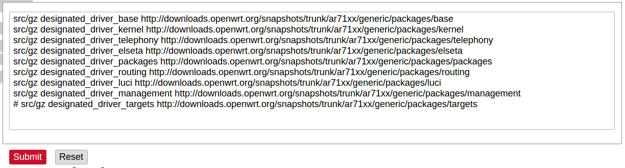](https://wiki.elseta.com/uploads/images/gallery/2020-10/image-1601560359726.png) Specific distribution feeds can also be added for special cases if standard ones do not fit the needs. [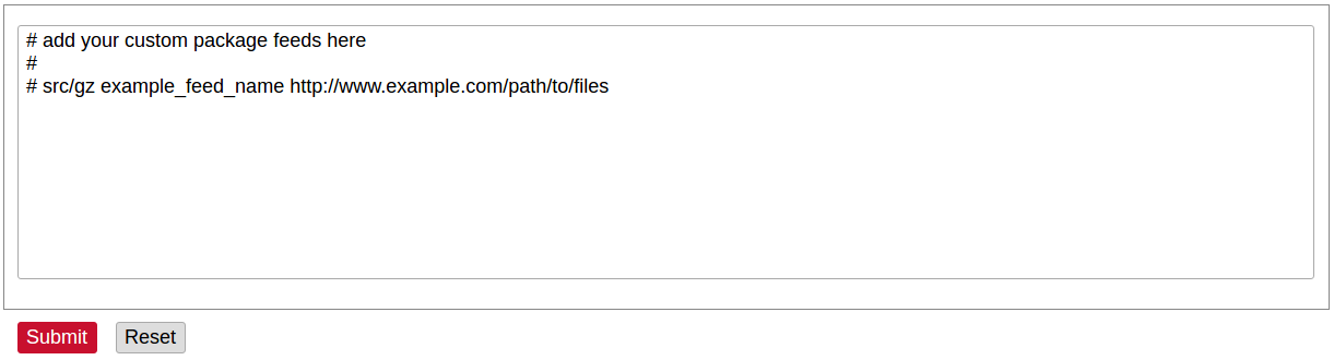](https://wiki.elseta.com/uploads/images/gallery/2020-10/image-1601560377187.png) [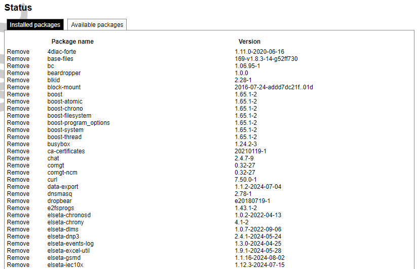](https://wiki.elseta.com/uploads/images/gallery/2024-08/image-1723103500206.png) The installed packages tab indicates every installed package in alphabetical order. Users can also remove certain packages by clicking the Remove button on the left. [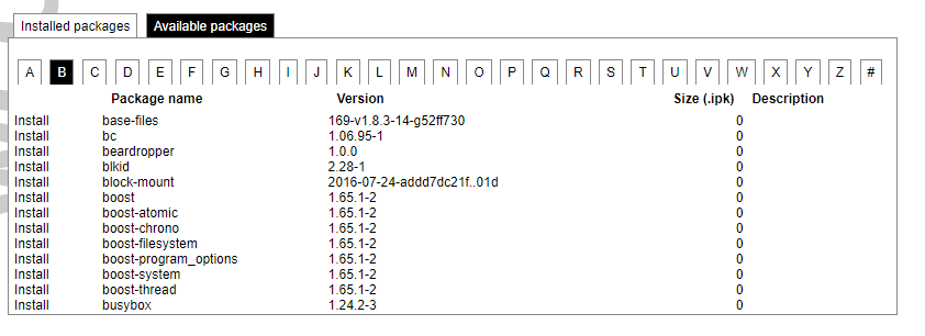](https://wiki.elseta.com/uploads/images/gallery/2024-08/image-1723103835627.png) In this tab, the user can search for a package by the first letter of its name. Those packages are available but not installed, so the user can choose to install them by clicking on the Install button on the left. ### Startup All of the processes that have init.d scripts can optionally be enabled or disabled. This can be very useful if the user intends to use only part of the processes. [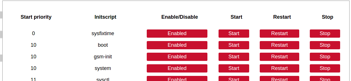](https://wiki.elseta.com/uploads/images/gallery/2020-10/image-1601560412520.png)Users should not disable processes that are essential for device operation as it can render the device unusable.
[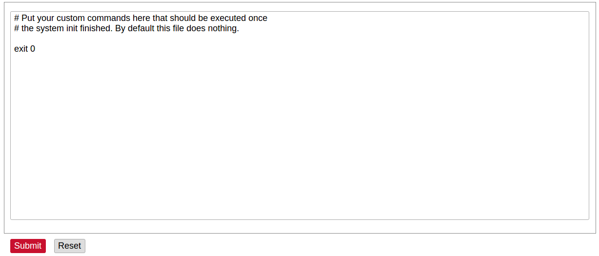](https://wiki.elseta.com/uploads/images/gallery/2020-10/image-1601560436943.png) Users can optionally run scripts and programs on device startup by putting them into a /etc/rc.local file. This file can be updated from the WCC Web interface. ### Scheduled tasks [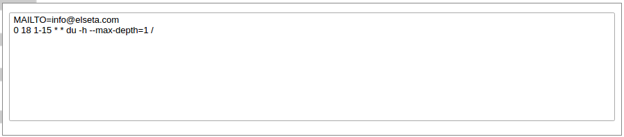](https://wiki.elseta.com/uploads/images/gallery/2020-10/image-1601560465567.png) Various tasks can be scheduled with the system crontab. New tasks can be included by creating and saving new rules conforming to cron rules. WCC Lite accepts full cron configuration functionality. The example in the pictures shows how to execute the disk usage command to get the directory sizes every 6 p.m. on the 1st through the 15th of each month. E-mail is sent to the specified email address. ### Mount points #### Global settings [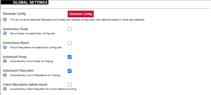](https://wiki.elseta.com/uploads/images/gallery/2023-07/image-1689158646715.png) File system mount point configuration window. Generate Config: Find all currently attached filesystems and swap and replace configuration with defaults based on what was detected. Anonymous Swap: Mount swap not specifically configured. Anonymous Mount: Mount filesystems not specifically configured. Automount Swap: Automatically mount swap on hotplug. Automount Filesystem: Automatically mount filesystems on hotplug. Check filesystems before mount: Automatically check the filesystem for errors before mounting. #### Mounted file systems [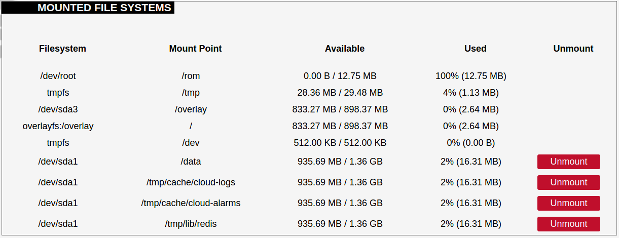](https://wiki.elseta.com/uploads/images/gallery/2020-10/image-1601560579298.png) List of mounted file systems, some of which can be dismounted manually. #### Mount points [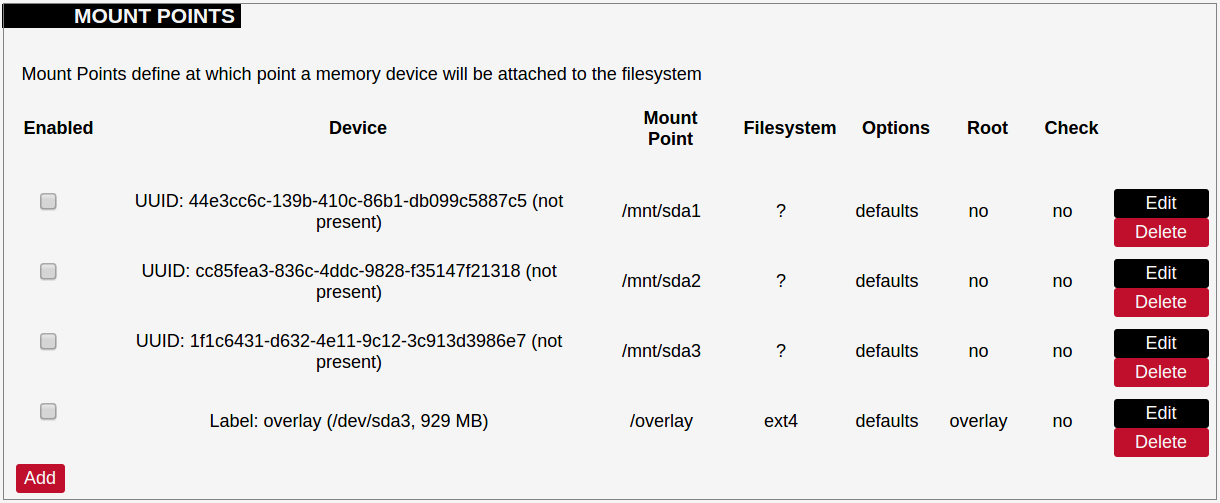](https://wiki.elseta.com/uploads/images/gallery/2020-10/image-1601560604355.png) List of mount points which can be enabled, disabled or deleted. #### Swap The swap section is used to describe the virtual memory that can be used if there’s a lack of main memory. WCC Lite does not use any virtual memory by default. [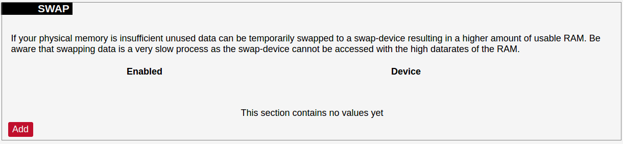](https://wiki.elseta.com/uploads/images/gallery/2020-10/image-1601560651205.png)It should be noted that virtual memory might do a lot of reading and writing operations. As WCC Lite uses an SD card as an additional flash memory, it is highly advised to not use a swap to reduce wearing.
### Board [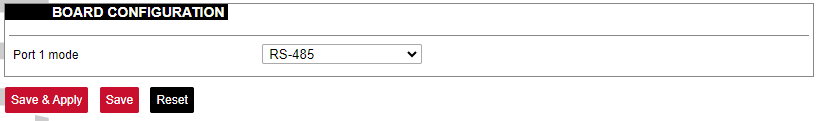](https://wiki.elseta.com/uploads/images/gallery/2023-07/image-1689158839403.png) Here a user can configure PORT1 as RS-485 or RS-232. ### Certificate storage [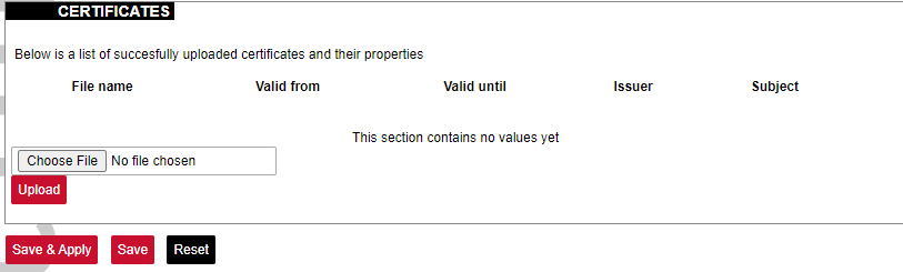](https://wiki.elseta.com/uploads/images/gallery/2023-07/image-1689159555059.png) This section is intended to upload certificate files and view information about them. ### LED configuration WCC Lite has three LEDs that can be configured: WAN, LAN and WLAN. All of the LEDs have a default configuration which should fit most of the cases. [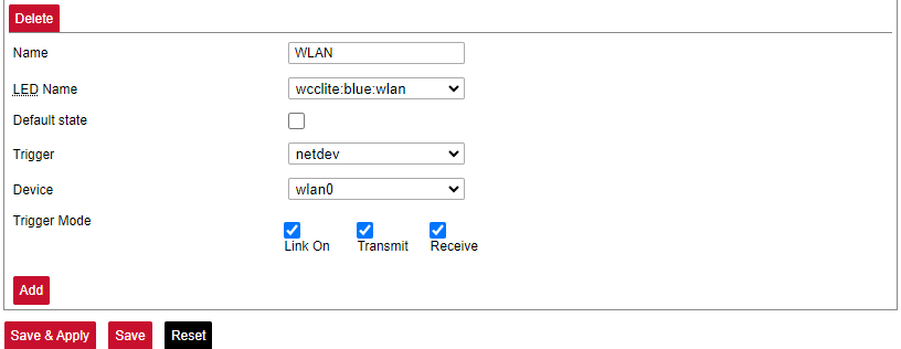](https://wiki.elseta.com/uploads/images/gallery/2023-07/image-1689159741014.png) All possible LED configuration options: Name: Name of the LED configuration. LED Name: Colour and location of the LED. These can be changed, however, normally they should be left unchanged. Default state of the LED: On/Off. Trigger: One of the various triggers can be assigned to an LED to change its state. Possible values are shown in the table below. Table. Possible trigger for an LED:| Trigger type | Description |
| none | No blinking function assigned to the LED |
| defaulton | LED always stays on |
| timer | Blinking according to a predefined timer pattern |
| heartbeat | Simulating actual heartbeats |
| nand-disk | Flashed as data is written to flash memory |
| netdev | Flashes according to link status and send/receive activity |
| phy0rx, phy0tx, phy0radio, phy0tpt, phy0assoc | Flashed on WiFi activity events |
| usbdev | Turned on when the USB device is connected. Applicable for modems |
Please take care choosing a time sync method. If both NTP and IEC 60870-5 protocol slave interface time sync methods are activated simultaneously, they can interfere if there is a time difference. We strongly recommend using a single-time sync method to prevent time interference.
Time synchronization options are defined as: Enable NTP client: The local time of the device will sync with external time servers. Provide NTP server: Turn the device into a local NTP server. NTP server candidates: The network time protocol servers. ### Backup/flash firmware Software update allows to upgrade of the software running in WCC Lite. It is recommended to keep the device up to date to receive the latest features and stability fixes. Backup archives contain complete WCC Lite configuration that can be restored at any time. A file will be downloaded by your browser when creating a backup. This file can be later uploaded to the web page to restore configuration.The generated backup archive should only be applied to the same firmware version it was generated. Applying backup to a different firmware version might render some parts of the operating system unstable or even unusable
[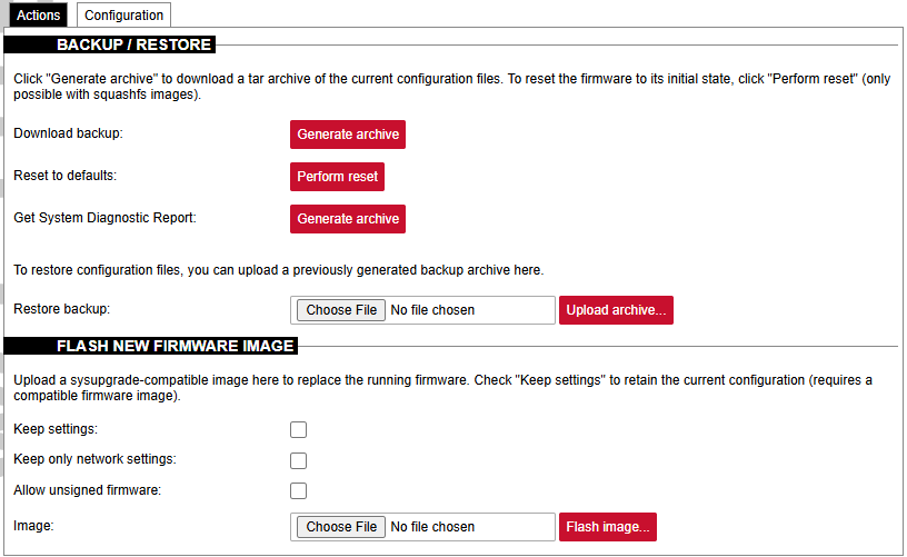](https://wiki.elseta.com/uploads/images/gallery/2024-12/image-1734076844325.png)Since version 1.8.3, users can save network settings before upgrading the firmware, such as firewall settings, traffic rules, interfaces etc. To do so, before upgrading firmware, the "Keep only network settings:" box should be checked.
Since version 1.10 all firmware files are signed and have different file extensions. If there is a need to downgrade a firmware version from 1.10, the *Allow unsigned firmware* box should be checked.
A user can choose to keep existing settings after an upgrade. Marking the Keep Settings checkbox preserves files listed in /etc/sysupgrade.conf and /lib/upgrade/keep.d/. It is advised to do a clean install and use backup files to restore settings later if a user intends to make a major system upgrade.Uploading firmware images, to preserve RAM, will stop all Protocol HUB processes. After upload, you will have 2 minutes to proceed with firmware flash or to cancel it. After 2 minutes, the firmware file will be deleted and Protocol HUB processes will be restarted.
[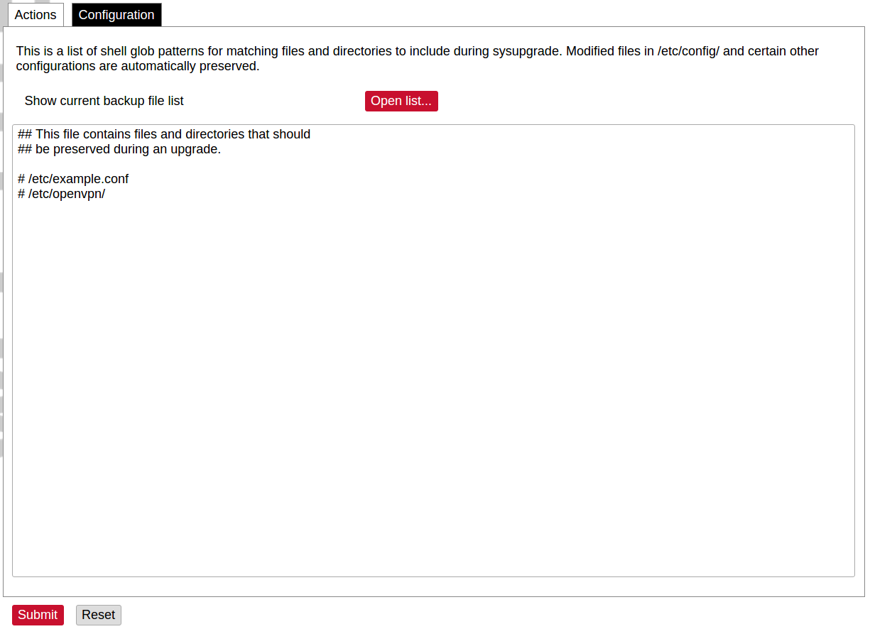](https://wiki.elseta.com/uploads/images/gallery/2020-10/image-1601561479820.png) A file name /etc/sysupgrade.conf can be updated via the WCC Web interface. To preserve additional files user should add them to the backup file and press Submit. To get the whole list of files that would be backed up press Open list... It is advised to check it before doing a backup or an upgrade while keeping settings. ### Reboot [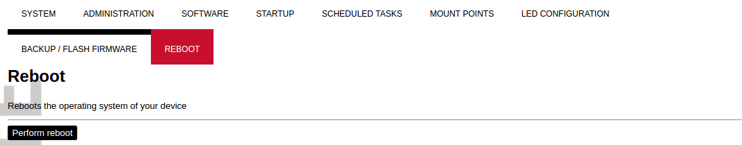](https://wiki.elseta.com/uploads/images/gallery/2020-10/image-1601561516242.png) This reboots the operating system of the device. # 8.6 Services The services tab shows the services of the device and contains the following subsections: [](https://wiki.elseta.com/uploads/images/gallery/2020-10/image-1601563935032.png) The services tab shows the services of the device and contains the following subsections: - TELEMETRY AGENT: device telemetry sent to a remote server; - IPSEC: encrypted virtual private network (VPN) configuration. - API: application programming interface configuration. - OPENVPN: shows the open-source software application that implements a virtual private network (VPN). - SER2NET: network-to-serial proxy; ### Telemetry agent Having data about the device helps to easily maintain it. Telemetry agent gathers information in a compact and easily decodable way. It uses UDP packets therefore only a small overhead is introduced. However, UDP does not guarantee the arrival of sent packets therefore not every message might reach the server saving these messages. To start using a Telemetry agent a user should configure and enable it. Four options are available: - Enable agent; - Server address; - Port (UDP); - Period (s). Every time the timer of period length expires, a message is sent to a server of the configured server if the service is enabled.The telemetry agent doesn’t start as a service if the Enable agent checkbox is unchecked.
Enabling the agent and saving the configuration automatically starts the process with the new configuration.
### IPsec #### Background WCC Lite supports ipsec VPN and thus can deliver data securely over encrypted links. To establish ipsec vpn, a connection definition must be created by entering the appropriate configuration settings. For advanced connection description auxiliary settings sets can be defined. They can be joined to the connection and can be reusable several times according to the need. Each configuration record is identified by a unique name, which is assigned at the time of creation. The following diagram shows the relations between connection and auxiliary sets. [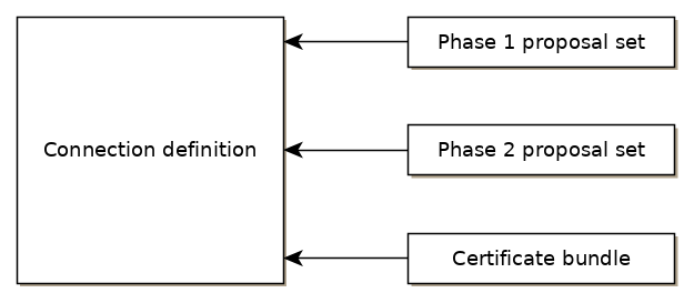](https://wiki.elseta.com/uploads/images/gallery/2020-10/image-1601564177757.png) #### Ipsec settings ##### Connection description Options supported by WCC lite are described below.| Item | Type | Description |
| Gateway | string | Host name or IP address of the remote peer. |
| Type | selector | Tunnel mode: full packet encryption, covers host-to-host, host-to-subnet, subnet-to-subnet situations or transport mode: ip payload encryption, secures host-to-host data only. |
| Local subnet | string | Specifies local network, in the form of network/netmask, for example 192.168.11.0/24 |
| Remote subnet | string | Specifies remote network at another side of a tunnel. |
| Authentication | selector | Pre-shared key or RSA certificate |
| Pre-shared key | string | Available if Authentication is set to Pre-shared key |
| Certificate set | selector | Available if Authentication is set to RSA certificate. Selectable from the configured auxiliary set. |
| Phase 1 proposal (IKE) | selector | Authentication-encryption schema, selectable from configured auxiliary set. |
| Phase 2 proposal (ESP) | selector | Authentication-encryption schema, selectable from configured auxiliary set. |
| Local ID | string | Specifies the identity of the local endpoint |
| Remote ID | string | Specifies the identity of the remote endpoint |
| Key exchange | selector | Sets method of key exchange IKEv2 or IKEv1. Default IKEv2. |
| Exchange mode | selector | Main or aggressive. Available if key exchange is set to IKEv1. |
| Use compression | checkbox | If selected a compression ability will be proposed to the peer. |
| DPD action | selector | Controls the use of dead peer detection protocol, values: - none – default, disables sending of DPD messages. - clear – the connection closed with no action. - hold – keeps description, tries re-negotiate connection on demand. - restart – will try to re-negotiate immediately. |
| DPD delay | string | Time interval in seconds between peer checks. Default 30. |
| DPD timeout | string | Time in seconds after which peers consider it to be unusable. IKEv1 only. Default 150. |
| Key lifetime | string | Lifetime of data channel in seconds. Default 10800. |
| IKE lifetime | string | Lifetime of keying channel in seconds. Default 3600. |
| Item | Type | Description | Note |
| Encryption algorithm | selector | Encryption algorithm – 3DES, AES128, AES192, AES256. | required |
| Hash algorithm | selector | Hash algorithm – MD5, SHA1, SHA256, SHA384 or SHA512. | required |
| DH exponentiation | selector | Specifies Diffie-Hellman groups – 1,2,5,14,15,16,18 | required |
| Item | Type | Description | Note |
| Encryption algorithm | selector | Encryption algorithm – 3DES, AES128, AES192, AES256. | required |
| Hash algorithm | selector | Hash algorithm – MD5, SHA1, SHA256, SHA384 or SHA512. | required |
| DH exponentiation | selector | Specifies Diffie-Hellman groups – 1,2,5,14,15,16,18 | optional |
The following specification and topology map correspond to settings used in further configuration walk-through examples.
#### Creating a connection description ##### Site-to-Site VPN scenario [](https://wiki.elseta.com/uploads/images/gallery/2020-10/image-1601565165686.png) ##### VPN connection details Tunnel: demoo ```demoo IPSec peer: ipsec.vpn.net Pre-shared key: thebigsecret Mode: tunnel Remote network: 10.10.10.10/24 Local network: 10.10.12.0/24 Local ID: wcclite IKE authentication: aes256 IKE hash: sha256 IKE DH group: 5 (modp1536) ESP authentication: aes128 ESP hash: sha1 ```If auxiliary data is needed, it is recommended to check or define it first.
##### Creation of Phase 1 proposal - Enter the section “Phase 1 proposals”. - Create a new record by assigning a new name, for example, “aes256-sha256-dh5” and click the button “Add”. - Choose corresponding values: encryption, hash algorithm and DH exponentiation. - Push “save” to save the data. [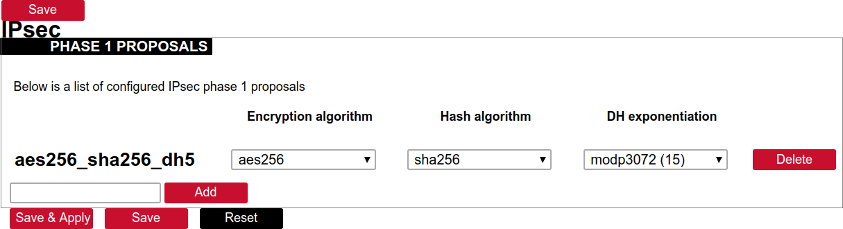](https://wiki.elseta.com/uploads/images/gallery/2020-10/image-1601568023894.png) ##### Creation of Phase 2 proposal - Enter the section “Phase 2 proposals”. - Create a new record by assigning a new name for example “aes128-sha1” and click the button “Add”. - Choose corresponding values: encryption, hash algorithm. - Push “save” to save the data. [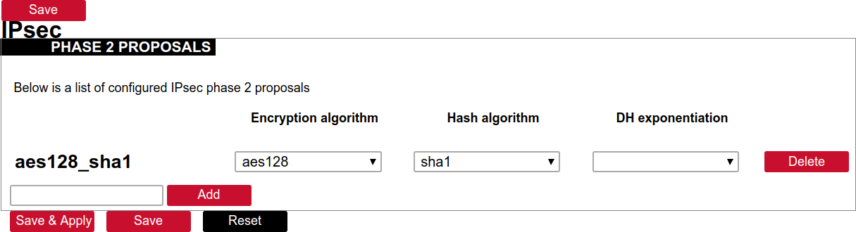](https://wiki.elseta.com/uploads/images/gallery/2020-10/image-1601568071003.png) ##### Creation of tunnel definition Enter section connections - Create a new record by assigning a new name (e.g.“demo0”) and clicking “Add”. - Call a detailed form by pushing the button “edit”. - Enter peer address into “Gateway”: “ipsec.vpn.net”. - Ensure “Type” is set to: “Tunnel”. - Fill local subnet to: 10.10.12.0/24. - Fill remote subnet to: 10.10.10.0/24. - Make sure authentication is set to: “Shared secret”. - Enter Pre-shared key (PSK): thebigsecret. - “Phase 1 proposal (IKE)”, choose a value: aes256\_sha256\_dh5. - “Phase 2 proposal (ESP)”, choose a value: aes128\_sha1. - Locate the combo box “additional field”, select “Local ID”, then set the value to wcclite. - Push “Save”. [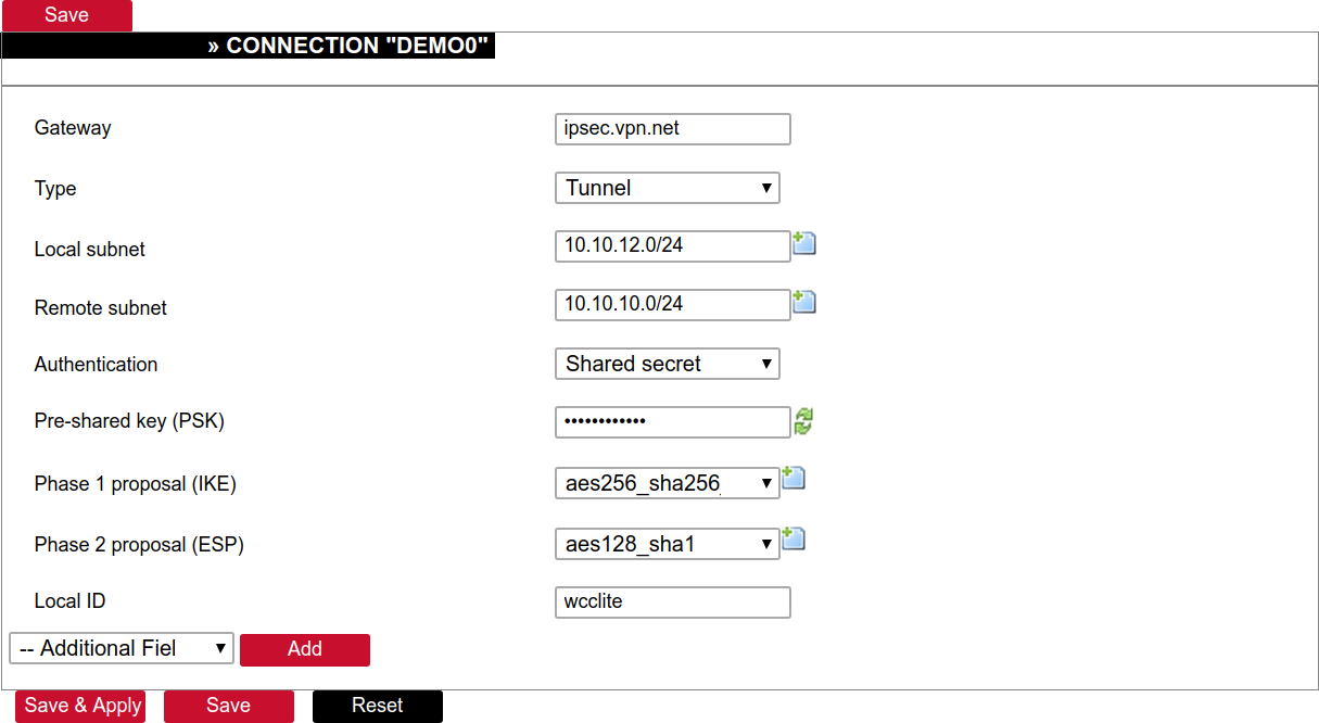](https://wiki.elseta.com/uploads/images/gallery/2020-10/image-1601568148856.png) ##### Activating the tunnel - Return to the section “connections”. - Check the checkbox “Enabled”. - Push the button “save & apply”. - Examine the indicator “configured”, it should be “yes”, if not, review the settings just entered. - The tunnel should be prepared for operation and will be established on demand. - Optionally, it is possible to establish tunnel operation by pressing the button “start”. [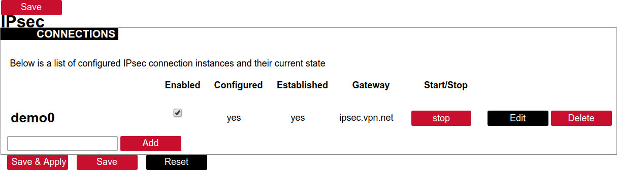](https://wiki.elseta.com/uploads/images/gallery/2020-10/image-1601568201450.png) ### L2TP/IPsec Because of the lack of confidentiality inherent in the L2TP protocol, it is often implemented along with IPsec. This is referred to as L2TP/IPsec and is standardized in IETF RFC 3193. The process of setting up an L2TP/IPsec VPN is as follows: - Negotiation of IPsec security association (SA), typically through Internet key exchange (IKE). This is carried out over UDP port 500, and commonly uses either a shared password (so-called ”pre-shared keys”), public keys, or X.509 certificates on both ends, although other keying methods exist. - Establishment of Encapsulating Security Payload (ESP) communication in transport mode. The IP protocol number for ESP is 50 (compare TCP’s 6 and UDP’s 17). At this point, a secure channel has been established, but no tunnelling is taking place. - Negotiation and establishment of an L2TP tunnel between the SA endpoints. The actual negotiation of parameters takes place over the SA’s secure channel, within the IPsec encryption. L2TP uses UDP port 1701. When the process is complete, L2TP packets between the endpoints are encapsulated by IPsec. Since the L2TP packet itself is wrapped and hidden within the IPsec packet, no information about the internal private network can be gathered from the encrypted packet. Also, it is not necessary to open UDP port 1701 on firewalls between the endpoints, since the inner packets are not acted upon until after IPsec data has been decrypted and stripped, which only takes place at the endpoints. A potential point of confusion in L2TP/IPsec is the use of the terms tunnel and secure channel. The term tunnel refers to a channel which allows untouched packets of one network to be transported over another network. In the case of L2TP/PPP, it allows L2TP/PPP packets to be transported over IP. A secure channel refers to a connection within which the confidentiality of all data is guaranteed. In L2TP/IPsec, first IPsec provides a secure channel, and then L2TP provides a tunnel. ### API The firmware of the WCC Lite features a built-in API which is accessible via the web interface.As of version 1.2.11, it does not implement any access restriction features apart from those provided by the firewall functionality.
Individual API endpoints can be enabled or disabled via the web configuration interface at Services->API.All endpoints are disabled by default.
Available API endpoints are shown in the table below. Table. Available API endpoints:| Endpoint | Description |
| /api/version | Version of the API |
| /api/actions | List of available points |
| /api/syncVersion | A version of the sync service |
| /api/sync | Protocol hub configuration sync (name=”file”)\* |
| /api/syslog | Prints out the syslog |
| /api/systemInfo | General system info |
| /api/gsmInfo | GSM modem information |
| /api/devices | List of configured devices |
| /api/device/info | Device information (name=”device\_alias”)\*\* |
| /api/device/tags | List of tags on a particular device (name=”device\_alias”)\*\* |
| /api/device/tag/value | Tag value (name=”device\_alias”, name=”signal\_alias”)\*\* |
| /api/tags | List of configured tags |
| /api/sysupgrade | Firmware upgrade (name=”file”)\* |
| eth0 | eth1 | |
| Type | Static | DHCP |
| Address | 192.168.1.1 | |
| Subnet mask | 255.255.255.0 | |
| Gateway |
Changes will only take effect after the device reboots.
Network interfaces can be configured on the common page, which can be accessed through adding a new interface or an edit button. [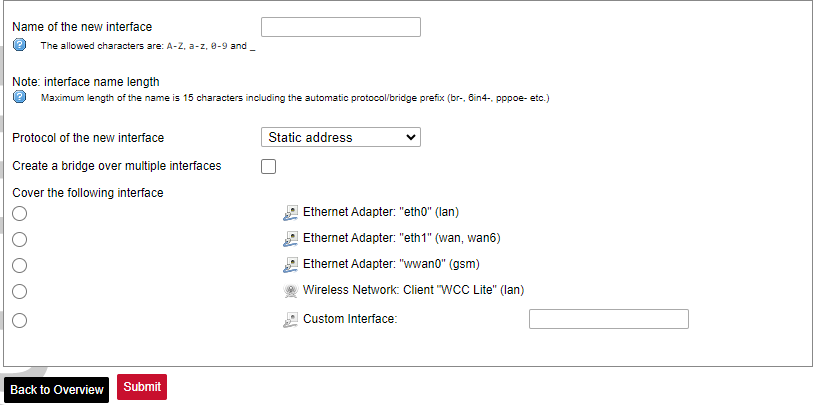](https://wiki.elseta.com/uploads/images/gallery/2023-07/image-1689163491851.png) The following options can be defined in the interface creation panel: name of the interface, protocol, coverage of a particular interface or bridging with other interfaces. After the general setup is done, more detailed settings can be set. [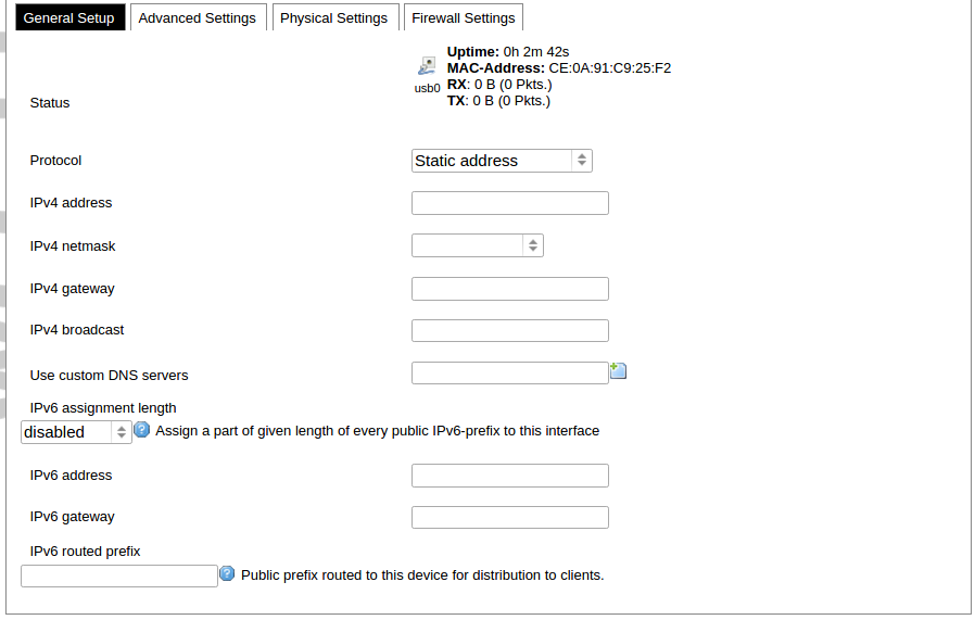](https://wiki.elseta.com/uploads/images/gallery/2020-10/image-1601981923788.png) General common interface setup panel. [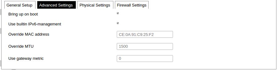](https://wiki.elseta.com/uploads/images/gallery/2020-10/image-1601981938817.png) Advanced common interface setup panel. [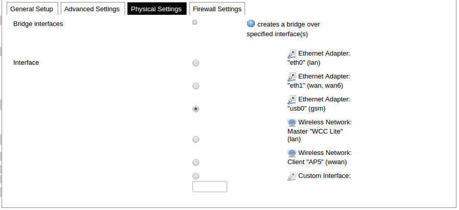](https://wiki.elseta.com/uploads/images/gallery/2020-10/image-1601981952607.png) Physical common interface setup panel. [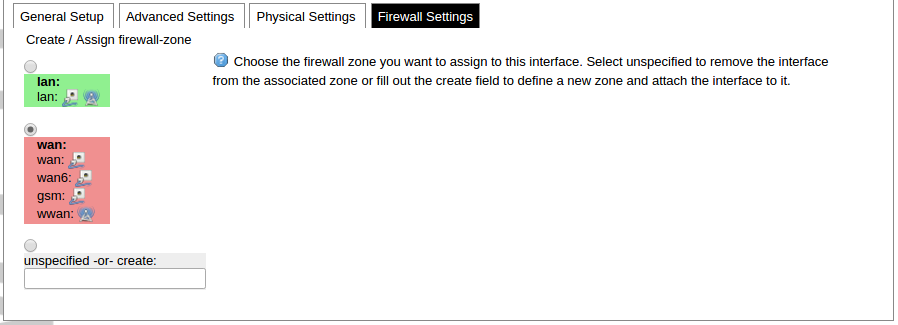](https://wiki.elseta.com/uploads/images/gallery/2020-10/image-1601981969125.png) Firewall common interface setup panel. [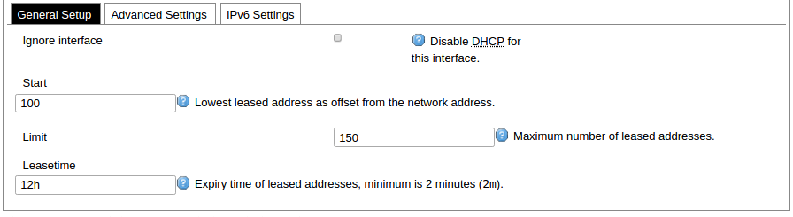](https://wiki.elseta.com/uploads/images/gallery/2020-10/image-1601981983334.png) DHCP server general setup panel. [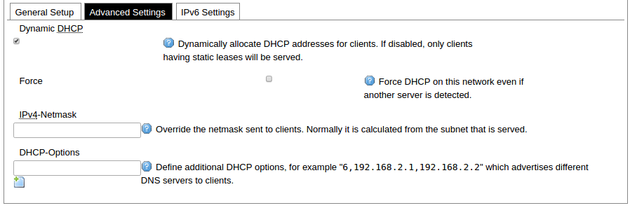](https://wiki.elseta.com/uploads/images/gallery/2020-10/image-1601981997552.png) DHCP server advanced setup panel. [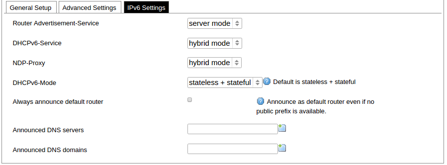](https://wiki.elseta.com/uploads/images/gallery/2020-10/image-1601982015776.png) DHCP server IPv6 settings setup panel. **GSM** [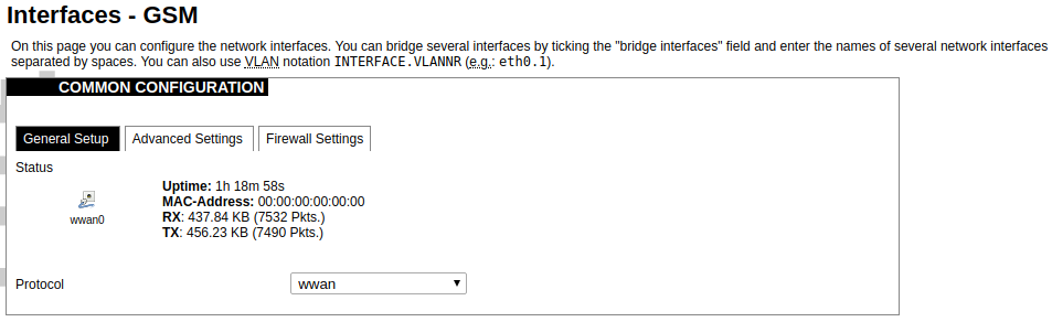](https://wiki.elseta.com/uploads/images/gallery/2020-10/image-1601982038949.png) General Settings Information tab. Gives you the name of the physical GSM interface, and lets you choose the protocol (not recommended!).Note: Make sure you won’t change the GSM interface's protocol, which is set by default to WWAN. Changing this parameter will lead to undefined GSM modem behaviour.
[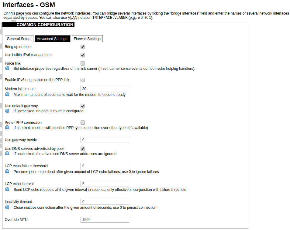](https://wiki.elseta.com/uploads/images/gallery/2020-10/image-1601982122856.png) Advanced Settings tab enables users to configure advanced settings for mobile communication. It includes the following options: Bring up on boot: Checkbox to start a GSM interface on startup; Use built-in IPv6-management: Checkbox to select if the device is going to use its tools to manage IPv6 transport layer messages; Force link: Specifies whether IP address, route, and gateway are assigned to the interface regardless of whether the link is active or only after the link has become active; when active, carrier sense events do not invoke hotplug handlers; IPv6 support: The user can select if IPv6 support is handled automatically, manually or disabled altogether; Modem init timeout: Maximum amount of seconds before the device gives up on finishing initialization; Use default gateway: Uses the default gateway obtained through DHCP. If left unchecked, no default route is configured; Prefer PPP connection: If, the modem, supports PPP and any other communication protocol (e.g. QMI, RNDIS etc.), prioritize PPP type connection; Use gateway metric: The WAN configuration by default generates a routing table entry. In this field, you can alter the metric of that entry. Higher metric means higher priority; Use DNS servers advertised by peer: Uses DNS servers obtained from DHCP. If left unchecked, the advertised DNS server addresses are ignored; LCP echo failure threshold: LCP (link control protocol) is a part of PPP (Point-to-Point Protocol) and helps to determine the quality of data transmission. If enough failures happen, LCP presumes the link to be dead. 0 disables failure count checking; LCP echo interval: Determines the period of LCP echo requests. Only effective if the LCP echo failure threshold is more than zero; Inactivity timeout: Station inactivity limit in seconds: if a station does not send anything, the connection will be dropped. A value of 0 can be used to persist the connection. Override MTU: Set custom MTU to GSM interface.Note: If the modem uses QMI connection protocol and the user hasn’t defined a custom MTU setting, the MTU on the interface will be set to the operator’s defined MTU value.
[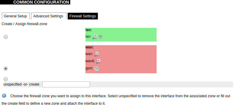](https://wiki.elseta.com/uploads/images/gallery/2020-10/image-1601982419586.png) GSM configuration ends with firewall settings. A user can assign an already-defined firewall zone or create a new one. ### Wireless The wireless network interface parameters and configuration are described in this section. [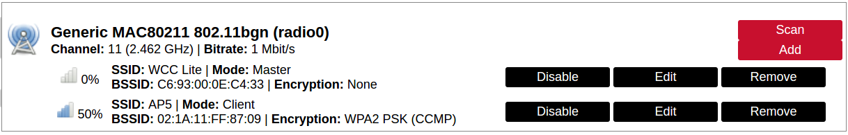](https://wiki.elseta.com/uploads/images/gallery/2020-10/image-1601982558981.png) Configured interfaces for the physical radio device. Channel: Specifies the wireless channel to use. Bitrate: Specifies transfer rate in Mbit/s. SSID: The broadcasted service set identifier of the wireless network. Mode: Select the operation mode of the wireless network interface controller. BSSID: The basic service set identification of the network, only applicable in ad-hoc or STA mode. Encryption: Wireless encryption method. [](https://wiki.elseta.com/uploads/images/gallery/2020-10/image-1601982595431.png) List of associated wireless stations. The Device Configuration section covers the physical settings of the radio hardware such as channel, transmit power or antenna selection which are shared among all defined wireless networks (if the radio hardware is multi-SSID capable). Network settings like encryption or operation mode are grouped in the Interface Configuration. [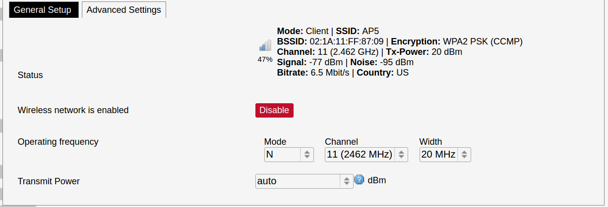](https://wiki.elseta.com/uploads/images/gallery/2020-10/image-1601982626129.png) General device settings. [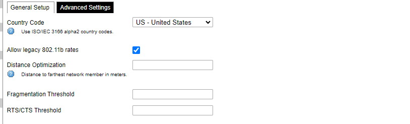](https://wiki.elseta.com/uploads/images/gallery/2023-07/image-1689164526938.png) Advanced device settings. [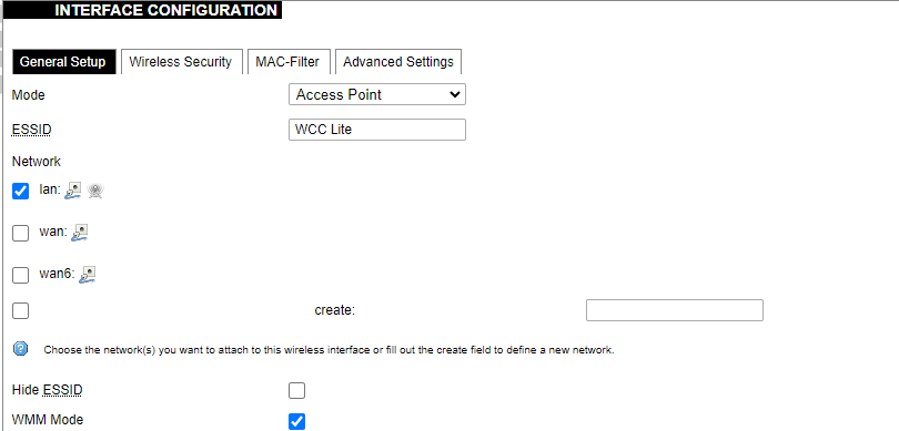](https://wiki.elseta.com/uploads/images/gallery/2023-07/image-1689164604885.png) General interface settings. [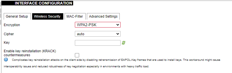](https://wiki.elseta.com/uploads/images/gallery/2023-07/image-1689164644127.png) Wireless security interface settings. [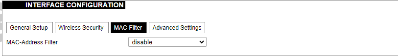](https://wiki.elseta.com/uploads/images/gallery/2023-07/image-1689164733815.png) MAC-Filter settings. [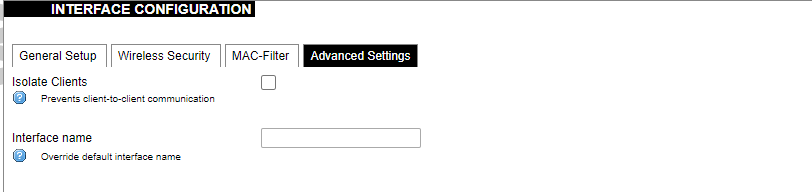](https://wiki.elseta.com/uploads/images/gallery/2023-07/image-1689164771647.png) Advanced interface settings. ### DHCP and DNS DHCP server and DNS forward for NAT firewalls are described in this section. [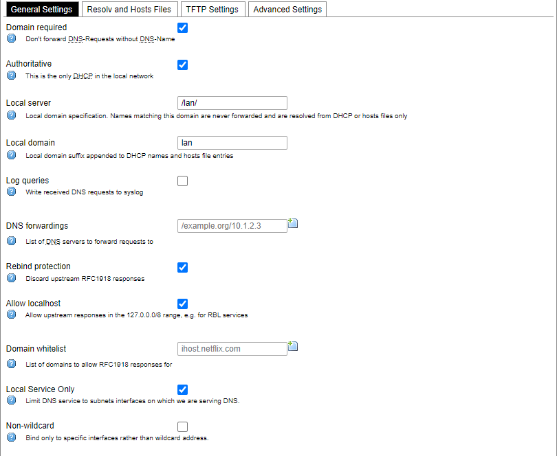](https://wiki.elseta.com/uploads/images/gallery/2023-07/image-1689164834063.png) General DHCP settings. [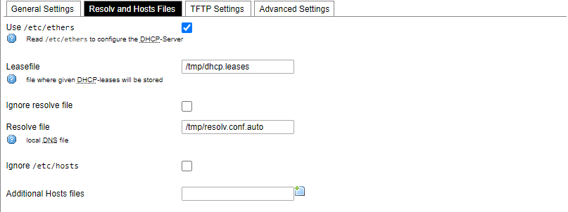](https://wiki.elseta.com/uploads/images/gallery/2023-07/image-1689164924689.png) Resolve and host file settings. [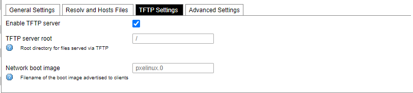](https://wiki.elseta.com/uploads/images/gallery/2023-07/image-1689164959749.png) TFTP server settings. [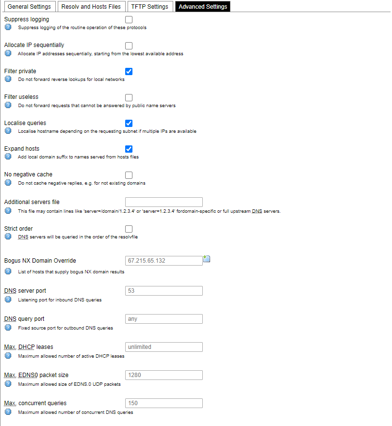](https://wiki.elseta.com/uploads/images/gallery/2023-07/image-1689164984452.png) Advanced settings. [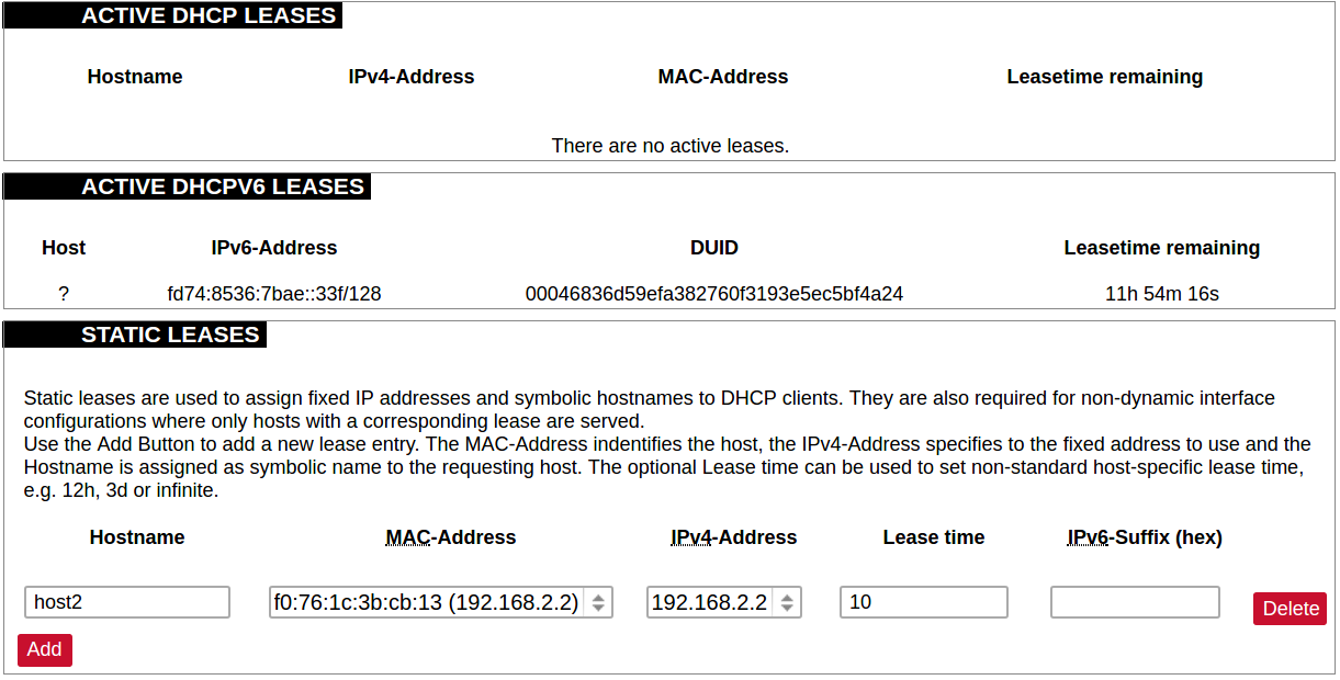](https://wiki.elseta.com/uploads/images/gallery/2020-10/image-1601982769138.png) List of active DHCP and static leases. It is also possible to assign fixed IP addresses to hosts on the network, based on their MAC (hardware) address. ### Hostnames [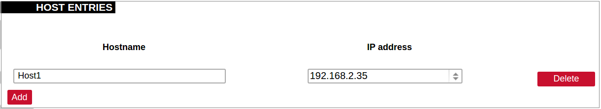](https://wiki.elseta.com/uploads/images/gallery/2020-10/image-1601983068649.png) List of existing host names. Addition or deletion is allowed for the user. ### Static routes Routes specify over which interface and gateway a certain host or network can be reached. [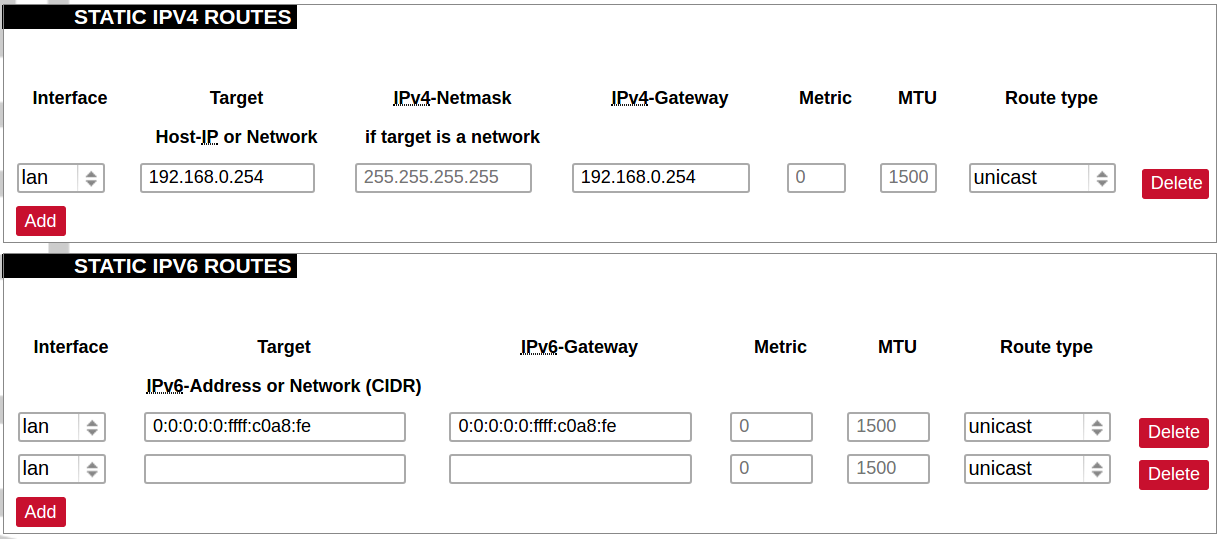](https://wiki.elseta.com/uploads/images/gallery/2020-10/image-1601983099686.png) Current IPv4 and IPv6 static routes configuration. Interface: Let to choose for which interface static route is created. Target: Defines target host IP or network. IPv4 Netmask: Defines netmask if the target is a network. IPv4/IPv6 Gateway: Defines IPv4 or IPv6 gateway. Metric: Specifies the route metric to use for the route. MTU: Maximum Transmit/Receive Unit, in bytes. Route type: All incoming packets can be: accepted, rejected, or dropped. ### Diagnostics [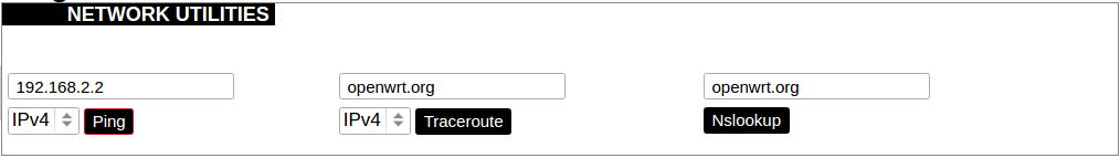](https://wiki.elseta.com/uploads/images/gallery/2020-10/image-1601983517039.png) Diagnostics tools which can be used to diagnose some of the networking problems: ping, traceroute and nslookup. ### Firewall This subsection is divided into four categories: general settings, port forwards, traffic rules and custom rules. #### General settings [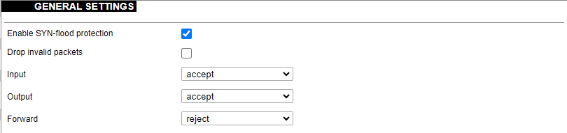](https://wiki.elseta.com/uploads/images/gallery/2023-07/image-1689165180227.png) General firewall settings can be changed in the General Settings screen. These settings are defined as follows: Input: All incoming packets can be: accepted, rejected, or dropped. Output: All outgoing packets can be: accepted, rejected, or dropped. Forward: All packets being sent to another device can be: accepted, rejected, or dropped. [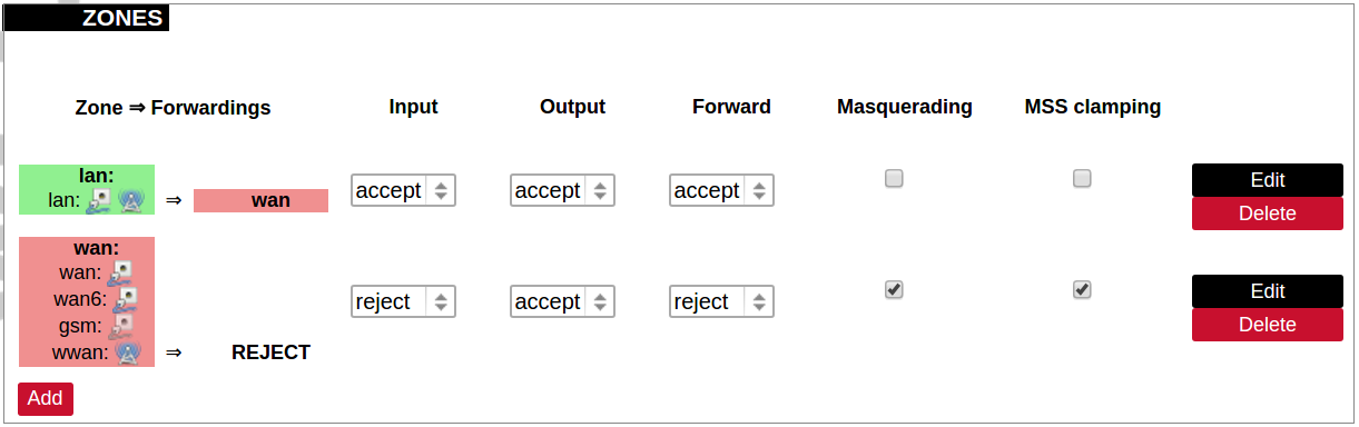](https://wiki.elseta.com/uploads/images/gallery/2020-10/image-1601983200596.png) Additional zones for the firewall can be created, edited or deleted. Zone => Forwardings: Defines zones and their traffic flow. Input: All incoming packets can be: accepted, rejected, or dropped. Output: All outgoing packets can be: accepted, rejected, or dropped. Forward: All packets being sent to another device can be: accepted, rejected, or dropped. Masquerading: Allows one or more devices in a zone network without assigned IP addresses to communicate with the Internet. MSS clamping: Change the maximum segment size (MSS) of all TCP connections passing through this zone with MTU lower than the Ethernet default of 1500.Additional actions can be performed with zones: add, edit, delete.
[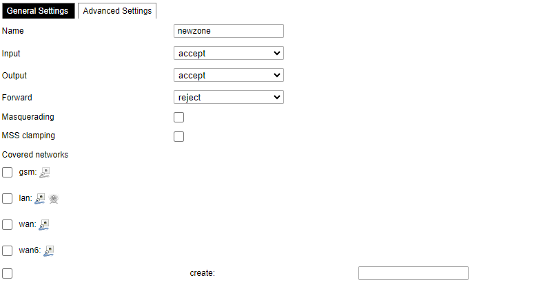](https://wiki.elseta.com/uploads/images/gallery/2023-07/image-1689165259861.png) Common properties of newly created or edited zones can be edited in this panel. The input and output options set the default policies for traffic entering and leaving this zone while the forward option describes the policy for forwarded traffic between different networks within the zone. Covered networks specify which available networks are members of this zone. [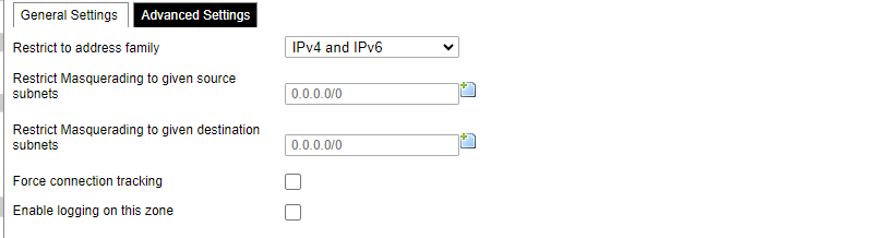](https://wiki.elseta.com/uploads/images/gallery/2023-07/image-1689165330491.png) Advanced settings of newly created or edited zones. Restrict to address family option defines to what IP families the zone belongs to IPv4, IPv6 or both. Restrict masquerading to given source/destination subnets defines one or more subnets for which the masquerading option is applied. Connection tracking and logging options enable additional information gathering on the zone. [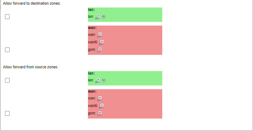](https://wiki.elseta.com/uploads/images/gallery/2023-07/image-1689165393653.png) Controls the forwarding policies between new/edited zone and other zones. Destination zones cover forwarded traffic originating from the new/edited zone. Source zones match forwarded traffic from other zones targeted at the new/edited zone. The forwarding rule is unidirectional, e.g. a forward from LAN to WAN does not imply permission to forward from WAN to LAN as well. #### Port forwards [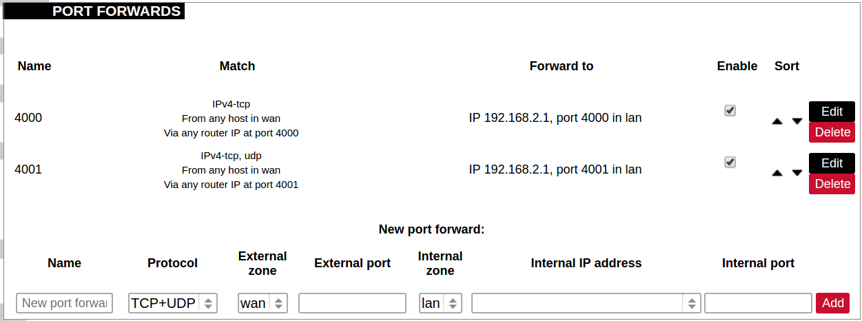](https://wiki.elseta.com/uploads/images/gallery/2020-10/image-1601983338573.png) Port forwarding allows remote computers on the Internet to connect to a specific computer or service within the private LAN. It is done in a way of routing network packets within a private network created by the device. Settings for the port forwarding of the device are defined as follows: Name: The name of the port forwarding rule. Match: Informs what port forward is matched to. Forward to: Informs where the port is forwarded to. Enable: Enable (checked) or disable port forward. Sort: Allows to sort port forwarding. The user can add, edit or delete port forwarding rules. #### Traffic rules [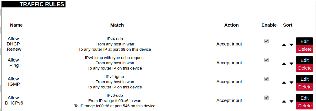](https://wiki.elseta.com/uploads/images/gallery/2020-10/image-1601983387128.png) Traffic rules define policies for packets travelling between different zones. Name: The name of the traffic rule. Match: Informs what ICMP types are matched. Action: Informs what action would be performed. Enable: Enable (checked) or disable the rule. Sort: Allows to sort rules. The user can add, edit or delete traffic rules. Every rule can be defined by these options: name, restrict to address family, protocol, match ICMP type, source and destination zones, source MAC, IP addresses and port, destination IP address and port, action and extra arguments, month and weekdays for which rule will apply, start/stop dates and times, time in UTC. [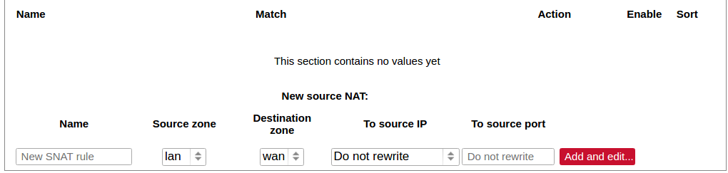](https://wiki.elseta.com/uploads/images/gallery/2020-10/image-1601983450903.png) Source NAT is a specific form of masquerading which allows fine-grained control over the source IP used for outgoing traffic, for example, to map multiple WAN addresses to internal subnets. The user can add, edit or delete source NAT rules. For every rule can be defined these options: name, protocol, source and destination zones, source, destination, SNAT IP addresses, ports, extra arguments, month and weekdays for which rule will apply, start/stop dates and times, time in UTC. #### Custom rules [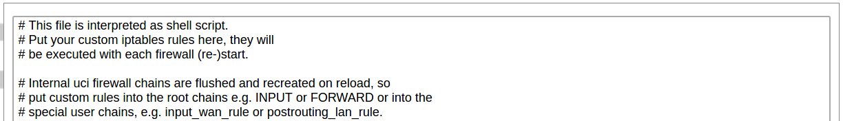](https://wiki.elseta.com/uploads/images/gallery/2020-10/image-1601983486025.png) Custom rules allow the execution of arbitrary iptables commands which are not otherwise covered by the firewall framework. The commands are executed after each firewall restart, right after the default ruleset has been loaded. ### GSM #### Gsm settingsNote: If you have a WCC Lite without a modem, the GSM tab will still be visible, but these changes won't affect anything.
Note: From FW version 1.9.1 Pinger is disabled by default.
[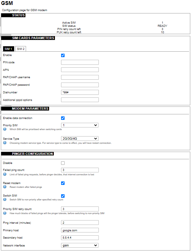](https://wiki.elseta.com/uploads/images/gallery/2023-07/image-1689165599853.png) #### SIM cards parameters Parameters for SIM card. If a single SIM modem is used, there won’t be ”SIM 1” and ”SIM 2” tabs. Enable: Enable or disable this SIM card. PIN code: PIN code to use on that SIM card. APN: APN to use on that SIM car. PAP/CHAP username: Username (optional). PAP/CHAP password: Password (optional). #### Modem parameters Enable data connection: Enable or disable data connection through a GSM modem. Priority SIM: Primary SIM card (if Dual SIM modem is used). Mainly used for pinger configuration. Service Type: Which radio access technology will be used when connecting to the GSM network. Each modem has different available preset RAT options, that can be selected in the drop-down menu. #### Pinger configuration Pinger is a service which pings defined hosts to check internet connection. If both of these hosts are unreachable pinger will wait and restart the modem (or switch SIM card, if Dual-SIM modem is installed in WCC Lite) Disable: Disable pinger functionality. Failed ping count: Limit of failed ping requests, before the pinger decides that the internet connection is lost. Reset modem: If checked, pinger resets the gsm modem after ”Failed ping count”. Switch SIM: If checked, pinger switches SIM to non-priority after ”Priority SIM retry count”. If an internet connection is not available with a non-priority SIM as well, the pinger switches back to a priority SIM after one failed ping attempt. Priority SIM retry count: How many blocks of failed pings will the pinger tolerate, before switching to non-priority SIM. Ping interval (minutes): Interval between ping requests. Primary host: The host that will be pinged first. Secondary host: The host that will be pinged second, if the primary host fails. Network interface: GSM network interface name.GSM Pinger is used to detect the status of network connections via cellular networks. This status is written to file (/var/run/board/internet-status) and can be configured to be sent to SCADAs. If the pinger is disabled, the status is always set equal to zero and should not be trusted to represent internet status. Additionally, this status is reflected in the ”Status”-> “GSM Status” window.
This is Pinger functionality described step by step: • Pinger will ping the primary host every 2 minutes. • If the primary host fails, the pinger redirects to the secondary host immediately. • If either the primary or secondary host is responding to ping requests, the pinger will continue testing the connection with every ”Ping interval (minutes)” parameter and no further action is taken. • If both primary and secondary hosts are unreachable, the pinger will start pinging these hosts every ”Ping interval (minutes) / 2” minute for ”Failed ping count” times. • If hosts are still unreachable, the pinger will try to switch SIM and restart the modem (if corresponding parameters are set) or will restart immediately if a single SIM modem is used. • SIM card is switched to non-priority SIM after ”Priority SIM retry count” failed modem restarts with priority SIM. If a non-priority SIM fails, it is switched to a priority SIM in the next pinger action. #### Dual SIM start procedure The table below shows, which card is expected on boot when a selection is made between Enable/Disable SIM cards and Primary card.| SIM 1 Enabled | SIM 2 Enabled | Priority SIM | SIM on boot |
| X | 1 | 1 | |
| X | 2 | 1 | |
| X | 1 | 2 | |
| X | 2 | 2 | |
| X | X | 1 | 1 |
| X | X | 2 | 2 |
| 1 | Undefined | ||
| 2 | Undefined |
SMS logging is available from firmware version 1.9.1
Here the user can find all the messages that were sent to the device. It shows the time that the message was received, the sender's phone number and the text sent. The SIM card column shows to which SIM card (1 or 2) was the message sent. [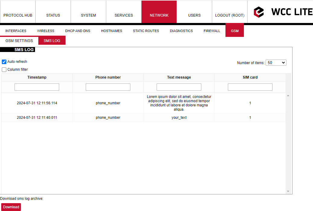](https://wiki.elseta.com/uploads/images/gallery/2024-07/image-1722428314941.png) ### Layer 2 Tunneling Protocol In computer networking, Layer 2 Tunneling Protocol (L2TP) is a tunnelling protocol used to support virtual private networks (VPNs) or as part of the delivery of services by ISPs. It does not provide any encryption or confidentiality by itself. Rather, it relies on an encryption protocol that it passes within the tunnel to provide privacy. #### Description The entire L2TP packet, including payload and L2TP header, is sent within a User Datagram Protocol (UDP) datagram. It is common to carry PPP sessions within an L2TP tunnel. L2TP does not provide confidentiality or strong authentication by itself. IPsec is often used to secure L2TP packets by providing confidentiality, authentication and integrity. The combination of these two protocols is generally known as L2TP/IPsec (discussed below). The two endpoints of an L2TP tunnel are called the LAC (L2TP Access Concentrator) and the LNS (L2TP Network Server). The LNS waits for new tunnels. Once a tunnel is established, the network traffic between the peers is bidirectional. To be useful for networking, higher-level protocols are then run through the L2TP tunnel. To facilitate this, an L2TP session (or ’call’) is established within the tunnel for each higher-level protocol such as PPP. Either the LAC or LNS may initiate sessions. The traffic for each session is isolated by L2TP, so it is possible to set up multiple virtual networks across a single tunnel. MTU should be considered when implementing L2TP. The packets exchanged within an L2TP tunnel are categorized as either control packets or data packets. L2TP provides reliability features for the control packets, but no reliability for data packets. Reliability, if desired, must be provided by the nested protocols running within each session of the L2TP tunnel. L2TP allows the creation of a virtual private dialup network (VPDN) to connect a remote client to its corporate network by using a shared infrastructure, which could be the Internet or a service provider’s network. #### Setting up the L2TP interface To create an L2TP tunnel following steps are required: 1\. Go to **Network > Interfaces > Add new interface:** [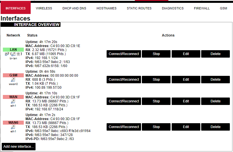](https://wiki.elseta.com/uploads/images/gallery/2023-07/image-1689167492396.png) 2\. Enter the interface name and select L2TP protocol: [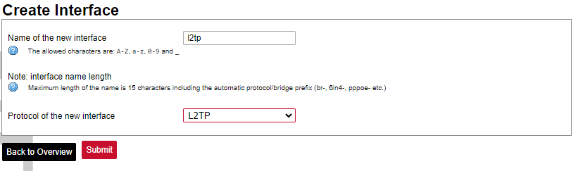](https://wiki.elseta.com/uploads/images/gallery/2023-07/image-1689167536625.png) 3\. Enter the server name and authorization parameters: [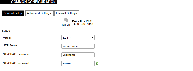](https://wiki.elseta.com/uploads/images/gallery/2020-10/image-1601984049181.png) 4\. Save and apply the new configuration. A new network interface will appear. # 8.8 Users #### Edit groups [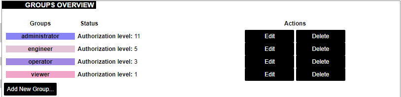](https://wiki.elseta.com/uploads/images/gallery/2023-07/image-1689228768652.png) On this page, user groups can be edited, deleted or added. Groups: name of the user group Status: shows authorization level set to the specific user group. The higher the lever, the higher the authorization requirements. Actions: edit or delete a user group ##### Add new group [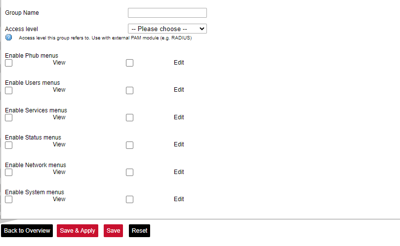](https://wiki.elseta.com/uploads/images/gallery/2023-07/image-1689230250950.png) Configuration window for the new group. After the group name is determined, access level and permissions can be set. #### Edit users [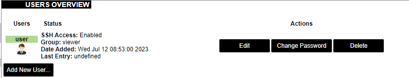](https://wiki.elseta.com/uploads/images/gallery/2023-07/image-1689230967641.png) On the edit users window list of all the users is shown. Users: user name Status: shows if SSH access is enabled and which group the user belongs to. Actions: edit, delete or change the password for the user ##### Add new user[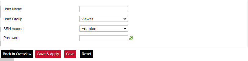](https://wiki.elseta.com/uploads/images/gallery/2023-07/image-1689231760999.png) Configuration window for new users. To create a new user, a name and password should be created and user group and SSH access should be set. #### Password [](https://wiki.elseta.com/uploads/images/gallery/2023-07/image-1689232974821.png) Changes the password of the device. # 8.9 Logout [](https://wiki.elseta.com/uploads/images/gallery/2023-07/image-1689167799567.png) To log out of the device graphical user interface a logout button in the interface’s upper right corner should be pressed. A user is automatically disconnected after ten minutes of inactivity. This ensures that the device would not be suspected of any deliberate damage made by unauthorized access. # 9 API The firmware of the WCC Lite features a built-in API which is accessible via the web interface. The API (as of version 1.2.0) implements API key authorization, that is generated on the first boot of the device. The authorization can be enabled or disabled and the API key can be changed via the web configuration interface at Services → API. ##### Authentication API key authentication is enabled by default and it generates a random 12-character long key. The key is stored in the same uci configuration as API. To change the API key via the interface, it must be equal to or longer than 12 characters. When API authentication is enabled WCC Lite+ checks if the "apiKey" header exists in the request and then validates its value against the one in the configuration. If the value is correct it continues with the API request, if the apiKey is incorrect or doesn't exist it returns an error response 401 with the message. {| Path | Description | Request body (encoded as "multipart-form-data") | Response body example (json format) |
| /api/version | Version of the API | { "api\_version": "2", "api\_patch": "1", "sync\_version": "lite1" } | |
| /api/actions | List of available points | ||
| /api/syncVersion | A version of the sync service | ||
| /api/sync | Protocol hub configuration upload (key name="file"). Returns excel-utility output )\* | { "file": "config.xlsx" } | |
| /api/syslog | Prints out the syslog | ||
| /api/systemInfo | General system info | ||
| /api/gsmInfo | GSM modem information | ||
| /api/devices | List of configured devices | ||
| /api/device/info | Returns configured device information. (key name="device\_alias")\*\* | { "device\_alias": "INV1" } | { "Devices": \[ { "device\_alias": "INV1", "name": "INV1", "protocol": "modbus rtu" } \] } |
| /api/device/tags | List of tags of a particular configured device. (key name="device\_alias")\*\* | {
"device_alias": "INV1"
} | { "total\_signals": "7", "signals": \[ { "signal\_name": "Active power", "source\_device\_alias": "", "input\_topic": "tag/INV1/P/rin", "output\_topic": "tag/INV1/P/out", "signal\_alias": "P" }, ... |
| /api/device/tag/value | Returns tags value, name, timestamp, and flags of a particular device. (key name="device\_alias", key name="signal\_alias")\*\* | { "device\_alias": "INV1", "signal\_alias": "P" } | { "total\_signals": "1", "signal\_values": \[ { "signal\_name": "Active power", "value": "5.9589999999999996", "timestamp": "1708000203824", "flags": "" } \] } |
| /api/tags | List of configured tags | ||
| /api/sysupgrade | Firmware upgrade. (key name="file")\* | { "file": "1.8.0-rtu.sysupgrade" } | If successfully started the upgrade: { "message": "Upgrade started" } If failed to begin: { "message": "Failed to begin upgrade" } If firmware validation failed: { "message": "Failed to validate image" } |
SMS sender functionality is available since firmware version v1.5.4, of WCC Lite.
### Configuring SMS sender To configure WCC Lite to use SMS sender and user must fill in the needed parameters in Excel configuration. These parameters are shown in the tables below. *SMS sender parameters for Devices tab:*| **Parameter** | **Type** | **Description** | **Required | **Default value** (when not specified) | **Range** | |
| Min | Max | |||||
| name | string | User-friendly device name | Yes | |||
| description | string | Description of the device | No | |||
| device\_alias | string | Device alias to be used in configuration | Yes | |||
| enable | boolean | Enabling/disabling of a device | No | 1 | 0 | 1 |
| protocol | string | Selection of protocol | Yes | **SMS sender** | ||
| host | array | List of phone numbers to send SMS to, separated by space. | Yes | |||
| **Parameter** | **Type** | **Description** | **Required | **Default value** (when not specified) | **Range** | |
| Min | Max | |||||
| signal\_name | string | User-friendly signal name | Yes | |||
| device\_alias | string | Device alias from a Devices tab | Yes | |||
| signal\_alias | string | Unique signal name to be used | Yes | |||
| source\_device\_alias | string | device\_alias of the source device | No | |||
| source\_signal\_alias | string | source\_alias of the source signal | No | |||
| enable | boolean | Enabling/disabling of a signal | No | 1 | 0 | 1 |
| log | integer | Enable logging in the event log | No | 0 | 0 | |
| job\_todo | string | Specific SMS sender tag type | Yes | send-sms, device-control, device-status | ||
| tag\_job\_todo | string | SMS sender tag for **send-sms**: *text message* | Yes | |||
| trigger | string | Trigger expression for the SMS to be sent | No (Only for send\_sms) | value!=0 | ||
To set up TLS connection for both DNP3 Master and Slave, refer to sections Excel configuration and Certificates. All keys and certificates should be provided in the PEM format.
If no configuration is set up, DNP3 Master and Slave services are not started.
# 12.2 DNP 3.0 Master Default groups and variation sets are used to send commands. If slave devices support different groups and variations, they can be adjusted in Excel configuration. For more information check section [Excel configuration](https://wiki.elseta.com/books/manual/chapter/18-excel-configuration). #### Configuring data points To use DNP3 Master in WCC Lite, it has to be configured via an Excel configuration. This configuration contains two Excel sheets where parameters have to be filled in Devices and Signals. ##### DNP3 Master parameters for Devices tab| **Parameter** | **Type** | **Description** | **Required** | **Default Value** (when not specified) | **Range** | ||
|---|---|---|---|---|---|---|---|
| TCP/ TLS | Serial | Min | Max | ||||
| name | string | User-friendly device name | Yes | Yes | |||
| description | string | Description of a device | No | No | |||
| device\_alias | string | Alphanumeric string to identify a device | Yes | Yes | |||
| enable | boolean | Enabling/disabling of a device | No | No | 1 | 0 | 1 |
| protocol | string | Protocol to be used (”dnp3 serial”/”dnp3 tcp” (case insensitive)) | Yes | Yes | DNP3 TCP, DNP3 serial | ||
| mode | string | Choosing between TCP, TLS and SERIAL modes. If the protocol provided DNP3 TCP mode defaults to tcp and if DNP3 serial is provided mode defaults to serial | No | No | TCP (for DNP3 TCP) SERIAL (for DNP3 serial) | TCP, TLS (for DNP3 TCP) SERIAL (for DNP3 serial) | |
| host | string | The IP address of the TCP slave device | Yes | - | |||
| bind\_address | string | The IP address of the network adapter used to connect to the slave device | No | No | 0.0.0.0 | ||
| port | integer | TCP communication port | No | No | 20000 | ||
| device | integer | Communication port (”PORT1” or ”PORT2”) | - | Yes | |||
| baudrate | integer | Communication speed, bauds/s | - | No | 9600 | 300, 600, 1200, 2400, 4800, 9600, 19200, 38400, 57600,115200 | |
| databits | integer | Data bit count for communication | - | No | 8 | 6 | 9 |
| stopbits | integer | Stop bit count for communication | - | No | 1 | 1 | 2 |
| parity | string | Communication parity option | - | No | none | none, even, odd | |
| flowcontrol | string | Communication device flow control option. | - | No | none | none | |
| tls | boolean | Enable/disable the use of TLS | Yes (for TLS) | - | 0 | 0 | 1 |
| tls\_local\_certificate | string | Local certificate for TLS connection | Yes (for TLS) | - | |||
| tls\_peer\_certificate | string | Certificate authority file for TLS connection | No (for TLS) | - | |||
| tls\_private\_key | string | A file consisting of the private key for TLS connection | No (for TLS) | - | |||
| max\_rx\_frag\_size | integer | Maximum size of a received fragment. | No | No | 2048 | 0 | 2048 |
| destination\_address | integer | Address of a master station | No | No | 1 | 0 | 65535 |
| source\_address | integer | Address of a slave (local) station. | No | No | 1 | 0 | 65535 |
| unsol\_classes | string | Defines which classes will have unsolicited actions on startup. (Example: "1,3,2") | No | No | no class | 1 | 3 |
| unsol\_disable | bool | Disables unsolicited messages on startup. The parameter is going to be ignored if the unsol\_classes parameter has any values assigned. | No | No | 0 | 0 | 1 |
| groups\_scan\_mask | integer | Bitmask for enabling separate group scans with x06 qualifier (all objects). The parameter value is converted into a binary number where each bit stands for a separate group. Bits indexes and the groups that they represent: 0 - Binary, 1 - Doublebit Binary, 2 - Binary Output Status, 3 - Counter, 4 - Frozen Counter, 5 - Analog, 6 - Analog Output Status, 7 - Octet String (Example: 115 (0111 0011) will trigger data polls for signals whose types are - Binary, Doublebit Binary, Frozen Counter, Analog, Analog Output Status) | No | No | 0 | 0 | 255 |
| groups\_scan\_interval | integer, string | The time between separate groups scans intervals in seconds. Set to 0 to disable. | No | No | 0 | 0 | |
| exception\_scan\_interval | integer, string | The time between exception scan (classes 1,2,3) intervals in seconds. Set to 0 to disable. | No | No | 0 | 0 | |
| integrity\_scan\_interval | integer, string | Time between integrity scan (classes 0,1,2,3) intervals in seconds (general interrogation). Set to 0 to disable. | No | No | 0 | 0 | |
| timesync\_mode | string | Will override the master default setting for choosing the time sync procedure | No | No | NON-LAN (for Serial) LAN (for tcp) | LAN, NON-LAN | |
| time\_sync\_interval\_sec | integer, string | Periodic time sync interval in seconds. If > 0 - time syncs are forced and periodic. If = 0 - time syncs react to IIN bits from the slave. If < 0 - time syncs are disabled. | No | No | |||
| select\_ms | integer | Select command timeout. Valid for all signals. | No | No | 10000 | ||
| timeout\_ms | integer | Response timeout in milliseconds | No | No | 2000 | ||
| keep\_alive\_timeout | integer | The time interval for sending a keep-alive packet in seconds. | No | - | 60 | ||
| use\_local\_time | boolean | if enabled (1) communication uses system time instead of UTC. | No | No | 0 | 0 | 1 |
| **Parameter** | **Type** | **Description** | **Required** | **Default Value** (when not specified) | **Range** | ||
|---|---|---|---|---|---|---|---|
| TCP | RTU | Min | Max | ||||
| signal\_name | string | User-friendly signal name | Yes | Yes | |||
| device\_alias | string | Device alias from a Devices tab | Yes | Yes | |||
| signal\_alias | string | Unique alphanumeric name of the signal to be used | Yes | Yes | |||
| enable | boolean | Enabling/disabling a device | No | No | 1 | 0 | 1 |
| index | integer | Index of a signal. | Yes | Yes | 0 | 65535 | |
| log | boolean | Enable logging in the event log | No | No | 0 | 0 | 1 |
| signal\_type | string | DNP3 signal type. (case insensitive) | Yes | Yes | ”binary”, ”doublebitbinary”, ”binaryoutputstatus”, ”binaryoutputcommand”, ”counter”, ”frozencounter”, ” analogue”, ”analogoutputstatus”, ”analogoutputcommand”, ”timeandinterval”, ”octetstring” | ||
| command\_variation | integer | DNP3 command variation. *Supported variations depend on signal type and are provided in the table below* | Yes (for commands) | Yes (for commands) | 0 | 4 | |
| static\_variation | integer | DNP3 command variation (). Supported variations depend on signal type and are provided in the table below. | Yes (for read signals) | Yes (for read signals) | 0, 1, 2, 3, 4, 5, 6, 9, 10 | ||
| event\_variation | integer | DNP3 command variation. Supported variations depend on signal type and are provided in the table below. | Yes (for read signals) | Yes (for read signals) | 0 | 8 | |
| control\_code | string | DNP3 control model code of CROB signal. TripClose and Pulse control model requires **PulseOn/off** times to be set | No | No | LATCH, PULSE, TRIPCLOSE | ||
| pulse\_on\_time\_ms | integer | Pulse ON time in milliseconds, when using Pulse or TripClose control models must be set | Yes (for binary PULSE and TRIPCLOSE command codes) | Yes (for binary PULSE and TRIPCLOSE command codes) | |||
| pulse\_off\_time\_ms | integer | Pulse OFF time in milliseconds, when using Pulse or TripClose control models must be set | Yes (for binary PULSE and TRIPCLOSE command codes) | Yes (for binary PULSE and TRIPCLOSE command codes) | |||
| class\_num | integer | Class assignment of the signal. | No | No | 0 | 0 | 3 |
| operate\_type | integer | Default command behaviour. If selected: ”**-1**” - DirectOperateNoAck (FC=6), **”0”** - DirectOperate (FC=5), "**1"** - SelectBeforeOperate (FC=3). | No | No | 1 | -1 | 1 |
| job\_todo | string | The device status signal can be configured by providing one of the given values. | No | No | communication\_status, device\_running, device\_error, unknown\_error | ||
| Signal Type | Available Command Variation | Default Command Variation |
| Binary Output Command (Group12) | 0, 1 | 1 |
| Analog Output Command (Group41) | 0, 1, 2, 3, 4 | 1 |
| Signal Type | Available Variations | Default Variations |
| Binary | Static variation (Group1) 1, 2 Event variation (Group2) 1, 2, 3 | Static variation 2 Event variation 1 |
| Double Binary | Static variation (Group3) 2 Event variation (Group4) 1, 2, 3 | Static variation 2 Event variation 1 |
| Binary Output Status | Static variation (Group10) 1, 2 Event variation (Group11) 1, 2 | Static variation 2 Event variation 1 |
| Counter | Static variation (Group20) 1, 2, 5, 6 Event variation (Group22) 1, 2, 5, 6 | Static variation 1 Event variation 1 |
| Frozen Counter | Static variations (Group21) 1, 2, 5, 6, 9,10 Event variation (Group23) 1, 2, 5, 6 | Static variation 1 Event variation 1 |
| Analog | Static variation (Group30) 1, 2, 3, 4, 5, 6 Event variation (Group32) 1, 2, 3, 4, 5, 6, 7, 8 | Static variation 1 Event variation 1 |
| Analog Output Status | Static variation (Group40) 1, 2, 3, 4 Event variation (Group42) 1, 2, 3, 4, 5, 6, 7, 8 | Static variation 1 Event variation 1 |
| Time and Interval | Static variation (Group50) 1 | Static variation 1 |
| Octet String | Static variation (Group110) 0 Event variation (Group111) 0 | Static variation 0 Event variation 0 |
| Option | Description |
| -h \[ –help \] | Display help information |
| -V \[ –version \] | Show version |
| -d <debug level> | Set debugging level |
| -c \[ –config \] | Config path |
| -r \[ –redis \] | Show Redis messages |
| **Parameter** | **Type** | **Description** | **Required** | **Default Value** (when not specified) | **Range** | ||
|---|---|---|---|---|---|---|---|
| TCP/ TLS | RTU | Min | Max | ||||
| name | string | User-friendly device name | Yes | Yes | |||
| description | string | Description of a device | No | No | |||
| device\_alias | string | Alphanumeric string to identify a device | Yes | Yes | |||
| enable | boolean | Enabling/disabling of a device | No | No | 1 | 0 | 1 |
| protocol | string | Protocol to be used. | Yes | Yes | dnp3 tcp slave dnp3 serial slave | ||
| mode | string | Choosing between TCP, TLS and SERIAL modes. If the protocol is provided DNP3 TCP mode defaults to tcp and if DNP3 serial is provided mode defaults to SERIAL | No | No | TCP or SERIAL | TCP, SERIAL, TLS | |
| host | string | The IP address of the TCP slave device | Yes | - | |||
| bind\_address | string | The IP address of the network adapter used to connect to the slave device | No | - | 0.0.0.0 | ||
| port | integer | TCP communication port | No | - | 20000 | ||
| device | string | Communication port (”PORT1” or ”PORT2”) | - | Yes | |||
| baudrate | integer | Communication speed, bauds/s | - | No | 9600 | 300, 600, 1200, 2400, 4800, 9600, 19200, 38400, 57600,115200 | |
| databits | integer | Data bit count for communication | - | No | 8 | 6 | 9 |
| stopbits | integer | Stop bit count for communication | - | No | 1 | 1 | 2 |
| parity | string | Communication parity option | - | No | none | none, even, odd | |
| flowcontrol | string | Communication device flow control option. | - | No | none | none | |
| tls | boolean | Enable/disable the use of TLS | Yes (for TLS) | - | 0 | 0 | 1 |
| tls\_local\_certificate | string | Local certificate for TLS connection | Yes (for TLS) | - | |||
| tls\_peer\_certificate | string | Certificate authority file for TLS connection | No (for TLS) | - | |||
| tls\_private\_key | string | A file consisting of the private key for TLS connection | No (for TLS) | - | |||
| max\_tx\_frag\_size | integer | Maximum size of a received fragment. | No | No | 2048 | 0 | 2048 |
| destination\_address | integer | Address of a master station | No | No | 1 | 0 | 65535 |
| source\_address | integer | Address of a slave (local) station. | No | No | 1 | 0 | 65535 |
| unsol\_classes | string | Defines which classes will have unsolicited actions on startup. (Example: "1,3,2") | No | No | no class | 1 | 3 |
| time\_sync\_interval\_sec | integer, string | Periodic time sync interval in seconds. If 0 < - time syncs are forced and periodic. If = 0 - time syncs react to IIN bits from the slave. If < 0 - time syncs are disabled. | No | No | 0 | 0 | |
| select\_ms | integer | Select command timeout. Valid for all signals. | No | No | 10000 | ||
| timeout\_ms | integer | Response timeout in milliseconds | No | No | 2000 | ||
| keep\_alive\_timeout | integer | The time interval for sending a keep-alive packet in seconds. | No | No | 60 | ||
| **Parameter** | **Type** | **Description** | **Required** | **Default Value** (when not specified) | **Range** | ||
|---|---|---|---|---|---|---|---|
| TCP | RTU | Min | Max | ||||
| signal\_name | string | User-friendly signal name | Yes | Yes | |||
| device\_alias | string | Device alias from a Devices tab | Yes | Yes | |||
| signal\_alias | string | Unique alphanumeric name of the signal to be used | Yes | Yes | |||
| enable | boolean | Enabling/disabling of a device | No | No | 1 | 0 | 1 |
| index | integer | Index of a signal. | Yes | Yes | 0 | 65535 | |
| log | boolean | Enable logging in the event log | No | No | 0 | 0 | |
| deadband | integer, string | Deadband for Analog, Analog Output Status, Counter, and Frozen Counter signals. | No | No | 0 | ||
| signal\_type | string | DNP3 signal type. (case insensitive) | Yes | Yes | ”binary”, ”doublebitbinary”, ”binaryoutputstatus”, ”binaryoutputcommand”, ”counter”, ”frozencounter”, ”analog”, ”analogoutputstatus”, ”analogoutputcommand” | ||
| command\_variation | integer | DNP3 command variation. *Supported variations depend on signal type and are provided in the table below* | Yes (for commands) | Yes (for commands) | 0 | 4 | |
| static\_variation | integer | Override default signal’s static variation. Valid for Status mode signals. | Yes (for read signals) | Yes (for read signals) | 0, 1, 2, 3, 4, 5, 6, 9, 10 | ||
| event\_variation | integer | Override default signal’s event variation. Valid for Status mode signals. | Yes (for read signals) | Yes (for read signals) | 0 | 8 | |
| class\_num | integer | Class assignment of this signal. | No | No | 0 | 0 | 3 |
| operate\_type | integer | Default command behaviour. If selected: ”**-1**” - DirectOperateNoAck (FC=6), **”0”** - DirectOperate (FC=5), "**1"** - SelectBeforeOperate (FC=3). | No | No | 1 | -1 | 1 |
| job\_todo | string | The device status signal can be configured by providing one of the given values. | No | No | communication\_status, device\_running, device\_error, unknown\_error | ||
| Signal Type | Available Command Variation | Default Command Variation |
| Binary Output Command (Group12) | 0, 1 | 1 |
| Analog Output Command (Group41) | 0, 1, 2, 3, 4 | 1 |
| Signal Type | Available Variations | Default Variations |
| Binary | Static variation (Group1) 1, 2 Event variation (Group2) 1, 2, 3 | Static variation 2 Event variation 1 |
| Double Binary | Static variation (Group3) 2 Event variation (Group4) 1, 2, 3 | Static variation 2 Event variation 1 |
| Binary Output Status | Static variation (Group10) 2 Event variation (Group11) 1, 2 | Static variation 2 Event variation 1 |
| Counter | Static variation (Group20) 1, 2, 5, 6 Event variation (Group22) 1, 2, 5, 6 | Static variation 1 Event variation 1 |
| Frozen Counter | Static variations (Group21) 1, 2, 5, 6, 9,10 Event variation (Group23) 1, 2, 5, 6 | Static variation 1 Event variation 1 |
| Analog | Static variation (Group30) 1, 2, 3, 4, 5, 6 Event variation (Group32) 1, 2, 3, 4, 5, 6, 7, 8 | Static variation 1 Event variation 1 |
| Analog Output Status | Static variation (Group40) 1, 2, 3, 4 Event variation (Group42) 1, 2, 3, 4, 5, 6, 7, 8 | Static variation 1 Event variation 1 |
| Option | Description |
| -h \[ –help \] | Display help information |
| -V \[ –version \] | Show version |
| -d <debug level> | Set debugging level |
| -c \[ –config \] | Config path |
| -r \[ –redis \] | Show Redis messages |
| **Parameter** | **Type** | **Description** | **Required** | **Default Value** (when not specified) | **Range** | ||
|---|---|---|---|---|---|---|---|
| TCP | RTU/ASCII | Min | Max | ||||
| name | string | User-friendly name for a device | Yes | Yes | |||
| description | string | Description of a device | No | No | |||
| device\_alias | string | Alphanumeric string to identify a device | Yes | Yes | |||
| enable | boolean | Enabling/disabling of a device | No | No | 1 | 0 | 1 |
| protocol | string | Protocol to be used | Yes | Yes | Modbus RTU, Modbus TCP | ||
| ip | string | The IP address of the TCP slave device | Yes | - | |||
| port | integer | TCP communication port | Yes | - | 502 | ||
| bind\_address | string | The IP address of the network adapter used to connect to the slave device (Default: ”0.0.0.0”) | No | No | 0.0.0.0 | ||
| id | integer | Modbus Slave ID | Yes | Yes | |||
| mode | string | Choosing between RTU (”rtu”), ASCII (”ascii”) and TCP(”tcp”) modes. ASCII is the same as RTU, but with ASCII symbols. | No | No | TCP (for TCP) RTU (for Serial) | rtu, ascii, tcp | |
| timeout\_ms | integer | Response timeout in milliseconds | No | No | 10000 | ||
| device | string | Communication port (”PORT1”/”PORT2”) | - | Yes | PORT1 | PORT2 | |
| baudrate | integer | Communication speed, baud/s | - | No | 9600 | 300, 600, 1200, 2400, 4800, 9600, 19200, 38400, 57600, 115200 | |
| databits | integer | Data bit count for communication | - | No | 8 | 6 | 9 |
| stopbits | integer | Stop bit count for communication | - | No | 1 | 1 | 2 |
| parity | string | Communication parity option | - | No | none | none, even, odd | |
| flowcontrol | string | Number of requests, before the link is considered lost (device status signals are changed) and reconnect attempt will be issued | - | No | none | none | |
| scan\_rate\_ms | integer | If provided and positive - all jobs will have similar scan rates - all reads and writes will be executed within this timeframe (parameter scan\_rate\_ms in the Signals tab will be ignored) | No | No | 300 | ||
| retry\_count | integer | Number of requests, before the link is considered lost (device status signals are changed) and reconnect attempt will be issued | No | No | 3 | ||
| serial\_delay | integer | RS485 delay between read and write operations in milliseconds | - | No | 50 | ||
| keep\_alive\_timeout | integer | Time interval for sending a keep-alive packet (in seconds) | No | - | 60 | ||
| modbus\_multi\_write | boolean | Use 15/16 functions to write 1 register/coil (Default: 0) | No | No | 0 | 0 | 1 |
| comm\_restart\_delay | integer | Time delay between disconnecting from the slave device and restarting the connection (in milliseconds) (Default: 500) | No | - | 500 | ||
| update | boolean | Enable to keep updating the tags even if they have the same value. | No | No | 0 | 0 | 1 |
| **Parameter** | **Type** | **Description** | **Required** | **Default Value** (when not specified) | **Range** | ||
|---|---|---|---|---|---|---|---|
| TCP | RTU/ASCII | Min | Max | ||||
| signal\_name | string | User-friendly signal name | Yes | Yes | |||
| device\_alias | string | Alphanumeric string to identify a device | Yes | Yes | |||
| signal\_alias | string | Unique alphanumeric name of the signal to be Yes used | Yes | Yes | |||
| enable | boolean | Enabling/disabling of an individual signal | No | No | 1 | 0 | 1 |
| job\_todo | string | Request to send according to Modbus specification without device address and checksum. This field can be identical on several tags to fetch them in a single request | Yes | Yes | |||
| tag\_job\_todo | string | Similar format to the job\_todo field. Address and length must be a subset of the job field. Defines the individual tag’s register(s) or coil(s). Can be described in HEX or DEC formats | Yes | Yes | |||
| number\_type | string | Type of a number. Each allowed type can be prefixed by a single or a combination of swap prefixes (SW8, SW16, SW32), e.g.
SW16.UNSIGNED32, SW32.SW16.SW8.DOUBLE | Yes | Yes | DIGITAL, SIGNED8, UNSIGNED8, SIGNED16, UNSIGNED16, SIGNED32, UNSIGNED32, FLOAT, DOUBLE, SIGNED64, UNSIGNED64 | ||
| log | integer | If the log parameter is 1, the signal will be visible in the events log tab, if 0, signals will not be logged. | No | No | 0 | ||
| pulse\_short\_time\_ms | integer | The time interval for short output pulse to stay active | No | No | 0 | ||
| pulse\_long\_time\_ms | integer | The time interval for a long output pulse to stay active | No | No | 0 | ||
| periodic\_update\_ms | integer | Signal value will be published periodically according to the value set. | No | No | |||
Note: If the number type is more than 16 bits (this means FLOAT, SIGNED32, DOUBLE, etc.), Modbus multiwrite should be enabled (1).
Note: SIGNED64 and UNSIGNED64 number types are only accepted from firmware version 1.11.1. It is also not recommended to use this number type if high precision is required.
##### Device status signals Modbus Master has an additional signal which can be configured to show communication status. It is used to indicate if the slave device has disconnected from the master (WCC Lite). To configure such signal for Modbus protocol, job\_todo field with string value is required. For Modbus master required parameters for the status signal will be: **signal\_name,** **device\_alias, signal\_alias,** and **job\_todo**. Job\_todo must be: **communication\_status.** If the signal returns the value of 1 – the device or protocol connection is on and working correctly, if 2 – the device is off or the protocol is disconnected. Different device vendors can have different implementations of a Modbus protocol stack. A register table can be one of the primary differences. WCC Lite Modbus Master transmits the most significant word (byte) first, however, devices from some vendors might require transmitting the least significant word (byte) first. If that is the case, make sure to switch bytes as needed. To find out more about setting a correct number format, one should consult a section [`number_type`](https://wiki.elseta.com/link/859#bkmrk-number_type-field). Modbus job or tag (as a task to be completed) can be built in two different formats - the user can select a more convenient way for him: - hexadecimal format with every single byte separated by a | symbol. Device address, bytes containing output information and CRC (LRC) bytes should be excluded from the message; - decimal format containing function number, first address and address count, separated by ; symbol. All other information should be excluded from the message; `job_todo` can group several `tag_job_todo`’s. That way one Modbus message can be used to extract several tags. Grouping is accomplished dynamically meaning that if several identical jobs are found, their tags are grouped automatically. #### Debugging a Modbus Master application If the configuration for Modbus Master is set up, a handler for the protocol will start automatically. If the configuration is missing or contains errors, the protocol will not start. It is done intentionally to decrease unnecessary memory usage. Modbus Master command line debugging options `modbus-master ` ``` -h [ –help ] Display help informationIf TCP/IP is used as a transmission medium, only devices with IPs predefined in the host column are allowed to connect. All other connections are rejected
##### Modbus Slave parameters for Devices tab| **Parameter** | **Type** | **Description** | **Required** | **Default Value** (when not specified) | **Range** | ||
|---|---|---|---|---|---|---|---|
| TCP | RTU/ASCII | Min | Max | ||||
| name | string | User-friendly name for a device | Yes | Yes | |||
| description | string | Description of a device | No | No | |||
| device\_alias | string | Alphanumeric string to identify a device | Yes | Yes | unknown | ||
| enable | boolean | Enabling/disabling of a device | No | No | 1 | 0 | 1 |
| protocol | string | Protocol to be used | Yes | Yes | Modbus serial Slave, Modbus TCP Slave | ||
| host | string | Space-separated host IP addresses of master device | Yes | - | |||
| port | integer | TCP port to listen for incoming connections | Yes | - | |||
| bind\_address | string | The IP address of the network adapter used to connect to the slave device (Default: ”0.0.0.0”) | No | No | 0.0.0.0 | ||
| keep\_alive\_timeout | integer | The minimum time a connection can be idle without being closed in seconds | No | No | 60 | ||
| mode | string | Choosing between RTU (”rtu”), ASCII (”ascii”) and TCP(”tcp”) modes. ASCII is the same as RTU, but with ASCII symbols. | No | No | TCP (for TCP) RTU (for Serial) | rtu, ascii, tcp | |
| device | string | Communication port (”PORT1”/”PORT2”) | - | Yes | PORT1 | PORT2 | |
| baudrate | integer | Communication speed, baud/s | - | Yes | 9600 | 300, 600, 1200, 2400, 4800, 9600, 19200, 38400, 57600, 115200 | |
| databits | integer | Data bit count for communication | - | Yes | 8 | 6 | 9 |
| stopbits | integer | Stop bit count for communication | - | Yes | 1 | 1 | 2 |
| parity | string | Communication parity option | - | Yes | none | none, even, odd | |
| flowcontrol | string | The communication device’s flow control option. | - | No | none | none | |
| respond\_delay | integer | Time in milliseconds to wait before sending responses. Disabled if the value is set to 0 | No | No | 0 | 0 | 4294967295 |
| **Parameter** | **Type** | **Description** | **Required** | **Default Value** (when not specified) | **Range** | ||
|---|---|---|---|---|---|---|---|
| TCP | RTU/ASCII | Min | Max | ||||
| signal\_name | string | User-friendly signal name | Yes | Yes | |||
| device\_alias | string | Alphanumeric string to identify a device | Yes | Yes | |||
| signal\_alias | string | Unique alphanumeric name of the signal to be used | Yes | Yes | |||
| enable | boolean | Enabling/disabling an individual signal | No | No | 1 | 0 | 1 |
| number\_type | string | Type of a number (FLOAT, DOUBLE, DIGITAL, etc.). This defines the size that will be read. | Yes | Yes | |||
| log | integer | If the log parameter is equal to 1, the signal values and attributes will be seen in the events log. | No | No | 0 | ||
| slave\_id | integer | Address of a slave device | Yes | Yes | |||
| function | integer | Function number | Yes | Yes | 1, 2, 3, 4 | ||
| register\_address | integer | Register address | Yes | Yes | |||
| periodic\_update\_ms | integer | Signal value is published periodically according to the value set. | No | No | - | - | - |
If a Modbus master device requests data from a register that is mapped but doesn’t yet have an initial value, an ILLEGAL DATA ADDRESS error code will be returned. The same error code is returned if the requested size of the value is bigger than defined or if the register is not configured at all.
#### Debugging a Modbus Slave application If the configuration for Modbus Slave is set up, a handler for the protocol will start automatically. If the configuration is missing or contains errors, the protocol will not start. It is done intentionally to decrease unnecessary memory usage. Modbus Slave command line debugging options To run a debug session: - **Step 1**: Service must be stopped by entering the following command into the wcclite: ``` /etc/init.d/modbus-slave stop ``` - **Step 2**: After the service is stopped it must be started with the preferred configuration file (JSON files found in the /etc/ folder) and a debug level 7: ``` modbus-slave -c /etc/modbus-slave/modbus-slave.json -d7 ``` Additional output forming options described in the table below. - **Step 3**: Once the problem is diagnosed normal operations can be resumed with the following command: ``` /etc/init.d/modbus-slave start ``` ``` -h [ –help ] Display help informationIf Modbus Slave does not work properly (e.g. no communication between devices, data is corrupted, etc.), a user can launch a debug session from the command line interface and find out why the link is not functioning properly.
To launch a debugging session, a user should stop `modbus-slave` process and run `modbus-slave` command with respective flags as shown above.
# 14 IEC 60870-5-10X # 14.1 Introduction **IEC 60870 part 5** is one of the [IEC 60870](https://en.wikipedia.org/wiki/IEC_60870 "IEC 60870") set of standards which define systems used for telecontrol ([supervisory control and data acquisition](https://en.wikipedia.org/wiki/Supervisory_control_and_data_acquisition "Supervisory control and data acquisition")) in [electrical engineering](https://en.wikipedia.org/wiki/Electrical_engineering "Electrical engineering") and [power system automation](https://en.wikipedia.org/wiki/Power_system_automation "Power system automation") applications. Part 5 provides a communication profile for sending basic telecontrol messages between two systems, which uses permanent directly connected data circuits between the systems. The [IEC Technical Committee 57](https://en.wikipedia.org/wiki/IEC_TC_57 "IEC TC 57") (Working Group 03) has developed a [protocol](https://en.wikipedia.org/wiki/Communications_protocol "Communications protocol") standard for telecontrol, teleprotection, and associated telecommunications for [electric power](https://en.wikipedia.org/wiki/Electric_power "Electric power") systems. The result of this work is IEC 60870-5. Five documents specify the base IEC 60870-5: - IEC 60870-5-1 Transmission Frame Formats - IEC 60870-5-2 Data Link Transmission Services - IEC 60870-5-3 General Structure of Application Data - IEC 60870-5-4 Definition and Coding of Information Elements - IEC 60870-5-5 Basic Application Functions - IEC 60870-5-6 Guidelines for conformance testing for the IEC 60870-5 companion standards - IEC TS 60870-5-7 Security extensions to IEC 60870-5-101 and IEC 60870-5-104 protocols (applying IEC 62351) The IEC Technical Committee 57 has also generated companion standards: - IEC 60870-5-101 Transmission Protocols - companion standards especially for basic telecontrol tasks - IEC 60870-5-102 Transmission Protocols - Companion standard for the transmission of integrated totals in electric power systems (this standard is not widely used) - IEC 60870-5-103 Transmission Protocols - Companion standard for the informative interface of protection equipment - IEC 60870-5-104 Transmission Protocols - Network access for IEC 60870-5-101 using standard transport profiles - IEC TS 60870-5-601 Transmission protocols - Conformance test cases for the IEC 60870-5-101 companion standard - IEC TS 60870-5-604 Conformance test cases for the IEC 60870-5-104 companion standard IEC 60870-5-101/102/103/104 are companion standards generated for basic telecontrol tasks, the transmission of integrated totals, data exchange from protection equipment & network access of IEC101 respectively. Source: [https://en.wikipedia.org/wiki/IEC\_60870-5](https://en.wikipedia.org/wiki/IEC_60870-5 "Wikipedia") # 14.2 IEC 60870-5-101 Master The IEC 60870-5-101 protocol is a companion standard for power system monitoring, control associated communications for telecontrol, teleprotection and associated telecommunications for electric power systems. Standard IEC 60870-5-101 was prepared by IEC Technical Committee 57 (Power system control and associated communications). Standard IEC 60870-5-101 defines an **Application Service Data Unit** (**ASDU** Figure below). In ASDU there is an ASDU identifier (with the type of ASDU in it) and information objects.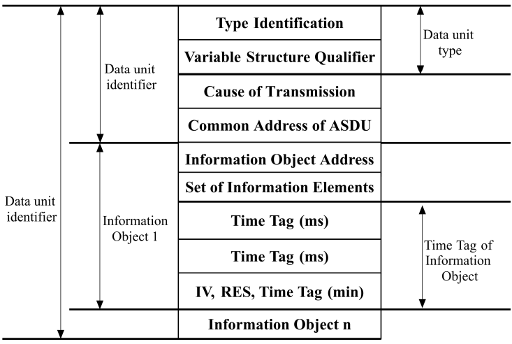 IEC 60870-5-101 ASDU structure **Common Address of ASDU** Defines the stations' address and can be configured in Devices asdu\_address field for source and *Signals* common\_address field for the destination. **Information Object Address** Used as destination object address in the control direction and as source object address in the monitor direction can be configured in the Signals info\_address field. Standard IEC 60870-5-101 transmission frames are separated into 3 different types: **frame with variable length**, **frame with fixed length,** and **single control characters** [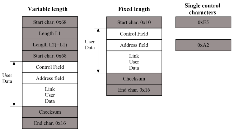](https://wiki.elseta.com/uploads/images/gallery/2021-11/image-1638259001158.png) IEC 60870-5-101 ASDU structure **The control field** provides information about the message direction, type of service, and checksum. **The address field** specifies the link address which points to the message's destination. WCC Lite supports IEC 60870-5-101 Master protocol over a serial link (according to EIA RS485). Its full functionality list can be found in an [IEC 60870-5-101 PID Interoperability List](https://wiki.elseta.com/link/180#bkmrk-pid%27s) which can be downloaded separately from this user manual. ### Configuring datapoints (master) The IEC 60870-5-101 Master in WCC Lite has to be configured in Excel. This configuration contains two Excel sheets where parameters must be filled in Devices and Signals. ##### IEC 60870-5-101 master parameters for *Devices* tab| **Parameter | **Type | **Description | **Required | **Default value** (when not specified) | **Range** | |
| Min | Max | |||||
| name | string | User-friendly name for a device | Yes | |||
| description | string | Description of a device | No | |||
| device\_alias | string | Alphanumeric string to identify a device | Yes | |||
| enable | boolean | Enabling/disabling of a device | No | 1 | 0 | 1 |
| protocol | string | Protocol to be used | Yes | IEC 60870-5-101 master | ||
| device | string | Communication port | Yes | PORT1 | PORT2 | |
| baudrate | integer | Communication speed (bauds/s) | No | 9600 | 600, 1200, 2400, 4800, 9600, 19200, 38400, 57600, 115200 | |
| databits | integer | Data bit count for communication | No | 8 | 6 | 9 |
| stopbits | integer | Stop bit count for communication | No | 1 | 1 | 2 |
| parity | string | Communication parity option | No | none | none, even, odd | |
| flowcontrol | string | Number of requests, before the link is considered lost (device status signals are changed) and reconnect attempt will be issued | No | none | none | |
| link\_address | integer | Destination address when in transmit and source address when broadcasting | Yes | 0 | 65535 | |
| link\_size | integer | Link address size in bytes | No | 1 | 1 | 2 |
| asdu\_address | integer | Application Service Data Unit address | Yes | 0 | 65535 | |
| asdu\_size | integer | Common address size in bytes | No | 1 | 1 | 2 |
| ioa\_size | integer | Information object address (IOA) size in bytes | No | 2 | 1 | 3 |
| cot\_size | integer | Cause of transmission (COT) size in bytes | No | 1 | 1 | 2 |
| time\_sync\_interval\_sec | integer | Defines how often (in seconds) a slave will request time synchronization. **If greater than 0** – slave will request synchronizations and will reset the timer if the master did it earlier. **If 0** – slave won’t request timesyncs, but will allow them. **If 1** – time syncs are not supported, all time sync requests will be dropped. | No | 60 | ||
| broadcast\_timesync | integer | Enables or disables broadcast time sync. **If 0** - disabled **If 1** - enabled | No | 0 | 1 | |
| gi\_interval\_sec | integer | The time frame between General Interrogation requests in seconds if 0 requests are disabled | No | 300 | ||
| scan\_rate\_ms | integer | Polling interval in milliseconds. The time frame between two telegrams from the master | No | 100 | ||
| timeout\_ms | integer | Response timeout in milliseconds | No | 1000 | ||
| retry\_count | integer | Number of retries of failed requests before announcing that the device is in Error state | No | 1 | ||
| **Parameter** | **Type** | **Description** | **Required | **Default value** (when not specified) | **Range** | |
| Min | Max | |||||
| signal\_name | string | User-friendly signal name | Yes | |||
| device\_alias | string | Alphanumeric string to identify a device | Yes | |||
| signal\_alias | string | Unique alphanumeric name of the signal to be used | Yes | |||
| source\_device\_alias | string | device\_alias of a source device | For commands | |||
| source\_signal\_alias | string | signal\_alias of a source signal | For commands | |||
| enable | boolean | Enabling/disabling of an individual signal | No | 1 | 0 | 1 |
| log | integer | Allow signal to be logged. If the **log is 0 signal** will not be logged. If the **log is more than 0** signal will be logged | No | 0 | ||
| gi | boolean | Including/excluding (1 or 0) signals from General Interrogation | No | 0 | 0 | 1 |
| common\_address | integer | Address of a destination device | No | 1 | ||
| info\_address | integer | Information object address | Yes | |||
| data\_type | integer | ASDU type identifier | Yes | 1, 2, 3, 4, 5, 6, 9, 10, 11, 12, 13, 14, 30, 31, 32, 34, 35, 36, 45, 46, 47, 48, 49, 50 | ||
| periodic\_update\_ms | integer | Signal value is published periodically according to the value set. | No | |||
| tag\_job\_todo | string | The device status signal can be configured by providing given value | No | No | communication\_status | |
| **Parameter | **Type | **Description | **Required | **Default value** (when not specified) | **Range** | |
| Min | Max | |||||
| name | string | User-friendly name for a device | Yes | |||
| description | string | Description of a device | No | |||
| device\_alias | string | Alphanumeric string to identify a device | Yes | |||
| enable | boolean | Enabling/disabling of a device | No | 1 | 0 | 1 |
| protocol | string | Protocol to be used | Yes | IEC 60870-5-101 slave | ||
| device | string | Communication port | Yes | PORT1 | PORT2 | |
| baudrate | integer | Communication speed (bauds/s) | No | 9600 | 300, 600, 1200, 2400, 4800, 9600, 19200, 38400, 57600, 115200 | |
| databits | integer | Data bit count for communication | No | 8 | 6 | 9 |
| stopbits | integer | Stop bit count for communication | No | 1 | 1 | 2 |
| parity | string | Communication parity option | No | none | none, even, odd | |
| flowcontrol | string | Number of requests, before the link is considered lost (device status signals are changed) and reconnect attempt will be issued | No | none | none | |
| link\_address | integer | Destination address when in transmit and source address when broadcasting | Yes | 0 | 65535 | |
| link\_size | integer | Link address size in bytes | No | 1 | 1 | 2 |
| asdu\_size | integer | Common address size in bytes | No | 1 | 1 | 2 |
| ioa\_size | integer | Information object address (IOA) size in bytes | No | 2 | 1 | 3 |
| cot\_size | integer | Cause of transmission (COT) size in bytes | No | 1 | 1 | 2 |
| time\_sync | boolean | Allow time synchronization, 1 to enable and 0 to disable | Yes | 0 | 1 | |
| message\_size | integer | Maximum length of a message | No | 253 | 0 | 255 |
| cache\_size | integer | Maximum number of events to store in a buffer | No | 100 | 0 | 1000 |
| respond\_delay | integer | Time in microseconds to wait before sending responses | No | 100 | 0 | 1000000 |
| single\_byte\_ack | boolean | Use single character acknowledge, 1 to enable and 0 to disable | No | 0 | 0 | 1 |
| keep\_alive\_timeout | integer | Time interval in seconds before serial connection is considered offline | No | 60 | ||
| **Parameter | **Type | **Description | **Required | **Default value** (when not specified) | **Range** | |
| Min | Max | |||||
| signal\_name | string | User-friendly signal name | Yes | |||
| device\_alias | string | Alphanumeric string to identify a device | Yes | |||
| signal\_alias | string | Unique alphanumeric name of the signal to be Yes used | Yes | |||
| source\_device\_alias | string | device\_alias of a source device | For commands | |||
| source\_signal\_alias | string | signal\_alias of a source signal | For commands | |||
| enable | boolean | Enabling/disabling of an individual signal | No | 1 | 0 | 1 |
| log | integer | Allow signal to be logged. If the **log is 0, the signal** will not be logged. If the **log is more than 0, the** signal will be logged | No | 0 | ||
| gi | boolean | Including/excluding (1 or 0) signals from General Interrogation | No | 0 | 0 | 1 |
| common\_address | integer | Address of a destination device | Yes | |||
| info\_address | integer | Information object address | Yes | |||
| data\_type | integer | ASDU type identifier | Yes | 1, 2, 3, 4, 5, 6, 9, 10, 11, 12, 13, 14, 30, 31, 32, 34, 35, 36, 45, 46, 47, 48, 49, 50, 58, 59, 60, 61, 62, 63 | ||
| periodic\_update\_ms | integer | Signal value is published periodically according to the value set. | No | - | - | |
| select\_ms | integer | Time limit in milliseconds for command execution. Command selection has to be performed before execution if this parameter is specified. Direct command execution can be performed only if this field is left empty or set to zero. | No | 0 | ||
| tag\_job\_todo | string | The device status signal can be configured by providing given value | No | No | communication\_status | |
| **Parameter | **Type** | **Description | **Required | **Default value** (when not specified) | **Range** | |
| Min | Max | |||||
| name | string | User-friendly name for a device | Yes | |||
| description | string | Description of a device | No | |||
| device\_alias | string | Alphanumeric string to identify a device | Yes | |||
| enable | boolean | Enabling/disabling of a device | No | 1 | 0 | 1 |
| protocol | string | Protocol to be used | Yes | IEC 60870-5-103 master | ||
| device | string | Communication port | Yes | PORT1 | PORT2 | |
| baudrate | integer | Communication speed (bauds/s) | No | 9600 | 600, 1200, 2400, 4800, 9600, 19200, 38400, 57600, 115200 | |
| databits | integer | Data bit count for communication | No | 8 | 8 | |
| stopbits | integer | Stop bit count for communication | No | 1 | 1 | 2 |
| parity | string | Communication parity option | No | none | none, even, odd | |
| flowcontrol | string | Number of requests, before the link is considered lost (device status signals are changed) and reconnect attempt will be issued | No | none | none | |
| link\_address | integer | Destination address when in transmit and source address when broadcasting | Yes | 0 | 65535 | |
| asdu\_address | integer | Application Service Data Unit address | Yes | 0 | 65535 | |
| time\_sync\_interval\_sec | integer | The time frame between Time Synchronization requests in seconds. If 0 requests are disabled. | No | 60 | ||
| gi\_interval\_sec | integer | The time frame between General Interrogation requests in seconds if 0 requests are disabled | No | 300 | ||
| scan\_rate\_ms | integer | Polling interval in milliseconds. The time frame between two telegrams from the master. | No | 100 | ||
| timeout\_ms | integer | Response timeout in milliseconds | No | 1000 | ||
| serial\_delay | integer | Communication device’s serial delay in milliseconds. Time frame in which the master station is not TX’ing after the last RX byte | No | 50 | ||
| retry\_count | integer | Number of retries of failed requests before announcing that the device is in Error state | No | 3 | ||
| retry\_delay\_ms | integer | Time before the next retry in milliseconds | No | 500 | ||
| reset\_command\_type | string | The user can choose the reset command type between FCB and CU. | No | FCB | FCB | CU |
| **Parameter** | **Type** | **Description** | **Required | **Default value** (when not specified) | **Range** | |
| Min | Max | |||||
| signal\_name | string | User-friendly signal name | Yes | |||
| device\_alias | string | Alphanumeric string to identify a device | Yes | |||
| signal\_alias | string | Unique alphanumeric name of the signal to be Yes used | Yes | |||
| source\_device\_alias | string | device\_alias of a source device | For commands | |||
| source\_signal\_alias | string | signal\_alias of a source signal | For commands | |||
| enable | boolean | Enabling/disabling of an individual signal | No | 1 | 0 | 1 |
| log | integer | Allow signal to be logged. If the **log is 0, the signal** will not be logged. If the **log is more than 0** signal will be logged | No | 0 | ||
| gi | boolean | Including/excluding (1 or 0) signals from General Interrogation | No | 0 | 0 | 1 |
| common\_address | integer | Address of a destination device | Yes | |||
| function | integer | Function number | No | 0 | ||
| info\_address | integer | Information object address | Yes | |||
| info\_number | integer | Information number | Yes | |||
| data\_type | integer | ASDU type identifier | No | 0 | 0, 1, 2, 3, 4, 9, 20 | |
| fleeting | boolean | Mark the signal as a fleeting type (1 or 0). Fleeting signals have to go to DPI::OFF after a defined time | No | 0 | 1 | |
| normalise\_time\_ms | integer | Time in milliseconds between station receiving DPI::ON and automatically switching to DPI::OFF | If fleeting is used | 100 | ||
| periodic\_update\_ms | integer | Signal value is published periodically according to the value set. | No | - | - | - |
| tag\_job\_todo | string | The device status signal can be configured by providing given value | No | No | communication\_status | |
To set up TLS connection for both IEC104 Master and Slave, refer to sections Excel configuration and Certificates. All keys and certificates should be provided in the PEM format.
If no configuration is set up, IEC104 Master and Slave services are not started.
#### Configuring IEC 104 Master data points To use IEC 60870-5-104 Master in WCC Lite, it has to be configured via an Excel configuration. This configuration contains two Excel sheets where parameters have to be filled in Devices and Signals. ##### IEC 60870-5-104 Master parameters for *Devices* tab| **Parameter** | **Type** | **Description** | **Required | **Default value** (when not specified) | **Range** | |
| Min | Max | |||||
| name | string | User-friendly name for a device | Yes | |||
| description | string | Description of a device | No | |||
| device\_alias | string | Alphanumeric string to identify a device | Yes | |||
| enable | boolean | Enabling/disabling of a device | No | 1 | 0 | 1 |
| protocol | string | Protocol to be used | Yes | IEC 60870-5-104 master | ||
| asdu\_address | integer | Application Service Data Unit address | Yes | 0 | 65535 | |
| asdu\_size | integer | Common address size in bytes | No | 2 | 1 | 2 |
| time\_sync\_interval\_sec | integer | The time frame between Time Synchronization requests in seconds | No | 60 | ||
| gi\_interval\_sec\*\* | integer | The time frame between General Interrogation requests in seconds. If 0 requests are disabled | No | 300 | ||
| port | integer | TCP port | Yes | 0 | 65535 | |
| ioa\_size | integer | Information object address (IOA) size in bytes | No | 3 | 1 | 3 |
| swt | integer | Send window (k) | Yes | |||
| rwt | integer | Receive window (w) | Yes | |||
| cot\_size | integer | Cause of transmission (COT) size in bytes | No | 2 | 1 | 3 |
| host | string | Host IP address (ipv4) | Yes | |||
| t1\* | integer | Acknowledge timeout t1 (sec) | No | 15 | 1 | 255 |
| t2\* | integer | Connection ACKRSN clock t2 (sec) | No | 10 | 1 | 254 |
| t3\* | integer | Connection TESTFR clock t3 (sec) | No | 20 | 1 | 172800 |
| originator | integer | Provides a means for a controlling station to explicitly identify itself | No | 0 | 0 | 255 |
| **Parameter** | **Type** | **Description** | **Required | **Default value** (when not specified) | **Range** | |
| Min | Max | |||||
| signal\_name | string | User-friendly signal name | Yes | |||
| device\_alias | string | Alphanumeric string to identify a device | Yes | |||
| signal\_alias | string | Unique alphanumeric name of the signal to be Yes used | Yes | |||
| source\_device\_alias | string | device\_alias of a source device | For commands | |||
| source\_signal\_alias | string | signal\_alias of a source signal | For commands | |||
| enable | boolean | Enabling/disabling of an individual signal | No | 1 | 0 | 1 |
| log | integer | Allow signal to be logged. If the **log is 0, the signal** will not be logged. If the **log is more than 0, the** signal will be logged | No | 0 | ||
| gi | boolean | Including/excluding (1 or 0) signals from General Interrogation | No | 0 | 0 | 1 |
| common\_address | integer | Address of a destination device | Yes | |||
| function | integer | Function number | No | 0 | ||
| info\_address | integer | Information object address | Yes | |||
| data\_type | integer | ASDU type identifier | Yes | 1, 3, 5, 9, 11, 13, 21, 30, 31, 32, 34, 35, 36, 45, 46, 47, 48, 49, 50, 58, 59, 60, 61, 62, 63 | ||
| select\_ms | integer | Time limit in milliseconds for command execution. Command selection has to be performed before execution if this parameter is specified. Direct command execution can be performed only if this field is left empty or set to zero. | No | 0 | ||
| periodic\_update\_ms | integer | Signal value is published periodically according to the value set. | No | - | - | - |
| tag\_job\_todo | string | The device status signal can be configured by providing given value | No | No | communication\_status | |
Since firmware version 1.8.3, multiple signals with different data types can have the same ioa address.
IEC 60870-5-104 Slave is designed not to lose data acquired from Master protocols. The data that arrives from Master protocols is stored in the cache. This data is checked every second to manage further data sending. The data that leaves IEC 60870-5-104 Slave has output caches. They’re built to provide switching between multiple sessions (redundant SCADA). If a new connection arrives, the old one is dropped, but data, that is stored in a cache, not sent and not confirmed by SCADA is transferred to the new connection. #### Configuring IEC 104 Slave data points To use IEC 60870-5-104 Slave in WCC Lite, it has to be configured via an Excel configuration. This configuration contains two Excel sheets where parameters have to be filled in Devices and Signals. ##### IEC 60870-5-104 Slave parameters for *Devices* tab| **Parameter** | **Type** | **Description** | **Required | **Default value** (when not specified) | **Range** | |
| Min | Max | |||||
| name | string | User-friendly name for a device | Yes | |||
| description | string | Description of a device | No | |||
| device\_alias | string | Alphanumeric string to identify a device | Yes | |||
| enable | boolean | Enabling/disabling of a device | No | 1 | 0 | 1 |
| protocol | string | Protocol to be used | Yes | IEC 60870-5-104 slave | ||
| asdu\_size | integer | Common address size in bytes | No | 2 | 1 | 2 |
| time\_sync | boolean | Enable/disable (1 or 0) time synchronization | Yes | |||
| port | integer | TCP port | No | 2404 | 0 | 65535 |
| ioa\_size | integer | Information object address (IOA) size in bytes | No | 3 | 1 | 3 |
| swt | integer | Send window (SWT) | No | 12 | ||
| rwt | integer | Receive window (RWT) | No | 8 | ||
| cot\_size | integer | Cause of transmission (COT) size in bytes | No | 2 | 1 | 3 |
| host | string | Space-separated remote host IP addresses (ipv4) | Yes | |||
| bind\_address | string | Bind to local IP address (ipv4) | No | 0.0.0.0 | ||
| t1 | integer | Acknowledge timeout t1 (sec) | No | 15 | 1 | 255 |
| t2 | integer | Connection ACKRSN clock t2 (sec), t2 should be less than t1 | No | 10 | 1 | 254 |
| t3 | integer | Connection TESTFR clock t3 (sec) | No | 20 | 1 | 172800 |
| message\_size | boolean | The maximum length of a message | No | 253 | 0 | 255 |
| cache\_size | integer | Amount of data to be cached | No | 100 | 0 | 1000 |
| tls | boolean | Enable/disable the use of TLS | No | 0 | 0 | 1 |
| tls\_local\_certificate | string | Local certificate for TLS connection | Yes (for TLS) | |||
| tls\_peer\_certificate | string | Certificate authority file for TLS connection | No | |||
| tls\_private\_key | string | A file consisting of the private key for TLS connection | No | |||
| command\_timeout\_ms | integer | Time to execute a command before responding negatively. | No | 30000 | 0 | |
| command\_age\_ms | integer | The amount of time shift allowed for the command to still be executed. | No | 0 | 0 | |
| **Parameter** | **Type** | **Description** | **Required | **Default value** (when not specified) | **Range** | |
| Min | Max | |||||
| signal\_name | string | User-friendly signal name | Yes | |||
| device\_alias | string | Alphanumeric string to identify a device | Yes | |||
| signal\_alias | string | Unique alphanumeric name of the signal to be Yes used | Yes | |||
| source\_device\_alias | string | device\_alias of a source device | For commands | |||
| source\_signal\_alias | string | signal\_alias of a source signal | For commands | |||
| enable | boolean | Enabling/disabling of an individual signal | No | 1 | 0 | 1 |
| log | integer | Allow signal to be logged. If the **log is 0, the signal** will not be logged. If the **log is more than 0, the** signal will be logged | No | 0 | 0 | 1 |
| gi | boolean | Including/excluding (1 or 0) signals from General Interrogation | No | 0 | 0 | 1 |
| common\_address | integer | Address of a destination device | Yes | |||
| info\_address | integer | Information object address | Yes | |||
| data\_type | integer | ASDU type id. | Yes | 1, 3, 5, 9, 11, 13, 21, 30, 31, 32, 34, 35, 36, 45, 46, 47, 48, 49, 50, 58, 59, 60, 61, 62, 63 | ||
| select\_ms | integer | Time limit in milliseconds for command execution. Command selection has to be performed before execution if this parameter is specified. Direct command execution can be performed only if this field is left empty or set to zero. | No | 0 | ||
| periodic\_update\_ms | integer | Signal value is published periodically according to the value set. | No | - | - | - |
| tag\_job\_todo | string | The device status signal can be configured by providing given value | No | No | communication\_status | |
As of version v1.5.0, WCC Lite supports MMS-type messaging. Logging and group setting services are not supported.
# 15.2 IEC 61850 Server WCC Lite can act as an IEC 61850 server to serve data to remote SCADA systems. For example, WCC Lite can be used to acquire data from various protocols (Modbus, IEC 60870-5-103, etc.), this data can be redirected and propagated further to a single or multiple IEC 61850 clients. IEC 61850 Server supports TCP and TLS connection types. TCP connection can be secured with password authentication. #### Commands WCC Lite **IEC 61850 Server** implementation defines four command types which are described by their control model: - **Case 1**: Direct control with normal security (direct-operate); - **Case 2**: SBO control with normal security (operate-once or operate-many); - **Case 3**: Direct control with enhanced security (direct-operate); - **Case 4**: SBO control with enhanced security (operate-once or operate-many). Normal security commands are considered for execution if the command signal is found in Excel configuration. There aren’t any additional checks in command execution in any master protocol. Enhanced security commands need feedback from the master protocol to either succeed or fail. If feedback is not received within the **command\_ack\_timeout\_ms** timeframe, the command is considered failed. Command value attributes (e.g. stVal) must be updated separately (if they need to be updated).When using SBO commands, select is not routed to the master protocol and select logic is performed only in IEC 61850 Server protocol.
#### Configuring data points To use the IEC 61850 Server in WCC Lite, it has to be configured via an Excel configuration and the data model must be uploaded. This configuration contains two Excel sheets where parameters have to be filled in - Devices and Signals. If a few devices were to connect to a server using the same virtual port, all of the IP addresses have to be specified on the host field separated by space. That way all of the clients will be able to connect from different IP addresses but using the same port as long as they all have the same subnet address. ##### IEC 61850 Server parameters for Devices tab| **Parameter** | **Type** | **Description** | **Required | **Default value** (when not specified) | **Range** | |
| Min | Max | |||||
| name | string | User-friendly name for a device | Yes | |||
| description | string | Description of a device | No | |||
| device\_alias | string | Alphanumeric string to identify a device | Yes | |||
| enable | boolean | Enabling/disabling of a device | No | 1 | 0 | 1 |
| protocol | string | Protocol to be used | Yes | IEC 61850 Server | ||
| bind\_address | string (IP address format) | The IP address of an interface to use with the server | No | 0.0.0.0 | ||
| host | string (IP address format) | IP address list of allowed IPs (separated with spaces) | Yes | |||
| port | integer | TCP communication port | No | 102 | ||
| auth | string | Authorization type | Yes | “NONE”, “PASSWORD”, “TLS” | ||
| password | string | Authorization password for server device | Yes ( for PASSWORD) | |||
| tls\_local\_certificate | string | Local certificate for TLS connection | Yes (for TLS) | |||
| tls\_peer\_certificate | string | Certificate authority file for TLS connection | Yes (for TLS) | |||
| tls\_private\_key | string | A file consisting of the private key for TLS connection | Yes (for TLS) | |||
| ied\_name | string | Name of an Intelligent Electronic Device | Yes | |||
| originator | string | Origin identification for the device | No | |||
| model\_filename | string | The filename of the server model, without the .server extension | Yes | |||
| command\_ack\_timeout\_ms | integer | Timeframe (ms) in which enhanced security commands must be acknowledged (Default: 3000) | No | 3000 | ||
| report\_buffered\_size | integer | Report control blocks buffer size in bytes (Default: 65536) | No | 65536 | ||
| report\_unbuffered\_size | integer | Unbuffered report control blocks buffer size in bytes (Default: 65513) | No | 65513 | ||
| **Parameter** | **Type** | **Description** | **Required | **Default value** (when not specified) | **Range** | |
| Min | Max | |||||
| signal\_name | string | User-friendly signal name | Yes | |||
| device\_alias | string | Device alias from a Devices tab | Yes | |||
| signal\_alias | string | Unique alphanumeric name of the signal to be used | Yes | |||
| enable | boolean | Enabling/disabling of an individual signal | No | 1 | 0 | 1 |
| log | boolean | Allow signal to be logged. If the **log is 0 signal** will not be logged. If the **log is more than 0** signal will be logged | No | 0 | ||
| number\_type | string | Number format type (BOOLEAN, FLOAT, INT16, etc.) | Yes | BOOLEAN, INT8, INT16, INT32, INT64, INT128, INT8U, INT24U, INT32U, FLOAT32, FLOAT64, ENUMERATED, OCTET STRING 64, OCTET STRING 6, OCTET STRING 8, VISIBLE STRING 32, VISIBLE STRING 64, VISIBLE STRING 65, VISIBLE STRING 129, VISIBLE STRING 255, UNICODE STRING 255, TIMESTAMP, QUALITY, CHECK, CODEDENUM, GENERIC BITSTRING, CONSTRUCTED, ENTRY TIME, PHYCOMADDR, CURRENCY, OPTFLDS, TRGOPS | ||
| ld\_instance | string | An instance of a logical device | Yes | |||
| ln\_class | string | Logical node class type | Yes | |||
| ln\_instance | integer | An instance of a logical node | No | |||
| ln\_prefix | string | Prefix of logical node string | No | |||
| cdc | string | Common Data Class (CDC) name | Yes | SPS, DPS, INS, ACT, ACD, SEC, MV, CMV, WYE, DEL, SEQ, SPG, ING, ASG, ENS, ENG | ||
| data\_object | string | Name of a data object in the dataset | Yes | |||
| da\_value | string | Name of a data attribute value node | Yes | |||
| da\_fc | string | Functional constrain for data object | Yes | ST, MX, CO, SP | ||
| control\_model | string | Model of output control | Yes (for commands) | read-only | read-only, direct-with-normal-security, sbo-with-normal-security, direct-with-enhanced-security, sbo-with-enhanced-security | |
If the IEC 61850 Server does not work properly (e.g. no communication between devices, data is corrupted, etc.), a user can launch a debug session from the command line interface and find out why the link is not functioning properly.
To launch a debugging session, a user should stop `iec61850-server` process and run` iec61850-server` command with respective flags as you can see below:
``` Step 1: Service must be stopped by entering the following command into the wcclite:As TCP (TLS) connections can encounter issues and break, automatic reconnection is implemented. After every failed reconnection attempt, the fallback delay is double,d starting from 1 second up until 32 seconds. After the,at connection reestablishment will be attempted every 32 seconds until a successful connection.
#### Acquiring data via report control blocks As per the IEC 61850 standard, the report control block controls the procedures that are required for reporting values of data objects from one or more logical nodes to one client. Automatic reporting enables data servers (slave devices) to only send data on their (or their quality) change, thus saving network bandwidth. Instances of report control blocks are configured in the server at configuration time. Report control blocks send information that is defined in their respective datasets. The dataset is a set of data elements grouped to represent a data group. For example, it is a common practice to group measurements and events into different groups. A server restricts access to an instance of a report control block to one client at a time. That client exclusively shall own that instance and shall receive reports from that instance of report control blocks. There are two classes of report control blocks defined, each with a slightly different behaviour: - Buffered-report-control-block (BRCB) - internal events (caused by trigger options data-change, quality-change, and data-update) issue immediate sending of reports or buffer the events (to some practical limit) for transmission, such that values of the data object are not lost due to transport flow control constraints or loss of connection. BRCB provides the sequence-of-events (SOE) functionality; - unbuffered-report-control-block (URCB) - internal events (caused by trigger options data-change, quality-change, and data-update) issue immediate sending of reports on a best efforts basis. If no association exists, or if the transport data flow is not fast enough to support it, events may be lost. Buffered report control blocks are therefore useful to keep event data, for example, keeping the last known state of a relay switch, where a loss of information might lead to confusion and even financial losses. Unbuffered report control blocks are particularly useful for data which is useful only momentarily, e.g. measurements of voltages, current or power. This information can change frequently, and old measurements might not reflect the real state of a substation. To allow multiple clients to receive the same values of data objects, multiple instances of the report control classes shall be made available. Buffered report control blocks are usually configured to be used by a specific client implementing a well-defined functionality, for example, a SCADA master. The client may know the ObjectReference of the BRCB by configuration or by the use of a naming convention. Parsing of report control blocks is based on types of Common Data Classes (CDC). Some of these types can have more than one data point of interest. The table below shows what data attributes are supported by various Common Data Classes. To select which data attribute should be used, a `da_value` column should be filled with a data attribute name. Common Data Classes consist of data attributes with different Functional Constraints; therefore, to get the status points of interest correctly, the user must fill in the correct value in `da_fc` the column. IEC 61850 Client-supported data attributes:| Common Data Class | Function Constraint | Data attributes |
| SPS DPS INS ENS | ST | stVal |
| ACT | ST | general phsA phsB phsC neut |
| ACD | ST | general dirGeneral phsA dirPhsA phsB dirPhsB phsC dirPhsC neut dirNeut |
| MV | MX | instMag mag |
| CMV | MX | instCVal cVal |
| SAV | MX | instMag |
| SPC DPC INC ENC | ST | stVal |
| BSC ISC | ST | valWTr |
| APC BAC | MX | mxVal |
| **Parameter** | **Type** | **Description** | **Required | **Default value** (when not specified) | **Range** | |
| Min | Max | |||||
| name | string | User-friendly name for a device | Yes | |||
| description | string | Description of a device | No | |||
| device\_alias | string | An alphanumeric string to identify a device | Yes | |||
| enable | boolean | Enabling/disabling of a device | No | 1 | 0 | 1 |
| protocol | string | Protocol to be used | Yes | IEC 61850 Client | ||
| host | string (IP address format) | The IP address of the server device | Yes | |||
| port | integer | TCP communication port | No | 102 | ||
| auth | string | Authorization type | Yes | None, password, tls | ||
| password | string | Authorisation password for the server device | Yes (for PASSWORD) | |||
| tls\_local\_certificate | string | Local certificate for TLS connection | Yes (for TLS) | |||
| tls\_peer\_certificate | string | Certificate authority file for TLS connection | Yes (for TLS) | |||
| tls\_private\_key | string | A file consisting of the private key for a TLS connection | Yes (for TLS) | |||
| ied\_name | string | Name of an Intelligent Electronic Device | Yes | |||
| originator | string | Origin identifier for the device | No | |||
| model\_filename | string | The filename of the client model uploaded to WCC (must contain the .client extension) | Yes | |||
| **Parameter** | **Type** | **Description** | **Required | **Default value** (when not specified) | **Range** | |
| Min | Max | |||||
| signal\_name | string | User-friendly signal name | Yes | |||
| device\_alias | string | Device alias from the Devices tab | Yes | |||
| signal\_alias | string | Unique alphanumeric name of the signal to be used | Yes | |||
| enable | boolean | Enabling/disabling of an individual signal | No | 1 | 0 | 1 |
| log | boolean | Allow the signal to be logged. If the **log is 0 signal** will not be logged. If the **log is more than 0** signal will be logged | No | 0 | ||
| number\_type | string | Number format type | Yes | BOOLEAN, INT8, INT16, INT32, INT64, INT128, INT8U, INT24U, INT32U, FLOAT32, FLOAT64, ENUMERATED, OCTETSTRING6, OCTETSTRING8, OCTETSTRING64, VISIBLESTRING32, VISIBLESTRING64, VISIBLESTRING65, VISIBLESTRING129, VISIBLESTRING255, UNICODESTRING255, TIMESTAMP, QUALITY, CHECK, CODEDENUM, GENERICBITSTRING, CONSTRUCTED, ENTRYTIME, PHYCOMADDR, CURRENCY, OPTFLDS, TRGOPS | ||
| ld\_instance | string | An instance of a logical device | Yes | |||
| ln\_class | string | Logical node class type | Yes | |||
| ln\_instance | integer | An instance of a logical node | No | |||
| ln\_prefix | string, integer | The prefix of the logical node string | No | |||
| cdc | string | Common Data Class (CDC) name | Yes | SPS, DPS, INS, ACT, ACD, SEC, MV, CMV, WYE, DEL, SEQ, SPG, ING, ASG, ENS, ENG, SPC, DPC, INC, ENC, BSC, BAC, ISC, APC. | ||
| data\_object | string | Name of a data object in the dataset | Yes | |||
| da\_value | string | Name of a data attribute value node | Yes | |||
| da\_fc | string | Functional constrain for data objects | Yes | ST, MX, CO, SP, SE | ||
| control\_model | string | Model of output control | No | read-only | read-only, direct-with-normal-security, sbo-with-normal-security, direct-with-enhanced-security, sbo-with-enhanced-security | |
| dataset | string | Full object reference of a dataset | Yes | |||
| report\_control\_block | string | Full object reference of a report control block | Yes | |||
| intgPd | integer | Integrity period in milliseconds | No | 0 | ||
It should be noted that ACT and ACD messages can only be parsed from the report if either only the ‘general’ attribute or all attributes attached to all three phases and neutral can be found in the report.
Some command CDC types are only available from firmware version 1.11.1
##### Device status signalsIf the IEC 61850 Client does not work properly (e.g. no communication between devices, data is corrupted, etc.), a user can launch a debug session from the command line interface and find out why the link is not functioning properly.
To launch a debugging session, a user should stop `iec61850-client` process by running `/etc/init.d/iec61850-client stop` and run `iec61850-client` command with respective flags as was shown above.
# 16 Specific protocols – Aurora (ABB PV inverters protocol) – PowerOne (ABB PV inverters protocol) – SMA Net (SMA PV inverters protocol) – Kaco (Kaco PV inverters protocol) – Ginlong (Ginlong PV inverters protocol) – Solplus (Solutronic AG PV inverters protocol) – ComLynx (Danfoss PV inverters protocol) – Delta (Delta PV inverters protocol) – Windlog (Wind sensors from RainWise Inc.) – Vestas ( Wind turbines protocol) – VBus. # 16.1 At command ### Overview At command protocol is used for communications with AT Commands. ### Configuration ##### At command parameters for the *Device* tab| **Parameter** | **Type** | **Description** | **Required | **Default value** (when not specified) | **Range** | |
| Min | Max | |||||
| name | string | User-friendly device name | Yes | |||
| description | string | Description of a device | No | |||
| device\_alias | string | Alphanumeric string to identify a device | Yes | |||
| enable | boolean | Enabling/disabling of a device | No | 1 | 0 | 1 |
| protocol | string | Protocol to be used. | Yes | at command | ||
| device | string | Communication port | Yes | PORT1 | PORT2 | |
| baudrate | integer | Communication speed (bauds/s) | No | 9600 | 300, 600, 1200, 2400, 4800, 9600, 19200, 38400, 57600,115200 | |
| databits | integer | Data bit count for communication | No | 8 | 6 | 9 |
| stopbits | integer | Stop bit count for communication | No | 1 | 1 | 2 |
| parity | string | Communication parity option | No | none | none, even, odd | |
| flowcontrol | string | Communication device flow control option. | No | none | none | |
| timeout\_ms | integer | Timeout of waiting for incoming requests in milliseconds | No | 2500 | 0 | 60000 |
| serial\_close\_delay | integer | Delay before closing serial port | No | 400 | ||
| **Parameter** | **Type** | **Description** | **Required | **Default value** (when not specified) | **Range** | |
| Min | Max | |||||
| signal\_name | string | User-friendly signal name | Yes | |||
| device\_alias | string | Device alias from a Devices tab | Yes | |||
| signal\_alias | string | Unique alphanumeric name of the signal to be used | Yes | |||
| enable | boolean | Enabling/disabling of an individual signal | No | 1 | 0 | 1 |
| log | integer | Enable logging in the event log | No | 0 | ||
| number\_type | string | Type of a number (FLOAT, DOUBLE, DIGITAL, etc.) | Yes | |||
| job\_todo | string | Tag job as single or multiple comma-separated OBIS codes | Yes | |||
| tag\_job\_todo | string | Tag sub job | Yes | |||
| **Parameter** | **Type** | **Description** | **Required | **Default value** (when not specified) | **Range** | |
| Min | Max | |||||
| name | string | User-friendly device name | Yes | |||
| description | string | Description of the device | No | |||
| device\_alias | string | Device alias to be used in configuration | Yes | |||
| enable | boolean | Enabling/disabling of a device | No | 1 | 0 | 1 |
| protocol | string | Selection of protocol | Yes | Aurora | ||
| baudrate | integer | Communication speed, bauds/s (See values 33.1.2) | No | 9600 | 300, 600, 1200, 2400, 4800, 9600, 19200, 38400, 57600, 115200 | |
| databits | integer | Data bit count for communication | No | 8 | 6 | 9 |
| stopbits | integer | Stop bit count for communication | No | 1 | 1 | 2 |
| parity | string | Communication parity option (”none”/”even”/”odd”) | No | none | None, Even, Odd | |
| flowcontrol | string | Communication device flow control option. | No | none | ||
| scan\_rate\_ms | integer | If provided and positive all reads and writes will be executed within the timeframe in milliseconds. | No | 10000 | ||
| poll\_delay\_ms | integer | Minimum time delay in milliseconds to wait before sending any data on port. | No | 200 | ||
| timeout\_ms | integer | Timeout in milliseconds | No | 2500 | ||
| id | integer | Inverter ID | No | 0 | ||
| device | string | Communication port | Yes | PORT1 | PORT2 | |
| **Parameter** | **Type** | **Description** | **Required | **Default value** (when not specified) | **Range** | |
| Min | Max | |||||
| signal\_name | string | User-friendly device name | Yes | |||
| device\_alias | string | Device alias from a Devices tab | Yes | |||
| enable | boolean | Enabling/disabling of an individual signal | No | 1 | 0 | 1 |
| log | integer | Enable logging in the event log (Default: 0) | No | 0 | 0 | |
| signal\_alias | string | Unique alphanumeric name of the signal to be used | Yes | |||
| job\_todo | boolean | Define tag-function | Yes | |||
| tag\_job\_todo | string | Define tag action that depends on tag function | Yes | |||
| number\_type | string | Type of a number (FLOAT, DOUBLE, DIGITAL, etc.) | Yes | |||
| pulse\_short\_time\_ms | integer | The time interval for short output pulse to stay active | No | 0 | ||
| pulse\_long\_time\_ms | integer | The time interval for a long output pulse to stay active | No | 0 | ||
| **Parameter** | **Type** | **Description** | **Required | **Default value** (when not specified) | **Range** | |
| Min | Max | |||||
| name | string | User-friendly device name | Yes | |||
| description | string | Description of the device | No | |||
| device\_alias | string | Device alias to be used in configuration | Yes | |||
| enable | boolean | Enabling/disabling of a device | No | 1 | 0 | 1 |
| protocol | string | Selection of protocol | Yes | Comlynx | ||
| address | integer | Device address | No | 1 | ||
| subnet | integer | Subnet address | No | 0 | ||
| network | integer | Network address | No | 0 | ||
| device | string | Communication port | Yes | PORT1 | PORT2 | |
| baudrate | integer | Communication speed (bauds/s) | No | 19200 | 300, 600, 1200, 2400, 4800, 9600, 19200, 38400, 57600, 115200 | |
| databits | integer | Data bit count for communication | No | 8 | 6 | 9 |
| stopbits | integer | Stop bit count for communication | No | 1 | 1 | 2 |
| parity | string | Communication parity option (”none”/”even”/”odd”) | No | none | ||
| flowcontrol | string | Communication device flow control option. (Default: (case-sensitive): ”none”) | No | none | ||
| scan\_rate\_ms | integer | If provided and positive all reads and writes will be executed within the timeframe in milliseconds. | No | 10000 | ||
| poll\_delay\_ms | integer | Minimum time delay in milliseconds to wait before sending any data on port. | No | 200 | ||
| timeout\_ms | integer | Timeout in milliseconds | No | 2500 | 0 | 60000 |
| **Parameter** | **Type** | **Description** | **Required | **Default value** (when not specified) | **Range** | |
| Min | Max | |||||
| signal\_name | string | User-friendly device name | Yes | |||
| device\_alias | string | Device alias from a Devices tab | Yes | |||
| signal\_alias | string | Unique alphanumeric name of the signal to be used | Yes | |||
| enable | boolean | Enabling/disabling of an individual signal | No | 1 | 0 | 1 |
| log | integer | Allow signal to be logged. | No | 0 | ||
| job\_todo | boolean | Define tag-function | Yes | |||
| tag\_job\_todo | string | Define tag action that depends on tag function | Yes | |||
| number\_type | string | Type of a number (FLOAT, DOUBLE, DIGITAL, etc.) | Yes | |||
| pulse\_short\_time\_ms | integer | The time interval for short output pulse to stay active | No | 0 | ||
| pulse\_long\_time\_ms | integer | The time interval for a long output pulse to stay active | No | 0 | ||
| **Parameter** | **Type** | **Description** | **Required | **Default value** (when not specified) | **Range** | |
| Min | Max | |||||
| name | string | User-friendly device name | Yes | |||
| description | string | Description of the device | No | |||
| device\_alias | string | Device alias to be used in configuration | Yes | |||
| enable | boolean | Enabling/disabling of a device | No | 1 | 0 | 1 |
| protocol | string | Selection of protocol | Yes | Delta | ||
| baudrate | integer | Communication speed (bauds/s) | No | 9600 | 300, 600, 1200, 2400, 4800, 9600, 19200, 38400, 57600, 115200 | |
| databits | integer | Data bit count for communication | No | 8 | 6 | 9 |
| stopbits | integer | Stop bit count for communication | No | 1 | 1 | 2 |
| parity | string | Communication parity option (”none”/”even”/”odd”) | No | none | None, Even, Odd | |
| flowcontrol | string | Communication device flow control option. (Default: (case-sensitive): ”none”) | No | none | ||
| scan\_rate\_ms | integer | If provided and positive all reads and writes will be executed within the timeframe in milliseconds. | No | 10000 | ||
| poll\_delay\_ms | integer | Minimum time delay in milliseconds to wait before sending any data on port. | No | 200 | ||
| timeout\_ms | integer | Timeout in milliseconds | No | 2500 | 0 | 60000 |
| id | integer | Inverter ID | Yes | |||
| device | string | Communication port | Yes | PORT1 | PORT2 | |
| **Parameter** | **Type** | **Description** | **Required | **Default value** (when not specified) | **Range** | |
| Min | Max | |||||
| signal\_name | string | User-friendly signal name | Yes | |||
| device\_alias | string | Device alias from a Devices tab | Yes | |||
| signal\_alias | string | Unique alphanumeric name of the signal to be used | Yes | |||
| enable | boolean | Enabling/disabling of an individual signal | No | 1 | 0 | 1 |
| log | integer | Enable logging in the event log | No | 0 | ||
| number\_type | string | Type of a number (FLOAT, DOUBLE, DIGITAL, etc.) | Yes | |||
| job\_todo | string | Tag job as single or multiple comma-separated OBIS codes | Yes | |||
| tag\_job\_todo | string | Tag sub job | Yes | |||
| pulse\_short\_time\_ms | integer | The time interval for a short output pulse to stay active | No | 0 | ||
| pulse\_long\_time\_ms | integer | The time interval for a long output pulse to stay active | No | 0 | ||
| **Parameter** | **Type** | **Description** | **Required | **Default value** (when not specified) | **Range** | |
| Min | Max | |||||
| name | string | User-friendly device name | Yes | |||
| description | string | Description of the device | No | |||
| device\_alias | string | Device alias to be used in configuration | Yes | |||
| enable | boolean | Enabling/disabling of a device | No | 1 | 0 | 1 |
| protocol | string | Selection of protocol | Yes | Ginlong | ||
| baudrate | integer | Communication speed (bauds/s) (See values 33.1.2) | No | 9600 | 300, 600, 1200, 2400, 4800, 9600, 19200, 38400, 57600, 115200 | |
| databits | integer | Data bit count for communication | No | 8 | 6 | 9 |
| stopbits | integer | Stop bit count for communication | No | 1 | 1 | 2 |
| parity | string | Communication parity option (”none”/”even”/”odd”) | No | none | None, Even, Odd | |
| flowcontrol | string | Communication device flow control option. (Default: (case-sensitive): ”none”) | No | none | ||
| scan\_rate\_ms | integer | If provided and positive all reads and writes will be executed within the timeframe in milliseconds. | No | 10000 | ||
| poll\_delay\_ms | integer | Minimum time delay in milliseconds to wait before sending any data on port. | No | 200 | ||
| timeout\_ms | integer | Timeout in milliseconds | No | 2500 | ||
| id | integer | Inverter ID | Yes | 0 | ||
| device | string | Communication port | Yes | PORT1 | PORT2 | |
| **Parameter** | **Type** | **Description** | **Required | **Default value** (when not specified) | **Range** | |
| Min | Max | |||||
| signal\_name | string | User-friendly device name | Yes | |||
| device\_alias | string | Device alias from a Devices tab | Yes | |||
| signal\_alias | string | Unique alphanumeric name of the signal to be used | Yes | |||
| enable | boolean | Enabling/disabling of an individual signal | No | 1 | 0 | 1 |
| log | integer | Allow signal to be logged. | No | 0 | ||
| job\_todo | string | Define tag-function | Yes | |||
| tag\_job\_todo | string | Define tag action that depends on tag function | Yes | |||
| number\_type | string | Type of a number (FLOAT, DOUBLE, DIGITAL, etc.) | Yes | |||
| pulse\_short\_time\_ms | integer | The time interval for short output pulse to stay active | No | 0 | ||
| pulse\_long\_time\_ms | integer | The time interval for a long output pulse to stay active | No | 0 | ||
This protocol handles serial communication parameters (baudrate, databits, stopbits, etc.) automatically.
### Configuration ##### Kaco parameters for the *Device* tab| **Parameter** | **Type** | **Description** | **Required | **Default value** (when not specified) | **Range** | |
| Min | Max | |||||
| name | string | User-friendly device name | Yes | |||
| description | string | Description of a device | No | |||
| device\_alias | string | Alphanumeric string to identify a device | Yes | |||
| enable | boolean | Enabling/disabling of a device | No | 1 | 0 | 1 |
| protocol | string | Protocol to be used. | Yes | Kaco | ||
| scan\_rate\_ms | integer | All reads and writes will be executed within the timeframe in milliseconds. | No | 10000 | ||
| poll\_delay\_ms | integer | Minimum time delay in milliseconds to wait before sending any data on port. | No | 200 | ||
| timeout\_ms | integer | Timeout of waiting for incoming requests in milliseconds | No | 2500 | 0 | 60000 |
| subid | integer | Inverter serial number display | No | 0 | ||
| exit\_device | boolean | 0 - The inverter is connected directly 1 - Inverter is connected via remote terminal | No | 0 | 0 | 1 |
| id | integer | Inverter serial number | Yes | |||
| device | string | Communication port | Yes | PORT1 | PORT2 | |
| **Parameter** | **Type** | **Description** | **Required | **Default value** (when not specified) | **Range** | |
| Min | Max | |||||
| signal\_name | string | User-friendly signal name | Yes | |||
| device\_alias | string | Device alias from a Devices tab | Yes | |||
| signal\_alias | string | Unique alphanumeric name of the signal to be used | Yes | |||
| enable | boolean | Enabling/disabling of an individual signal | No | 1 | 0 | 1 |
| log | integer | Enable logging in the event log | No | 0 | ||
| number\_type | string | Type of a number (FLOAT, DOUBLE, DIGITAL, etc.) | Yes | |||
| job\_todo | string | Tag job as single or multiple comma-separated OBIS codes | Yes | |||
| tag\_job\_todo | string | Tag sub job | Yes | |||
| pulse\_short\_time\_ms | integer | The time interval for a short output pulse to stay active | No | 0 | ||
| pulse\_long\_time\_ms | integer | The time interval for a long output pulse to stay active | No | 0 | ||
| **Parameter** | **Type** | **Description** | **Required | **Default value** (when not specified) | **Range** | |
| Min | Max | |||||
| Min | Max | |||||
| name | string | User-friendly device name | Yes | |||
| description | string | Description of a device | No | |||
| device\_alias | string | Alphanumeric string to identify a device | Yes | |||
| enable | boolean | Enabling/disabling of a device | No | 1 | 0 | 1 |
| protocol | string | Protocol to be used. | Yes | powerone | ||
| serial\_number | integer | Inverter serial number | Yes | |||
| type | string | Inverter type : - CU Collecting unit - CB Normal CB - HID HID with integrated CB | No | CU | CU, CB, HID | |
| device | Communication port | Yes | PORT1 | PORT2 | ||
| baudrate | integer | Communication speed (bauds/s) | No | 9600 | 300, 600, 1200, 2400, 4800, 9600, 19200, 38400, 57600,115200 | |
| scan\_rate\_ms | integer | Delay before closing serial port in milliseconds | No | 10000 | ||
| poll\_delay\_ms | integer | Minimum time delay in milliseconds to wait before sending any data on port. | No | 200 | ||
| timeout\_ms | integer | Timeout of waiting for incoming requests in milliseconds | No | 2500 | 0 | 60000 |
| **Parameter** | **Type** | **Description** | **Required | **Default value** (when not specified) | **Range** | |
| Min | Max | |||||
| signal\_name | string | User-friendly signal name | Yes | |||
| device\_alias | string | Device alias from a Devices tab | Yes | |||
| signal\_alias | string | Unique alphanumeric name of the signal to be used | Yes | |||
| enable | boolean | Enabling/disabling of an individual signal | No | 1 | 0 | 1 |
| log | integer | Enable logging in the event log | No | 0 | ||
| number\_type | string | Type of a number (FLOAT, DOUBLE, DIGITAL, etc.) | Yes | |||
| job\_todo | string | Tag job as single or multiple comma-separated OBIS codes | Yes | |||
| tag\_job\_todo | string | Tag sub job | Yes | |||
| pulse\_short\_time\_ms | integer | The time interval for a short output pulse to stay active | No | 0 | ||
| pulse\_long\_time\_ms | integer | The time interval for a long output pulse to stay active | No | 0 | ||
| **Parameter** | **Type** | **Description** | **Required | **Default value** (when not specified) | **Range** | |
| Min | Max | |||||
| name | string | User-friendly device name | Yes | |||
| description | string | Description of a device | No | |||
| device\_alias | string | Alphanumeric string to identify a device | Yes | |||
| enable | boolean | Enabling/disabling of a device | No | 1 | 0 | 1 |
| protocol | string | Protocol to be used. | Yes | sma net | ||
| baudrate | integer | Communication speed (bauds/s) | No | 9600 | 300, 600, 1200, 2400, 4800, 9600, 19200, 38400, 57600,115200 | |
| databits | integer | Data bit count for communication | No | 8 | 6 | 9 |
| stopbits | integer | Stop bit count for communication | No | 1 | 1 | 2 |
| parity | string | Communication parity option | No | none | none, even, odd | |
| flowcontrol | string | Communication device flow control option. | No | none | none | |
| scan\_rate\_ms | integer | Delay before closing serial port in milliseconds | No | 10000 | ||
| poll\_delay\_ms | integer | No | 200 | |||
| timeout\_ms | integer | Timeout of waiting for incoming requests in milliseconds | No | 2500 | ||
| serial\_number | string | Inverter serial number | Yes | |||
| device | Communication port | Yes | PORT1 | PORT2 | ||
| serial\_close\_delay | integer | Delay before closing serial port | No | 400 | ||
| **Parameter** | **Type** | **Description** | **Required | **Default value** (when not specified) | **Range** | |
| Min | Max | |||||
| signal\_name | string | User-friendly signal name | Yes | |||
| device\_alias | string | Device alias from a Devices tab | Yes | |||
| signal\_alias | string | Unique alphanumeric name of the signal to be used | Yes | |||
| enable | boolean | Enabling/disabling of an individual signal | No | 1 | 0 | 1 |
| log | integer | Enable logging in the event log | No | 0 | ||
| number\_type | string | Type of a number (FLOAT, DOUBLE, DIGITAL, etc.) | Yes | |||
| job\_todo | string | Tag job as single or multiple comma-separated OBIS codes | Yes | |||
| tag\_job\_todo | string | Tag sub job | Yes | |||
| pulse\_short\_time\_ms | integer | The time interval for a short output pulse to stay active | No | 0 | ||
| pulse\_long\_time\_ms | integer | The time interval for a long output pulse to stay active | No | 0 | ||
| **Parameter** | **Type** | **Description** | **Required | **Default value** (when not specified) | **Range** | |
| Min | Max | |||||
| name | string | User-friendly device name | Yes | |||
| description | string | Description of a device | No | |||
| device\_alias | string | Alphanumeric string to identify a device | Yes | |||
| enable | boolean | Enabling/disabling of a device | No | 1 | 0 | 1 |
| protocol | string | Protocol to be used. | Yes | Solplus | ||
| scan\_rate\_ms | integer | All reads and writes will be executed within the timeframe in milliseconds | No | 10000 | ||
| poll\_delay\_ms | integer | Minimum time delay in milliseconds to wait before sending any data on port. | No | 200 | ||
| timeout\_ms | integer | Timeout of waiting for incoming requests in milliseconds | No | 2500 | 0 | 60000 |
| url | string | HTTP server location URL | Yes | |||
| **Parameter** | **Type** | **Description** | **Required | **Default value** (when not specified) | **Range** | |
| Min | Max | |||||
| signal\_name | string | User-friendly signal name | Yes | |||
| device\_alias | string | Device alias from a Devices tab | Yes | |||
| signal\_alias | string | Unique alphanumeric name of the signal to be used | Yes | |||
| enable | boolean | Enabling/disabling of an individual signal | No | 1 | 0 | 1 |
| log | integer | Enable logging in the event log | No | 0 | ||
| number\_type | string | Type of a number (FLOAT, DOUBLE, DIGITAL, etc.) | Yes | |||
| job\_todo | string | Tag job as single or multiple comma-separated OBIS codes | Yes | |||
| tag\_job\_todo | string | Tag sub job | Yes | |||
| pulse\_short\_time\_ms | integer | The time interval for a short output pulse to stay active | No | 0 | ||
| pulse\_long\_time\_ms | integer | The time interval for a long output pulse to stay active | No | 0 | ||
| **Parameter** | **Type** | **Description** | **Required | **Default value** (when not specified) | **Range** | |
| Min | Max | |||||
| name | string | User-friendly device name | Yes | |||
| description | string | Description of the device | No | |||
| device\_alias | string | Device alias to be used in configuration | Yes | |||
| enable | boolean | Enabling/disabling of a device | No | 1 | 0 | 1 |
| protocol | string | Selection of protocol | Yes | Vbus | ||
| slave\_address | integer | Slave device address | Yes | 0 | 255 | |
| master\_address | integer | Master device address | Yes | 0 | 255 | |
| device | string | Communication port | Yes | PORT1 | PORT2 | |
| baudrate | integer | Communication speed (bauds/s) | No | 9600 | 300, 600, 1200, 2400, 4800, 9600, 19200, 38400, 57600, 115200 | |
| databits | integer | Data bit count for communication | No | 8 | 6 | 9 |
| stopbits | integer | Stop bit count for communication | No | 1 | 1 | 2 |
| parity | string | Communication parity option | No | none | none, even, odd | |
| flowcontrol | string | Communication device flow control option. | No | none | none | |
| scan\_rate\_ms | integer | If provided and positive all reads and writes will be executed within the timeframe in milliseconds. | No | 10000 | ||
| poll\_delay\_ms | integer | Minimum time delay in milliseconds to wait before sending any data on port. | No | 200 | ||
| timeout\_ms | integer | Timeout in milliseconds | No | 2500 | 0 | 60000 |
| **Parameter** | **Type** | **Description** | **Required | **Default value** (when not specified) | **Range** | |
| Min | Max | |||||
| signal\_name | string | User-friendly device name | Yes | |||
| device\_alias | string | Device alias from a Devices tab | Yes | |||
| signal\_alias | string | Unique alphanumeric name of the signal to be used | Yes | |||
| enable | boolean | Enabling/disabling of an individual signal | No | 1 | 0 | 1 |
| log | integer | Allow signal to be logged. | No | 0 | 0 | |
| job\_todo | string | Define tag-function | Yes | |||
| tag\_job\_todo | string | Define tag action that depends on tag function | Yes | |||
| number\_type | string | Type of a number (FLOAT, DOUBLE, DIGITAL, etc.) | Yes | |||
| pulse\_short\_time\_ms | integer | The time interval for a short output pulse to stay active | No | 0 | ||
| pulse\_long\_time\_ms | integer | The time interval for a long output pulse to stay active | No | 0 | ||
| **Parameter** | **Type** | **Description** | **Required | **Default value** (when not specified) | **Range** | |
| Min | Max | |||||
| name | string | User-friendly device name | Yes | |||
| description | string | Description of the device | No | |||
| device\_alias | string | Device alias to be used in configuration | Yes | |||
| enable | boolean | Enabling/disabling of a device | No | 1 | 0 | 1 |
| protocol | string | Selection of protocol | Yes | Vestas | ||
| slave\_address | integer | Slave device address | Yes | 0 | 255 | |
| master\_address | integer | Master device address | No | 0 | 0 | 255 |
| device | string | Communication port | Yes | PORT1 | PORT2 | |
| baudrate | integer | Communication speed (bauds/s) | No | 9600 | 300, 600, 1200, 2400, 4800, 9600, 19200, 38400, 57600, 115200 | |
| databits | integer | Data bit count for communication | No | 8 | 6 | 9 |
| stopbits | integer | Stop bit count for communication | No | 1 | 1 | 2 |
| parity | string | Communication parity option (”none”/”even”/”odd”) | No | none | none, even, odd | |
| flowcontrol | string | Communication device flow control option. (Default: (case-sensitive): ”none”) | No | none | ||
| scan\_rate\_ms | integer | If provided and positive all reads and writes will be executed within the timeframe in milliseconds. | No | 10000 | ||
| poll\_delay\_ms | integer | Minimum time delay in milliseconds to wait before sending any data on port. | No | 200 | ||
| timeout\_ms | integer | Timeout in milliseconds | No | 500 | 0 | 60000 |
| **Parameter** | **Type** | **Description** | **Required | **Default value** (when not specified) | **Range** | |
| Min | Max | |||||
| signal\_name | string | User-friendly device name | Yes | |||
| device\_alias | string | Device alias from a Devices tab | Yes | |||
| signal\_alias | string | Unique alphanumeric name of the signal to be used | Yes | |||
| enable | boolean | Enabling/disabling of an individual signal | No | 1 | 0 | 1 |
| log | integer | Allow signal to be logged. | No | 0 | ||
| job\_todo | string | Define tag-function | Yes | |||
| tag\_job\_todo | string | Define tag action that depends on tag function | Yes | |||
| number\_type | string | Type of a number (FLOAT, DOUBLE, DIGITAL, etc.) | Yes | |||
| pulse\_short\_time\_ms | integer | The time interval for a short output pulse to stay active | No | 0 | ||
| pulse\_long\_time\_ms | integer | The time interval for a long output pulse to stay active | No | 0 | ||
| **Parameter** | **Type** | **Description** | **Required | **Default value** (when not specified) | **Range** | |
| Min | Max | |||||
| name | string | User-friendly device name | Yes | |||
| description | string | Description of a device | No | |||
| device\_alias | string | Alphanumeric string to identify a device | Yes | |||
| enable | boolean | Enabling/disabling of a device | No | 1 | 0 | 1 |
| protocol | string | Protocol to be used. | Yes | Windlog | ||
| device | string | Communication port | Yes | PORT1 | PORT2 | |
| baudrate | integer | Communication speed (bauds/s) | No | 115200 | 300, 600, 1200, 2400, 4800, 9600, 19200, 38400, 57600,115200 | |
| databits | integer | Data bit count for communication | No | 8 | 6 | 9 |
| stopbits | integer | Stop bit count for communication | No | 1 | 1 | 2 |
| parity | string | Communication parity option | No | none | none, even, odd | |
| flowcontrol | string | Communication device flow control option. | No | none | none | |
| timeout\_ms | integer | Timeout of waiting for incoming requests in milliseconds | No | 2500 | 0 | 60000 |
| serial\_close\_delay | integer | Delay before closing serial port | No | 400 | ||
| **Parameter** | **Type** | **Description** | **Required | **Default value** (when not specified) | **Range** | |
| Min | Max | |||||
| signal\_name | string | User-friendly signal name | Yes | |||
| device\_alias | string | Device alias from a Devices tab | Yes | |||
| signal\_alias | string | Unique alphanumeric name of the signal to be used | Yes | |||
| enable | boolean | Enabling/disabling an individual signal | No | 1 | 0 | 1 |
| log | integer | Enable logging in the event log | No | 0 | ||
| number\_type | string | Type of a number (FLOAT, DOUBLE, DIGITAL, etc.) | Yes | |||
| job\_todo | string | Tag job as single or multiple comma-separated OBIS codes | Yes | |||
| tag\_job\_todo | string | Tag sub job | Yes | |||
| **Parameter** | **Type** | **Description** | **Required** | **Default Value** (when not specified) | **Range** | ||
|---|---|---|---|---|---|---|---|
| TCP | RTU | Min | Max | ||||
| name | string | User-friendly device name | Yes | Yes | |||
| description | string | Description of a device | No | No | |||
| device\_alias | string | Alphanumeric string to identify a device | Yes | Yes | |||
| enable | boolean | Enabling/disabling a device | No | No | 1 | 0 | 1 |
| protocol | string | Protocol to be used. | Yes | Yes | mbus serial, mbus tcp | ||
| scan\_rate\_ms | integer | All reads and writes will be executed within the timeframe in milliseconds. | No | No | 10000 | ||
| poll\_delay\_ms | integer | Minimum time delay in milliseconds to wait before sending any data on port. | No | No | 200 | ||
| timeout\_ms | integer | Timeout of waiting for an incoming response in milliseconds | Yes | Yes | 0 | 60000 | |
| address | string | Device address | Yes | Yes | |||
| device | string | Communication port | - | Yes | PORT1 | PORT2 | |
| baudrate | integer | Communication speed (baud/s) | - | No | 9600 | 300, 600, 1200, 2400, 4800, 9600, 19200, 38400, 57600, 115200 | |
| databits | integer | Data bit count for communication | - | No | 8 | 6 | 9 |
| stopbits | integer | Stop bit count for communication | - | No | 1 | 1 | 2 |
| parity | string | Communication parity option | - | No | none | none, even, odd | |
serial_close_delay | integer | Delay before closing the serial connection. | - | No | 400 | ||
| ip | string | The IP address of the TCP slave device | Yes | - | |||
| port | integer | TCP communication port | Yes | - | 0 | 65535 | |
| **Parameter** | **Type** | **Description** | **Required** | **Default Value** (when not specified) | **Range** | ||
|---|---|---|---|---|---|---|---|
| TCP | RTU | Min | Max | ||||
| signal\_name | string | User-friendly signal name | Yes | Yes | |||
| device\_alias | string | Device alias from a Devices tab | Yes | Yes | |||
| signal\_alias | string | Unique alphanumeric name of the signal to be used | Yes | Yes | |||
| enable | boolean | Enabling/disabling of an individual signal | No | No | 1 | 0 | 1 |
| log | integer | Enable logging in the event log | No | No | 0 | ||
| number\_type | string | Type of a number (FLOAT, DOUBLE, DIGITAL, etc.) | Yes | Yes | |||
| job\_todo | string | Tag job as single or multiple comma-separated OBIS codes | Yes | Yes | |||
| tag\_job\_todo | string | Tag sub job | Yes | Yes | |||
| **Parameter** | **Type** | **Description** | **Required | **Default value** (when not specified) | **Range** | |
| Min | Max | |||||
| name | string | User-friendly device name | Yes | |||
| description | string | Description of a device | No | |||
| device\_alias | string | Alphanumeric string to identify a device | Yes | |||
| enable | boolean | Enabling/disabling of a device | No | 1 | 0 | 1 |
| protocol | string | Protocol to be used. | Yes | kostal | ||
| id | integer | Kostal device id | Yes | |||
| device | Communication port | Yes | PORT1 | PORT2 | ||
| baudrate | integer | Communication speed (bauds/s) | No | 9600 | 300, 600, 1200, 2400, 4800, 9600, 19200, 38400, 57600,115200 | |
| databits | integer | Data bit count for communication | No | 8 | 6 | 9 |
| stopbits | integer | Stop bit count for communication | No | 1 | 1 | 2 |
| parity | string | Communication parity option | No | none | none, even, odd | |
| scan\_rate\_ms | integer | Delay before closing serial port in milliseconds | No | 10000 | ||
| poll\_delay\_ms | integer | Minimum time delay in milliseconds to wait before sending any data on port. | No | 200 | ||
| timeout\_ms | integer | Timeout of waiting for incoming requests in milliseconds | Yes | 0 | 60000 | |
| **Parameter** | **Type** | **Description** | **Required | **Default value** (when not specified) | **Range** | |
| Min | Max | |||||
| signal\_name | string | User-friendly signal name | Yes | |||
| device\_alias | string | Device alias from a Devices tab | Yes | |||
| signal\_alias | string | Unique alphanumeric name of the signal to be used | Yes | |||
| enable | boolean | Enabling/disabling of an individual signal | No | 1 | 0 | 1 |
| log | integer | Enable logging in the event log | No | 0 | ||
| number\_type | string | Type of a number (FLOAT, DOUBLE, DIGITAL, etc.) | Yes | |||
| job\_todo | string | Tag job as single or multiple comma-separated OBIS codes | Yes | |||
| tag\_job\_todo | string | Tag sub job | Yes | |||
| pulse\_short\_time\_ms | integer | The time interval for a short output pulse to stay active | No | 0 | ||
| pulse\_long\_time\_ms | integer | The time interval for a long output pulse to stay active | No | 0 | ||
Before configuring the Device section it is best to first check the connection parameters with a 3rd party DLMS utility.
**client\_address** is defined in hex and usually depends on the authentication used. Most meters support hex 11 for no authentication. **type** defines the object referencing. SN should be used for short name referencing and LN for logical name referencing. **mode** defines the communications mode. If IEC is used along with comms settings for serial readout, the connection is initiated as per IEC 62056-21, at the default initial baud rate (300 7E1). DLMS-HDLC shall be used for HDLC connections via IP. DLMS-WRAPPER is also supported for IP connections. The default setting is DLMS-HDLC. **timeout\_ms** defines the reply timeout for telegrams both via serial and TCP. **auth** and **password** define the authentication mode and password. This can be set to None, or other authentication variant (see table below), depending on the mode configured and supported by the particular meter. **ip** and **port** define the IP address and TCP port for DLMS communication via IP.Connection parameters are device-specific and can differ between makes, models and utility companies. For initial connection settings please refer to the configuration of the particular meter.
When ip and port are configured, any serial port settings are ignored and the connection is initiated only via IP.
Device configuration parameters for DLMS meters acquisition:| **Parameter** | **Type** | **Description** | **Required** | **Default Value** (when not specified) | **Range** | ||
|---|---|---|---|---|---|---|---|
| TCP | RTU | Min | Max | ||||
| name | string | User-friendly name for a device | Yes | Yes | |||
| description | string | Description of a device | No | No | |||
| device\_alias | string | Alphanumeric string to identify a device | Yes | Yes | |||
| enable | boolean | Enabling/disabling of a device | No | No | 1 | 0 | 1 |
| protocol | string | Protocol to be used | Yes | Yes | DLMS | ||
| serial\_number | integer | Meter serial number | No | No | 0 | ||
| physical\_address | integer | Meter's physical server address | No | No | 1600 | ||
| logical\_address | integer | Meter logical server address | No | No | 0 | ||
| address\_size | integer | Meter address size in bytes | No | No | 1 | 1 | 4 |
| client\_address | integer | Client address | Yes | Yes | |||
| type | string | Meter object referencing: SN - short referencing, LN - logical referencing | No | No | SN | SN, LN | |
| mode | string | Initial handshake mode. | No | No | DLMS-HDLC | IEC, DLMS, DLMS-HDLC or DLMS-WRAPPER | |
| timeout\_ms | integer | Timeout in milliseconds | No | No | 2500 | ||
| auth | string | Authentication. | No | No | None | None, Low, High, HighMd5, HighSha1, HighSha256, HighGmac, HighEcdsa | |
| password | string | Password for authentication | No (when auth is None) | No (when auth is None) | |||
| ip | string | IP address | Yes | - | |||
| port | integer | TCP port | Yes | - | |||
| device | Communication port | - | Yes | PORT1 | PORT2 | ||
| baudrate | integer | Communication speed (bauds/s) | - | No | 9600 | 300, 600, 1200, 2400, 4800, 9600, 19200, 38400, 57600, 115200 | |
| databits | integer | Data bit count for communication | - | No | 8 | 6 | 9 |
| stopbits | integer | Stop bit count for communication | - | No | 1 | 1 | 2 |
| parity | string | Communication parity option | - | No | none | none, even, odd | |
| flowcontrol | string | Communication device flow control option. | - | No | none | none | |
| retry\_count | integer | Number of requests, before the link is considered lost (device status signals are changed) and reconnect attempt will be issued | No | No | 3 | ||
| scan\_rate\_ms | integer | If provided and positive all reads and writes will be executed within the timeframe in milliseconds | No | No | 10000 | ||
| reconnect\_time | integer | Defines how often (in milliseconds) the client will try to reestablish communication with the meter after an unsuccessful attempt. | No | No | 1000 | ||
| **Parameter** | **Type** | **Description** | **Required** | **Default Value** (when not specified) | **Range** | ||
|---|---|---|---|---|---|---|---|
| TCP | RTU | Min | Max | ||||
| signal\_name | string | User-friendly signal name | Yes | Yes | |||
| device\_alias | string | Device alias from a Devices tab | Yes | Yes | |||
| signal\_alias | string | Unique alphanumeric name of the signal to be used | Yes | Yes | |||
| enable | boolean | Enabling/disabling of an individual signal | No | No | 1 | 0 | 1 |
| log | boolean | Enable logging in the event log | No | No | 0 | 0 | 1 |
| short\_name | integer | Address of value to read (Short name). | No | No | 0 | ||
| obis\_job | string | OBIS codes can be accompanied by an attribute index, eg.: 1.0.1.8.0.255:2. Objects of register and extended register types do not require indexes and the scalers are applied to values automatically (though they can still be used if attributes other than the value need to be read out). | Yes | Yes | |||
| Option | Description |
| -h \[ –-help \] | Display help information |
| -V \[ –-version \] | Show version |
| -d <debug level> | Set debugging level |
| -c \[ –-config \] | Config path |
If **ip** or **port** parameters are configured, any serial port settings are ignored and connections are initiated via TCP.
Serialnumber, manufacturer-specific, 32 characters maximum. The characters can be digits (0...9), upper-case letters (A...Z), lower-case letters (a...z), or spaces ( ). Upper and lower case letters and the space character are unique\*. Leading zeros shall not be evaluated. This means that all leading zeros in the transmitted address are ignored and all leading zeros in the tariff device address are ignored (i.e. 10203 = 010203 = 000010203).
IEC 62056-21 device configuration parameters:| **Parameter** | **Type** | **Description** | **Required** | **Default Value** (when not specified) | **Range** | ||
|---|---|---|---|---|---|---|---|
| TCP | RTU | Min | Max | ||||
| name | string | User-friendly name for a device | Yes | Yes | |||
| description | string | Description of a device | No | No | |||
| device\_alias | string | Alphanumeric string to identify a device | Yes | Yes | |||
| enable | boolean | Enabling/disabling of a device | No | No | 1 | 0 | 1 |
| protocol | string | Protocol to be used | Yes | Yes | IEC 62056-21 | ||
| poll\_delay\_ms | integer | Minimum time delay in milliseconds to wait before sending any data on port. | No | No | 200 | ||
| scan\_rate\_ms | integer | No | No | 10000 | |||
| device | string | Communication port | - | Yes | PORT1 | PORT2 | |
| baudrate | integer | Communication speed (bauds/s) | - | No | 9600 | 300, 600, 1200, 2400, 4800, 9600, 19200, 38400, 57600, 115200 | |
| databits | integer | Data bit count for communication | - | No | 8 | 6 | 9 |
| stopbits | integer | Stop bit count for communication | - | No | 1 | 1 | 2 |
| parity | string | Communication parity option | - | No | NONE | NONE, EVEN, ODD | |
| flowcontrol | string | Communication device flow control option | - | No | NONE | ||
| serialnumber | unsigned long | Meter serial number | Yes | Yes | 1 | ||
| serial\_close\_delay | integer | Delay before closing serial port | - | No | 400 | ||
| timeout\_ms | integer | Timeout of waiting for incoming request | No | No | 2500 | ||
| type | string | Defines a connection mode | No | No | C | A, B, C | |
| t2 | integer | Time to wait before acknowledging the suggested baud rate in mode C | No | No | 300 | 200 | 1500 |
| ip | string | The IP address for TCP connection | Yes | - | |||
| port | integer | TCP port | Yes | - | 0 | 65535 | |
| protocol\_control\_char | integer | Protocol control character | No | No | 0 | 0 | 9 |
| mode\_control\_char | integer | mode control character | No | No | 0 | 0 | 9 |
| **Parameter** | **Type** | **Description** | **Required** | **Default Value** (when not specified) | **Range** | ||
|---|---|---|---|---|---|---|---|
| TCP | RTU | Min | Max | ||||
| signal\_name | string | User-friendly signal name | Yes | Yes | |||
| device\_alias | string | Device alias from a Devices tab | Yes | Yes | |||
| signal\_alias | string | Unique alphanumeric name of the signal to be used | Yes | Yes | |||
| enable | boolean | No | No | 1 | 0 | 1 | |
| log | integer | Allow signal to be logged. If the **log is 0 signal** will not be logged. If the **log is more than 0** signal will be logged | No | No | 0 | 0 | |
| number\_type | string | Number format type | Yes | Yes | |||
| job\_todo | string | Tag job in OBIS format | Yes | Yes | |||
| tag\_job\_todo | string | Tag job in OBIS format (the same as in job\_todo) | Yes | Yes | |||
For **tag\_job\_todo** configuration, it is best to first manually read the meter via PC or HHU (hand-held unit) to determine the exact OBIS representation format of the parameter as they can differ between meter manufacturers and utility companies.
# 17.3 Elgama ### Overview Elgama protocol is used for communications with *Elgama elektronika* electricity meters. ### Configuration Available meter types (use number only): - 0 EPQM/LZQM - 1 EPQS - 2 GAMA300 - 3 GAMA100 - 4 ITS cl ##### Elgama parameters for *Device* tab| **Parameter** | **Type** | **Description** | **Required | **Default value** (when not specified) | **Range** | |
| Min | Max | |||||
| name | string | User-friendly device name | Yes | |||
| description | string | Description of a device | No | |||
| device\_alias | string | Alphanumeric string to identify a device | Yes | |||
| enable | boolean | Enabling/disabling of a device | No | 1 | 0 | 1 |
| protocol | string | Protocol to be used. | Yes | Elgama | ||
| device | string | Communication port | Yes | PORT1 | PORT2 | |
| baudrate | integer | Communication speed (bauds/s) | No | 9600 | 300, 600, 1200, 2400, 4800, 9600, 19200, 38400, 57600,115200 | |
| serial\_close\_delay | integer | Delay before closing serial port in milliseconds | No | 400 | ||
| timeout\_ms | integer | Timeout of waiting for incoming requests in milliseconds | Yes | |||
| id | integer | Meter serial number | Yes | |||
| meter\_model | integer | Meter type | Yes | 0 | 4 | |
| use\_time | boolean | Use system/meter (0/1) time (Default: 0) | No | 0 | 0 | 1 |
| **Parameter** | **Type** | **Description** | **Required | **Default value** (when not specified) | **Range** | |
| Min | Max | |||||
| signal\_name | string | User-friendly signal name | Yes | |||
| device\_alias | string | Device alias from a Devices tab | Yes | |||
| signal\_alias | string | Unique alphanumeric name of the signal to be used | Yes | |||
| enable | boolean | Enabling/disabling of an individual signal | No | 1 | 0 | 1 |
| log | integer | Enable logging in the event log | No | 0 | ||
| number\_type | string | Type of number (FLOAT, DOUBLE, DIGITAL, etc.) | Yes | |||
| job\_todo | string | Elgama protocol-specific data set values (see files below) | Yes | |||
| tag\_job\_todo | string | Tag sub job | Yes | |||
An alias can only contain alphanumeric characters and dashes ( - and \_ ). The alias must be unique for each device.
- **protocol** - Protocol type to use on the device. The exact values of protocols are written in every protocol documentation. Please look into the range of supported protocols: **IEC 61850 MMS:** – IEC 61850 Client (since FW 1.5.0) – IEC 61850 Server (since FW 1.5.0) **IEC 60870-5:** – IEC 60870-5-101 master – IEC 60870-5-101 slave – IEC 60870-5-103 master – IEC 60870-5-104 master \- IEC 60870-5-104 slave **DNP 3.0 Serial/LAN/WAN:** \- DNP3 Master – DNP3 Slave **Modbus Serial/TCP:** \- Modbus RTU/ASCII – Modbus TCP **Metering protocols:** \- DLMS/COSEM (since FW 1.3.0) – IEC 62056-21 (since FW 1.2.13) – MBus Serial – MBus TCP – Elgama (Meters based on IEC 62056-21 / 31 protocols) **Industrial IOT protocols:** \- MQTT \- RESTful API **Specific protocols:** – Aurora (ABB PV inverters protocol) – PowerOne (ABB PV inverters protocol) – SMA Net (SMA PV inverters protocol) – Kaco (Kaco PV inverters protocol) – Ginlong (Ginlong PV inverters protocol) – Solplus (Solutronic AG PV inverters protocol) – ComLynx (Danfoss PV inverters protocol) – Delta (Delta PV inverters protocol) – Windlog (Wind sensors from RainWise Inc.) – Vestas ( Wind turbines protocol) – Internal data – VBus.Although device name rules aren’t strictly enforced, it is highly advised to give a unique name to every new device. Identical device names might introduce confusion while searching for signals in the Imported Signals tab.
#### Optional settings - **enable** - Flag to enable or disable a device on the system. Can contain values 0 or 1. - **event\_history\_size** - Maximum number of signal events to save on the device for later review. Older records will be erased. This feature is only available on cloud firmware. #### Serial port settings Required for any protocol that uses serial line communication. - **device** - Serial port for communication **(PORT1/PORT2)** - **baudrate** - Serial port speed. Valid values: **300**; **600**; **1200**; **2400**; **4800**; **9600**; **19200**; **38400**; **57600**; **115200** - **databits** - Number of data bits (6-9) - **stopbits** - Number of stop bits (1-2) - **parity** - Parity mode (none/even/odd) - **flowcontrol** - Flow control method (none/hardware/software) #### TCP/IP settings Settings for any protocol that uses communication over TCP/IP. Note that all TLS certificates and keys are stored in a single folder therefore only the name and not the path should be filled in respective fields.TLS fields are only supported for IEC 61850 Client and Server, IEC-60870-5-104 Slave, and DNP3 Master and Slave, MQTT.
- **ip** - IP address for a master protocol to connect to; - **bind\_address** - one of the local IP addresses to bind the server to. Connections through other network devices will be ignored; - **host** - space-separated host IP addresses of master devices; - **port** - TCP port to listen for incoming connections; - **tls\_local\_certificate** - the name of the local TLS certificate; - **tls\_peer\_certificate** - the name of a certificate authority (CA) TLS certificate; - **tls\_private\_key** - the name of a private key for making TLS connections. # 18.2 Optional parameters for signals The signals sheet contains all signals linked to devices. Each signal is defined in a single row. The Signal list can be split into multiple sheets. Each sheet name may start as Signals. ### Required attributes These attributes are mandatory for every configured signal. Every Excel configuration should have specified them in the first row of the Signals sheet:Not all of the elements in this sequence have to be configured, missing operations are skipped and values are fed to a further stage of signal recalculation.
### `number_type` field This field is required for some protocols to determine a method to retrieve a signal value from the hexadecimal form. Available values: • **FLOAT** - 32-bit single precision floating point value according to IEEE 754 standard • **DOUBLE** - 64-bit double precision floating point value according to IEEE 754 standard • **DIGITAL** - 1-bit boolean value • **UNSIGNED8** - 8-bit unsigned integer (0 - 255) • **SIGNED8** - 8-bit signed integer (-128 - 127) • **UNSIGNED16** - 16-bit unsigned integer (0 - 65535) • **SIGNED16** - 16-bit signed integer (-32768 - 32767) • **UNSIGNED32** - 32-bit unsigned integer (0 - 4294967295) • **SIGNED32** - 32-bit signed integer (-2147483648 - 2147483647) Number conversion uses **big-endian** byte order by default. Converted data will be invalid if the byte order on the connected device side is different. In such a case, byte swap operations can be used. Adding swap prefixes to number types will set different byte orders while converting values. The following swap operations are available:| Address | 7 | 6 | 5 | 4 | 3 | 2 | 1 | 0 |
| Original number | Byte 7 | Byte 6 | Byte 5 | Byte 4 | Byte 3 | Byte 2 | Byte 1 | Byte 0 |
| SW8 | Byte 6 | Byte 7 | Byte 4 | Byte 5 | Byte 2 | Byte 3 | Byte 0 | Byte 1 |
| SW16 | Byte 5 | Byte 4 | Byte 7 | Byte 6 | Byte 1 | Byte 0 | Byte 3 | Byte 2 |
| SW32 | Byte 3 | Byte 2 | Byte 1 | Byte 0 | Byte 7 | Byte 6 | Byte 5 | Byte 4 |
| SW8.SW16 | Byte 4 | Byte 5 | Byte 6 | Byte 7 | Byte 0 | Byte 1 | Byte 2 | Byte 3 |
| SW8.SW32 | Byte 2 | Byte 3 | Byte 0 | Byte 1 | Byte 6 | Byte 7 | Byte 4 | Byte 5 |
| SW8.SW16.SW32 | Byte 0 | Byte 1 | Byte 2 | Byte 3 | Byte 4 | Byte 5 | Byte 6 | Byte 7 |
Where Byte x, means bit x position in the byte.
Add a dot-separated prefix to the number format to use byte swapping. Multiple swap operations can be used simultaneously. For example, use `SW8.SW16.SIGNED32` it to correctly parse a 32-bit signed integer in a little-endian format. The table shows in detail how bytes, words, or double words can be swapped and how swapping functions can be combined to make different swapping patterns. The table shows how byte swap is done for 64-bit (8-byte) numbers. It doesn’t matter if it is an unsigned/signed integer or double, byte swapping is considered a bit-level operation. If a number is shorter than 64 bits, the same logic applies, the only difference is the unavailability of some swapping operations (`SW32` for 32-bit and smaller numbers). Using such an unavailable operation might lead to undefined behaviour. ### Linking signals Signals can be linked together to achieve data transfer between several protocols. If a signal source is defined, all output from that source will be routed to the input of the target signal. This way events polled from a Modbus device (e.g., [Modbus](https://wiki.elseta.com/books/rtu-usage/page/modbus "Modbus protocol"), [IEC 60870-5](https://wiki.elseta.com/books/rtu-usage/chapter/protocols-configuration "Protocols - configuration"), etc.) can be delivered to an external station over a different protocol. A signal source is required if a signal is created on a slave protocol configuration to link events between protocols. #### Example 1: To read a coil state from a Modbus device and transfer it to the [IEC 60870-5-104](https://wiki.elseta.com/books/rtu-usage/page/iec-60870-5-104 "IEC 60870-5-104") station, the following steps may be taken:For additional information regarding the configuration of IEC 60870-5-101/103/104 protocols, please refer to ”[IEC 60780-5-101/103/104 PID interoperability for WCC Lite devices](https://wiki.elseta.com/link/180#bkmrk-pid%27s)”, accordingly.
### Separators These operators can be used when defining two or more values in a single cell. For example, source\_signal\_alias and source\_device\_alias from different signals have to be written in the same cell but separated by the separators listed below. This is useful when using the operation parameter when trying to do mathematical operations on more than one signal. - “ “ - (newline) - “;” - “,” # 18.3 Mathematical functions The signal value might require some recalculation or signal update before being sent. Understandably, existing columns in Excel configuration like `multiply`, `add`, `bit_select` might not be flexible enough. To overcome these limitations, symbolic mathematical expressions can be configured to do calculations automatically on every update of a signal. ### Feature list: - Optimized for speed - High parsing performance - if-then-else operator with lazy evaluation - Default implementation with many features - 25 predefined functions - 18 predefined operators - Unit support - Use postfix operators as unit multipliers (3m -> 0.003) ### Mathematical functions Table. Supported mathematical functions:| Name | Argument count | Explanation |
| sin | 1 | sine function (rad) |
| cos | 1 | cosine function (rad) |
| tan | 1 | tangent function (rad) |
| asin | 1 | arcus sine function (rad) |
| acos | 1 | arcus cosine function (rad) |
| atan | 1 | arcus tangent function (rad) |
| sinh | 1 | hyperbolic sine function |
| cosh | 1 | hyperbolic cosine |
| tanh | 1 | hyperbolic tangent function |
| asinh | 1 | hyperbolic arcus sine function |
| acosh | 1 | hyperbolic arcus tangent function |
| atanh | 1 | hyperbolic arcus tangent function |
| log2 | 1 | logarithm to the base 2 |
| log10 | 1 | logarithm to the base 10 |
| log | 1 | logarithm to base e (2.71828...) |
| ln | 1 | logarithm to base e (2.71828...) |
| exp | 1 | e raised to the power of x |
| sqrt | 1 | square root of a value |
| sign | 1 | sign function -1 if x<0; 1 if x>0 |
| rint | 1 | round to the nearest integer |
| abs | 1 | absolute value |
| min | variable | min of all arguments |
| max | variable | max of all arguments |
| sum | variable | the sum of all arguments |
| avg | variable | the mean value of all arguments |
| floor | 1 | round down to the nearest integer |
| mod | variable | modulo operation |
It should be noted that trigonometric functions (excluding hyperbolic functions) only support arguments in radians. This means that arguments for this function have to be recalculated if the angle is defined in degrees.
Value recalculation is only triggered on signal change of the preconfigured signal. That means that using other signals (via TagValue() call) does not trigger a value update.
Some mathematical expressions cannot be mathematically evaluated in some conditions, for example, a square root cannot be found for negative numbers. As complex numbers are not supported, the result is then equal to Not a Number (NaN). These results are marked with an invalid (IV) flag.
### Binary operations Table. Supported binary operators:| Operator | Description | Priority |
| = | assignment | -1 |
| » | right shift | 0 |
| « | left shift | 0 |
| & | bitwise and | 0 |
| | | bitwise or | 0 |
| && | logical and | 1 |
| || | logical or | 2 |
| <= | less or equal | 4 |
| >= | greater or equal | 4 |
| != | not equal | 4 |
| == | equal | 4 |
| > | greater than | 4 |
| < | less than | 4 |
| + | addition | 5 |
| - | subtraction | 5 |
| \* | multiplication | 6 |
| / | division | 6 |
| ^ | raise x to the power of y | 7 |
| Operator | Description | Remarks |
| ?: | if then else operator | C++ style syntax |
| Expression | Description |
| value \* 0.0001 | Multiply the tag by a constant. |
| value + TagValue(”tag/dev\_alias/sig\_alias/out”) | Add value of tag/dev\_alias/sig\_alias/out to the current tag. |
| sin(value) | Return a predefined sine function value of the tag. |
| (value>5)? 1: 0 | If the value is greater than 5, the result should be equal to 1, otherwise - equal to 0 |
If a user intends to **downgrade** the firmware to versions older than version v1.4.0 from newer versions, they must first download the configuration files and later re-upload the configuration after finishing the upgrade process.
### Importing an Excel file Excel files can be imported without any external tools. This option can be used where there is no internet connection or only minor change has to be applied. This way of importing is not suitable for the validation of Excel configuration files.**Generating configuration is a resource-intensive task.** It might take up to 10 minutes depending on the configuration complexity
Supported types of an Excel configuration: .xlsx, .xlsm, .xltm, .xltx
To upload an Excel file, open Protocol Hub -->Configuration screen in the Web interface, select Configuration file, and press Import configuration. ### Generating .zip file To accelerate the task of generating configuration a computer can be used. For this users should download the WCC Excel Utility application. Upon opening an application, the user should search for a field called Excel file which lets to choose an Excel file for which a conversion should be made. The output file should be filled out automatically, however, this value can be edited. To make a conversion press Convert. If there are no errors found in the configuration, the output file should contain the generated configuration, otherwise, an error message is shown to a user. This .zip file can be uploaded via the Web interface, using the same tools used for the import of an Excel file. ### Uploading configuration remotely As of the WCC Lite version, v1.4.0 generated configuration files can be uploaded with a click of a button in the Excel Utility. There are four parameters (not counting the configuration file itself) that have to be filled in before starting upload:Configuration can only be uploaded if a port used for SSH connection is open for the IP address filled in the hostname entry field. Please check WCC Lite firewall settings in case of connection failure.
To upload a configuration remotely, press Upload Configuration. If no errors occur, you should finally be met with text output mentioning configuration has been applied. During the upload process, the aforementioned button is disabled to prevent spanning multiple concurrent processes. # 18.5 Virtual device ### General The virtual device is a device that you can use to calculate additional math or keep a counter. It doesn't bind to any protocol and only works when its math expression is used.Virtual device functionality is only available since firmware version v1.6.3, of WCC Lite.
### Configuring Virtual device To configure WCC Lite to use the virtual device you must configure the device and signal sheets. *Virtual device parameters for Device tab:*| **Parameter** | **Type** | **Description** | **Required | **Default value** (when not specified) | **Range** | |
| Min | Max | |||||
| name | string | User-friendly device name | Yes | |||
| description | string | Description of the device | No | |||
| device\_alias | string | Device alias to be used in the configuration | Yes | |||
| protocol | string | Selection of protocol | Yes | **Virtual device** | ||
| **Parameter** | **Type** | **Description** | **Required | **Default value** (when not specified) | **Range** | |
| Min | Max | |||||
| signal\_name | string | User-friendly signal name | Yes | |||
| device\_alias | string | Device alias from a Devices tab | Yes | |||
| signal\_alias | string | Unique signal name to be used | Yes | |||
| math\_expression | string | Field to calculate specific math. You must enter the signal you want to use. | Yes | |||
| **Parameter** | **Type** | **Description** | **Required** | **Default Value** (when not specified) | **Range** |
| name | string | User-friendly device name | Yes | ||
| device\_alias | string | Alphanumeric string to identify a device | Yes | ||
| protocol | Protocol identifier Internal data | Yes | **Internal data** | ||
| scan\_rate\_ms | integer | Update rate | No | 60000 | |
| poll\_delay\_ms | integer | Poll delay | No | 200 |
It is advised to set scan\_rate\_ms to a value greater than 5000 milliseconds as frequent scans may significantly overload the internal data process.
#### The signals section `tag_job` defines the tagging job. This can be set to `gpio`, `board`, `netstat`, `gsm`, `led` and `process`. `tag_job_todo` defines the job sub job. This field should address the particular point of interest. There is also an optional extra trigger parameter. It allows changing when the signal switches between on and off and is only applicable to LED and GPIO parameters that can be set. The default trigger is value>0. When a **trigger** column is added the trigger can be changed by entering i.e. "value>10". This is useful when mapping a source signal to trigger a relay. An example of how to use a trigger is in the example configuration attached to this page. [Excel Configuration Example](https://wiki.elseta.com/attachments/610)Digital-input GPIO will only work with Hardware versions 1.4 and above.
Certain GSM parameters will only work if a SIM card is inserted.
| **job\_todo** | **Description** | **tag\_job\_todo** | **Description** |
| gpio | ReadOnly parameters | digital-input | If the value is 1 then the digital input pin is high. If it's 0 then the digital-input value is low. |
| rs232-enable | If the value is 1 then rs232 is enabled. If the value is 0 then rs485 is enabled. | ||
| Parameters that can be set. | sim-detect | Informs whether the sim is inserted. | |
| relay | Making this value equal to 1 will activate the relay. | ||
| board | Board info | cpu-usage | CPU usage % |
| ram-usage | RAM usage % | ||
| mac-address | Device MAC address | ||
| uptime | Device uptime in seconds | ||
| fw-version | Firmware version | ||
| hw-version | Hardware version | ||
| modem-imei | Modem IMEI number | ||
| modem-type | Modem type: 0 - unknown 1 - single sim 2 - dual sim | ||
| netstat|\[interface\] | Network statistics | TX | Bytes transferred |
| RX | Bytes received | ||
| led | LED status/control | blue-heartbeat | Heartbeat LED |
| blue-wlan | WLAN LED | ||
| green-eth0 | ETH0 LED | ||
| green-eth1 | ETH1 LED | ||
| green-signal1 | Signal 1 LED | ||
| green-signal2 | Signal 2 LED | ||
| green-signal3 | Signal 3 LED | ||
| red-fault | Fault LED | ||
| process | Check if the process is running | \[process name\] | 1 or 0 is returned |
| gsm | GSM information | rat-number | GSM RAT number |
| imsi-number | GSM IMSI number | ||
| internet-status | GSM Internet status | ||
| operator-number | GSM operator number | ||
| roaming-status | GSM roaming status | ||
| signal-quality | GSM signal quality | ||
| sim-status | SIM card status | ||
| sim-select | if the value is 0, sim1 will be selected, if the value is 1, sim2 will be selected. | ||
| modem-reset | Making this value equal to 1 will reset the modem. | ||
| date | Current set time values. | year | The current year set on the device |
| month | The current month set on the device | ||
| day | The current day set on the device | ||
| hour | The current hour set on the device | ||
| minute | The current minute set on the device | ||
| second | The current second set on the device |
During debugging, the output logic is executed directly in the runtime. Any logic loaded during debugging will be discarded after a reboot of the controller. Logic applications for regular use should be uploaded via the web interface.
It is possible to run multiple tasks at once. These tasks can either be implemented on the same screen or split into separate tasks. Please note, however, that all elements should have unique names, even between different tasks. As of 4Diac IDE 1.11.3, this is not enforced between separate apps, however, 4Diac runtime application rejects such files purely because of naming issues.
The 4diac FORTE runtime can execute the aforementioned fboot files containing the logic. The FORTE runtime can be run on both the WCC Lite and a PC for debugging purposes. The runtime is integrated to interact with the REDIS database. # 20.3 Example project The best way to understand the basics of 4Diac and WCC Lite collaboration is through an example project. This user manual intends to show the pieces needed to run PLC applications on WCC Lite. It is not intended to be a definitive guide on how to use 4Diac IDE or how to interpret the IEC 61499 standard. During (at least) the first start of the IDE user will be asked to select a directory for the workspace as in Figure. Workspace is used to save files needed for projects. [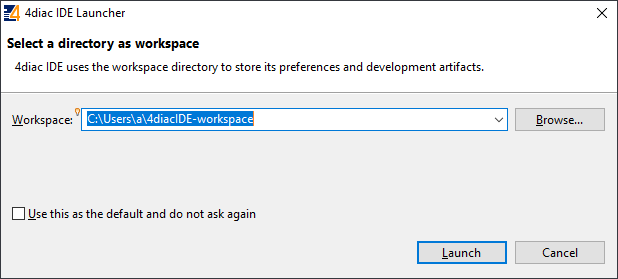](https://wiki.elseta.com/uploads/images/gallery/2020-10/image-1601992159243.png) [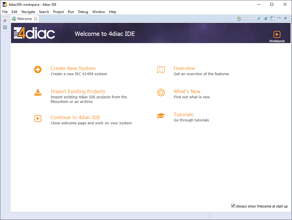](https://wiki.elseta.com/uploads/images/gallery/2020-10/image-1601992177394.png) After that, a user should be met by the welcome window. If such a window is not shown, one can create a project by selecting File -->New --> Project and filling in the required fields. Here is a library of function blocks, which are working with the newest 4Diac version: [Elseta Library.zip](https://wiki.elseta.com/attachments/536). Upload the library to your project folder. To create a simple application, simply drag and drop objects from the palette to the canvas and wire them accordingly. Event trigger and data pathways cannot be connected. Displayed below is an example of a simple blinker application.Having less wiring by connecting several signals to the same subnet as PCB designer (such as Altium Designer) as of 4Diac IDE 1.11.3 is not supported. However, if some parts are used frequently, it is highly advised to have less wiring by simply compiling several elements into a sub-application. For this, you would have to select elements to be grouped, press the right key and select New Sub application. You can later change the names of such elements and their pins.
[](https://wiki.elseta.com/uploads/images/gallery/2020-10/image-1601992239152.png) [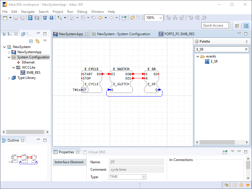](https://wiki.elseta.com/uploads/images/gallery/2020-10/image-1601992245178.png) In the System Configuration section, drag and drop a FORTE\_PC device, and an Ethernet segment and link them. For debugging in the local (PC) runtime, leave the address ”localhost:61499”. For testing on a WCC Lite, enter the IP address of the device, along with the port number (which by default is 61499 as well). [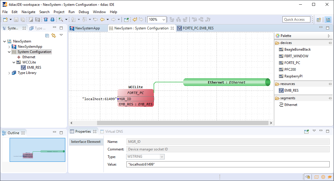](https://wiki.elseta.com/uploads/images/gallery/2020-10/image-1601992273595.png) To deploy the application, the circuit needs to be mapped to the controller. For a non-distributed application (distributed application cases will not be discussed in this chapter), all the FBs of the application need to be selected and mapped to the configured controller as shown: [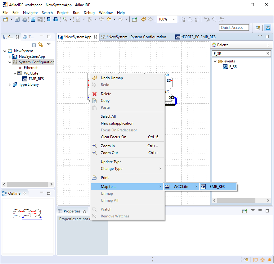](https://wiki.elseta.com/uploads/images/gallery/2020-10/image-1601992299991.png) To start the application execution, an initial trigger needs to be present. For a non-distributed application, the initial event trigger needs to be wired from the START function block in the resource section as shown: [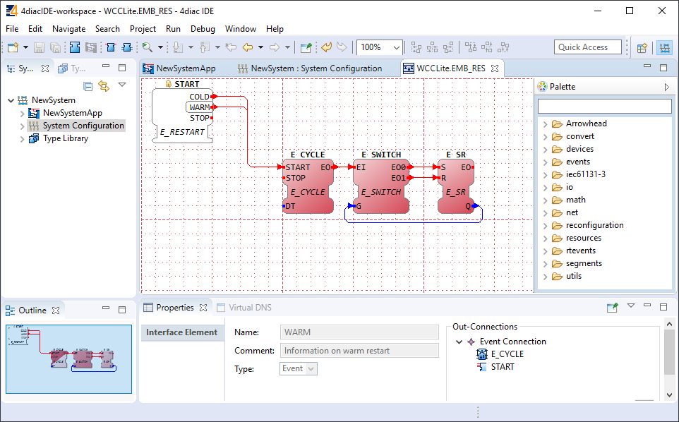](https://wiki.elseta.com/uploads/images/gallery/2020-10/image-1601992323578.png) [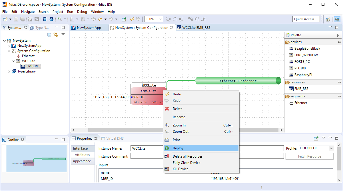](https://wiki.elseta.com/uploads/images/gallery/2020-10/image-1601992330383.png) To deploy the application, go to the System Configuration tab and simply select ”Deploy” from the right-click menu of the controller device. If a running application exists in the runtime, you may be asked whether you want to replace it. This will only overwrite the application in the memory and not the storage. If the controller is restarted, the old application will be loaded from the non-volatile memory of the controller. # 20.4 Configuring data endpoints To use WCC Lite as a programmable logic controller, it needs to be configured in a particular way. The PLC functionality of the WCC Lite only allows for the use of data that has been configured in the Excel configuration spreadsheet. This has been done for security purposes and to preserve transmission medium only for data that is available. Only topics defined in the configuration can post or get data. If a certain data entry exists but has not been linked to a PLC program, all calls from the PLC runtime application to the Redis database will be ignored. Therefore it is highly advised to prepare and upload the Excel configuration before using this signal in the PLC application. Some parameters are mandatory for PLC usage. These parameters are shown in two tables below (one for Devices, and one for Signals tab). Please note that other parameters can be used as well, but are not covered because they aren’t specific to PLC functionality. Table. Mandatory parameters for the Devices tab| Parameter | Type | Description |
| name | string | User-friendly device name |
| device\_alias | string | Device alias to be used in configuration |
| enable | boolean | Enabling/disabling of a device |
| protocol | string | Selection of protocol (IEC 61499) |
| Parameter | Type | Description |
| signal\_name | string | User-friendly signal name |
| device\_alias | string | Device alias from a Devices tab |
| signal\_alias | string | Unique signal name to be used |
| source\_device\_alias | string | device\_alias of a source device |
| source\_signal\_alias | string | signal\_alias of a source signal |
Outputs of variable type ANY cannot be directly wired to inputs of the same type and therefore need to be explicitly typed using transitional function blocks.
No more than 20 tags should be published over 5 seconds, as this may overfill the queue. A ”publish only on change” policy is advised.
Currently, only PUBLISH\_1 and SUBSCRIBE\_1 function blocks are supported.
The functionality of the subscribe function is dependent on the presence of the "F\_STRING\_TO\_" function block, for example (F\_STRING\_TO\_REAL). Likewise, the publish function's proper operation relies on the availability of the "F\_ \_TO\_STRING" FB, for example (F\_REAL\_TO\_STRING).
If every step until now has been successful, the user can now proceed to debug the PLC application. # 20.5 Debugging an IEC 61499 application After a project has been built and bound to an existing Excel configuration, a user would normally want to check if every part is working according to the prior requirements before compiling the finished project and uploading it to production. Both the 4Diac framework and WCC Lite offer tools for flexible debugging. There is a possibility that 4Diac FORTE might not start as a process. It may happen if multiple faults occur and the process has stopped. The process is also programmed to not start if no Excel configuration file is found, therefore a user should make sure that Excel configuration is uploaded and ready for use. Individual function blocks can be set to Watch mode: events can be triggered and values can be forced at inputs or outputs (look into images below). To monitor the function blocks, the application should be deployed and the IDE should be in Online mode (Debug --> Monitor System --> NewSystem). Selecting watch mode: [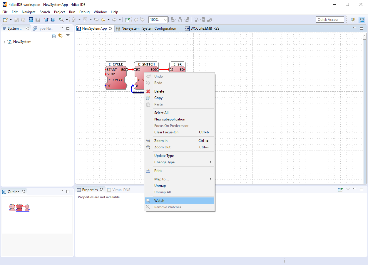](https://wiki.elseta.com/uploads/images/gallery/2020-10/image-1602662191072.png) Function blocks in watch mode: [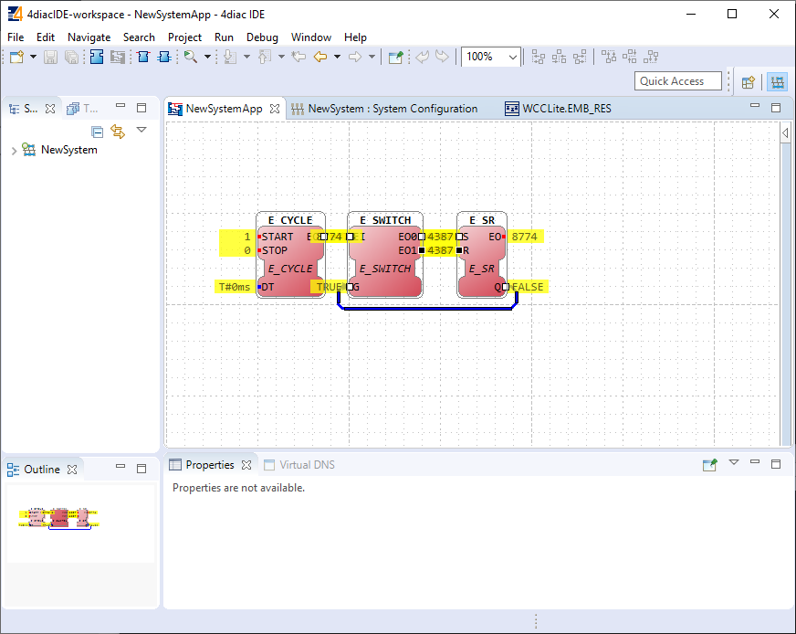](https://wiki.elseta.com/uploads/images/gallery/2020-10/image-1602662206569.png) Seeing information dynamically updated on 4Diac IDE might be very informative, however, some applications might require accessing WCC Lite via a command-line interface. For example, in case of information not being updated one would want to ensure that 4Diac FORTE in WCC Lite is not filtering data out but sending it to the internal database (Redis). To run 4Diac FORTE debug from the command-line interface, a user should write forte and press Enter. All possible choices are shown by adding the -h flag. A debugging example would be: '/etc/init.d/forte stop' to stop any forte processes, 'forte -d7 -r -f /etc/forte/yourfbootfilename.fboot' to launch the debug. More flags are shown in the Table below. Make sure to stop any running process that could use the address that the 4Diac framework is going to use. Table. 4Diac FORTE command line debugging options: ``` -h - Display help informationPlease note that only files with the \*.fboot extension are allowed.
Uploading a file saves it's name and shows it in the web interface. It is advised to carefully choose a filename to separate different versions of PLC application files.
# 20.7 Distributed control application IEC 64199 standard introduced requirements for distributed control. This means that multiple devices can change information between them and make their own decisions based on the data they receive from other sources. This enables distributed applications between multiple WCC Lite devices and all other devices that support IEC 61499. Communication between devices can be configured using: - Publish/Subscribe function blocks (via UDP packets); - Client/Server function blocks (via TCP packets). A Publish block can publish data messages using UDP multi-cast addresses meaning that multiple devices would be able to simultaneously get the same data. However, one would have to make sure that all of the devices support the multi-cast option. This user manual will only cover setting up point-to-point communication between devices via Publish/Subscribe blocks. For more information on communication between several IEC 61499 devices please check the documentation for [Eclipse 4diac framework](https://wiki.elseta.com/link/851#bkmrk-page-title). Let’s say we would like to count how many times the light has been turned on. For this, we can add counting functionality to the application shown in the picture below. The application should run on 2 devices. The blinking part of the application will run on a 4diac FORTE and the count on another 4diac FORTE, see the architecture below. The two different programs running on two separate WCC Lite devices emulate two PLCs. Two different devices can be identified by different colours of function blocks. One can identify the device and its properties by accessing the System Configuration screen as seen below. Yellow function blocks belong to the WCC\_212 device which can be accessed through 192.168.4.212 (port number 61499) whereas brown function blocks belong to the WCC\_218 device which can accessed through 192.168.4.218 (port number 61499). Example blinking application as a distributed system:[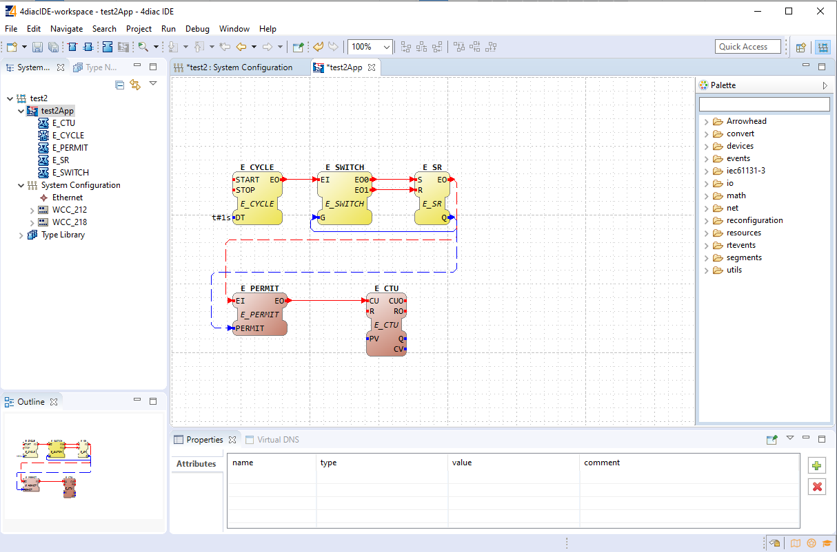](https://wiki.elseta.com/uploads/images/gallery/2020-10/image-1602662769321.png) Example system configuration for a distributed system:[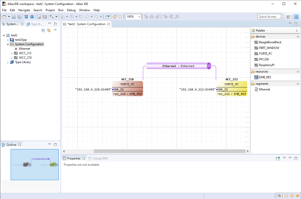](https://wiki.elseta.com/uploads/images/gallery/2020-10/image-1602662862391.png) Example app for blinking part of a distributed system:[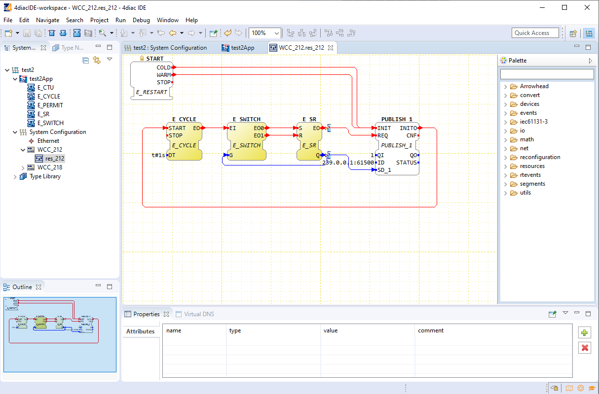](https://wiki.elseta.com/uploads/images/gallery/2020-10/image-1602662875556.png) Example app for counting part of a distributed system:[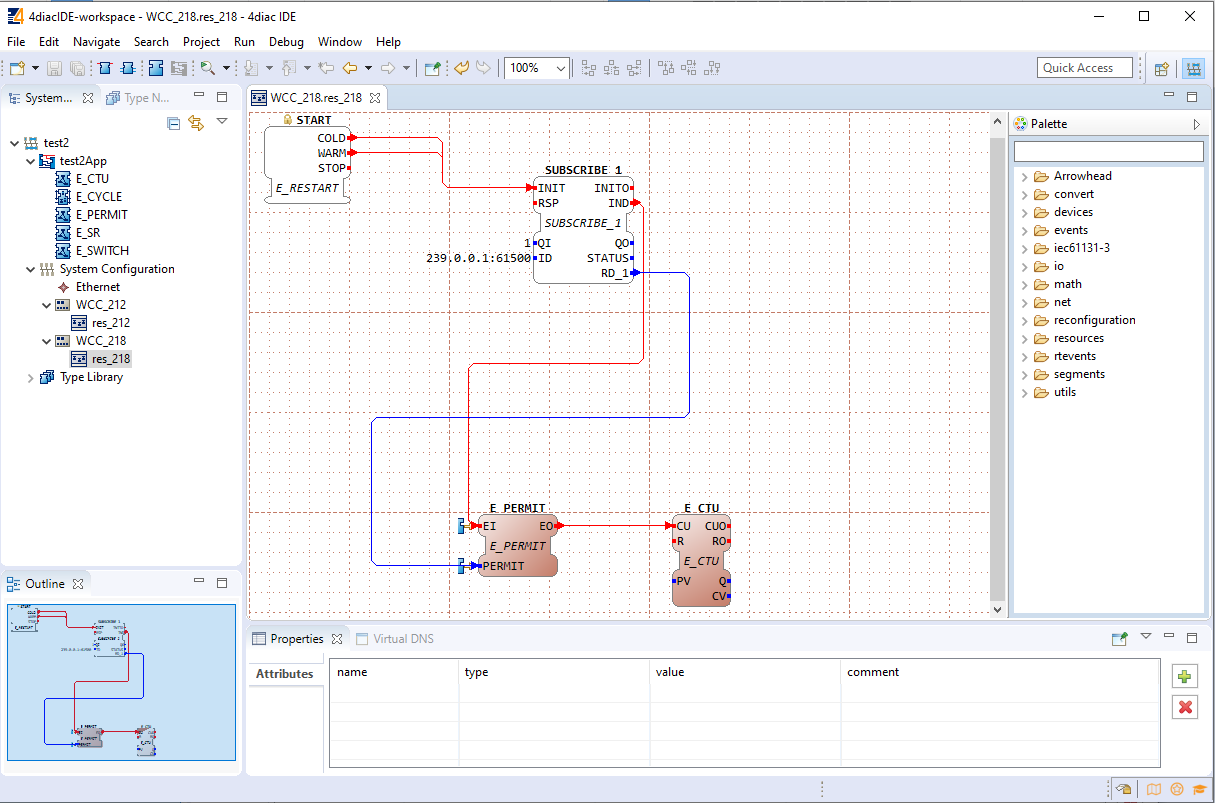](https://wiki.elseta.com/uploads/images/gallery/2020-10/image-1602662888137.png) To count the blinking, two new Function Blocks (FBs) have been added to the existing application for a different device (WCC\_218): - E\_PERMIT - E\_CTU To communicate between devices, an additional PUBLISH\_X/SUBSCRIBE\_X pair must be used. As one can identify, these blocks are not seen when looking at a whole distributed system and should be seen as an intermediary between devices. The PUBLISH\_X FB is used to send messages over the network which are received by an SUBSCRIBE\_X FB. Every time a REQ is triggered, a message is sent according to the ID input. With the value of the ID input, you can specify what specific network protocol you would like to use (e.g., MQTT). If you don’t specify a dedicated protocol the default as defined in the ”IEC 61499 Compliance Profile for Feasibility Demonstrations” is used. The number X in PUBLISH\_X is the number of data elements that you want to send in the message. Since we are only sending one value we used PUBLISH\_1. The used ID value specifies an IP: PORT pair. # 21 Lua script runner ### Introduction Lua is a powerful, efficient, lightweight scripting language. It has been used in many industrial applications with an emphasis on embedded systems. Lua has a deserved reputation for performance. To claim to be "as fast as Lua" is an aspiration of other scripting languages. Several benchmarks show Lua as the fastest language in the realm of interpreted scripting languages. Lua is fast not only in fine-tuned benchmark programs but in real life too. Substantial fractions of large applications have been written in Lua. In the WCC Lite system, Lua is used for extending the functionality of Excel configuration adding an interface to the existing signal-linking engine. Provided functions enable to recreate of PLC functionality and modify any value with ease. ### Overview ##### Execution types: Lua runner provides 3 execution modes: interval, date, and signal, which can be specified in [**execution\_type**](https://wiki.elseta.com/link/915#bkmrk-parameter-descriptio-0). **Interval**: executes provided script based on provided time interval in [**execution\_parameter**](https://wiki.elseta.com/link/915#bkmrk-parameter-descriptio-0). It uses milliseconds, meaning if a 500 value is provided, then the script is executed every 500 milliseconds. **Date:** schedules a script execution based on the provided cron expression in [**execution\_parameter**](https://wiki.elseta.com/link/915#bkmrk-parameter-descriptio-0). The format consists of 6-7 fields separated by space.| Name | Required | Allowed Values | Allowed Special Characters |
|---|---|---|---|
| Seconds | Y | 0-59 | , - \* / |
| Minutes | Y | 0-59 | , - \* / |
| Hours | Y | 0-23 | , - \* / |
| Day of month | Y | 1-31 | , - \* / |
| Month | Y | 0-11 or JAN-DEC | , - \* / |
| Day of week | Y | 1-7 or SUN-SAT | , - \* / |
| Year | N | empty or 1970-2099 | , - \* / |
These functions are equivalent to REDIS functions.
Function **save** saves the specified value to flash memory for use after reboot. The same value sub-values apply to execution. ```Lua save(signals.tag1, 50) -- this will save a value to tag1These functions will require significant CPU resources even if the message log level is higher than default and no message is printed.
##### Web interface The web interface is used to see what scripts are running and, if there is a script provided, to stop/start a script. After configuring a device with Lua runner as protocol, the script runner protocol hub tab will be populated with devices that were configured: [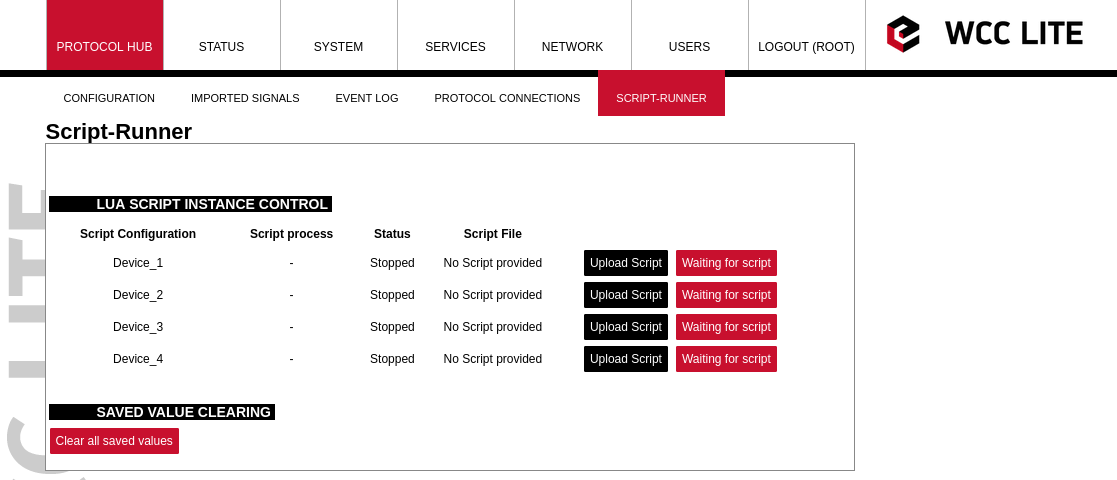](https://wiki.elseta.com/uploads/images/gallery/2022-10/image-1665406373895.png) Then by pressing the Upload Script button, a script will be available to be selected (the name of the script will be changed to match device\_alias). When uploaded the script will not be started automatically, pressing start will be necessary. [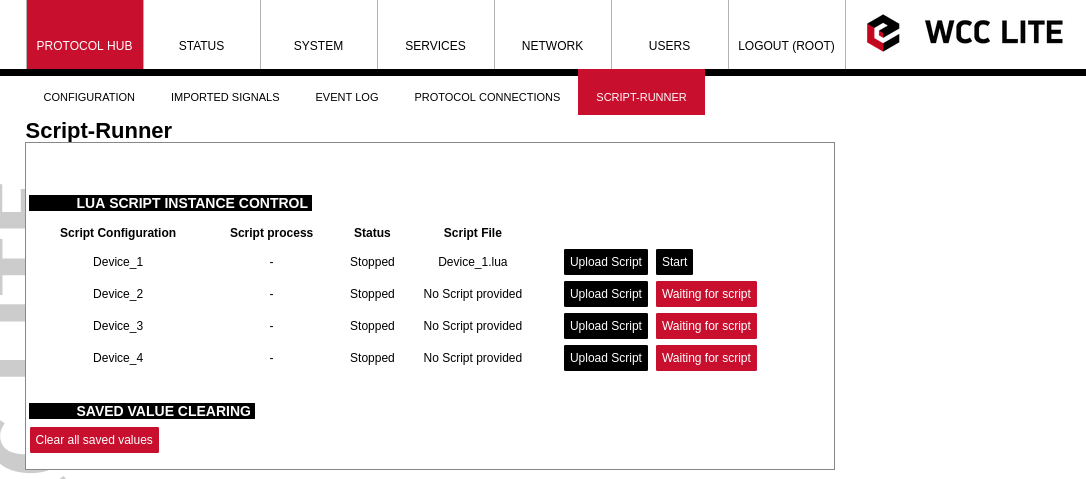](https://wiki.elseta.com/uploads/images/gallery/2022-10/image-1665408922682.png) After pressing start, the script will be started, if there are errors it will try to start, but after a few attempts, it will stop. [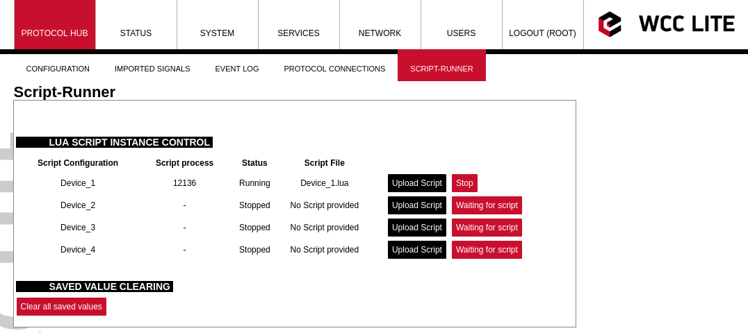](https://wiki.elseta.com/uploads/images/gallery/2022-10/image-1665409121771.png) The clear all saved values button is used to clear the memory of saved values. Having a lot of values saved is not healthy for the SD card and faults can happen. Also, the script runner process initialization is slowed down when a lot of saved values are used. ### Configuration #### Device configuration parameters:| **Parameter** | **Type** | **Description** | **Required | **Default value** (when not specified) | **Range** | |
| Min | Max | |||||
| name | string | User-friendly name for a device | Yes | |||
| device\_alias | string | Alphanumeric string to identify a device | Yes | |||
| description | string | Description of a device | No | |||
| enable | boolean | Enabling/disabling of a device | No | 1 | 0 | 1 |
| protocol | string | Protocol to be used | Yes | lua runner | ||
| execution\_type | string | Execution type to be used | Yes | interval, date, signal | ||
| execution\_parameter | int, string | Parameters for execution | Yes | NULL | interval time in ms, date in cron format, additional signal | |
| queue\_max | int | Maximum execution queue jobs | No | 3 | 0 to disable the queue | |
| error\_limit | int | Error limit before stopping | No | 3 | 0 to disable | |
| keep\_alive\_time\_ms | int | Time to keep the script alive in milliseconds | No | 600000 | 0 to disable | |
| **Parameter** | **Type** | **Description** | **Required | **Default value** (when not specified) | **Range** | |
| Min | Max | |||||
| signal\_name | string | User-friendly name for a signal | Yes | |||
| device\_alias | string | Alphanumeric string to identify a device | Yes | Must match device\_alias in the device sheet | ||
| signal\_alias | string | Unique alphanumeric name of the signal to be Yes used | Yes | |||
| iterator | string | Lua table name to which signal is added | No | signals | ||
| default\_value | string | Default value for a signal | No | |||
| execute | int | Enable signal update trigger to execute script (only available for signal execution mode) | No | 0 | 0 | 1 |
WCC Lite supports MQTT messaging compatible with MQTT v3.1 standard (starting from version **v1.4.0**). Such messaging is possible via mapping of Redis and MQTT data therefore data can be transmitted from any protocol that is supported by WCC Lite.
All standard functions, except for data encryption, are supported. Encrypted messages are not supported yet, therefore to ensure security a user would have to use a VPN service. A user can choose from three different Quality of Service levels, select if messages are to be retained, authenticate users and optionally send Last Will messages. To configure WCC Lite a user can fill in the needed parameters in Excel configuration. These parameters are shown in the two tables below. Table. MQTT parameters for the Devices tab| **Parameter | **Type | **Description | **Required | **Default value** (when not specified) | **Range** | |
| Min | Max | |||||
| name | string | User-friendly device name | Yes | |||
| device\_alias | string | Device alias to be used in the configuration | Yes | |||
| enable | boolean | Enabling/disabling of a device | No | 0 | 0 | 1 |
| protocol | string | Selection of protocol | Yes | MQTT | ||
| host | string | MQTT broker IP address/Domain name selection | Yes | |||
| port | integer | MQTT broker port selection | No | 1883 | ||
| gi\_interval\_ms | integer | Parameter to determine how frequently should all values be sent at once. Disabled if equal to 0. | No | 0 | ||
| enable\_threshold | boolean | A parameter to determine if identical values should not be sent multiple times in a row. | No | 1 | 0 | 1 |
| mqtt\_qos | integer | MQTT Quality of Service for the message as in standard | No | 0 | 0 | 2 |
| mqtt\_retain | boolean | Selecting if the MQTT broker should retain the last received messages | No | 0 | 0 | 1 |
| username | string | MQTT user name | Yes | |||
| password | string | MQTT user password | Yes | |||
| auth | string | Selecting if TLS should be used | Yes | none, password, tls | ||
| ca\_certificate | string | Certificate authority file for TLS connection | Yes (If auth = tls) | |||
| client\_certificate | string | Client certificate file for TLS connection | Yes (If auth = tls) | |||
| client\_key | string | The private key that corresponds to the client certificate for TLS connection | Yes (If auth = tls) | |||
| use\_last\_will | boolean | Selecting if MQTT should use the Last Will and Testament functionality (Default: False) | No | 0 | 0 | 1 |
| last\_will\_topic | string | Topic to which an MQTT message would be sent if the device abruptly disconnected the message broker | Yes (If use\_last\_will = True) | |||
| last\_will\_message | string | Message to be sent over MQTT if the device abruptly disconnected message broker | No | |||
| last\_will\_qos | integer | MQTT Quality of Service selection as in standard | No | 0 | 0 | 2 |
| last\_will\_retain | boolean | Selecting if the MQTT broker should retain the last will message | No | 0 | 0 | 1 |
| client\_id | string | User-friendly name for client ID | No | |||
| **Parameter | **Type | **Description | **Required | **Default value** (when not specified) | **Range** | |
| Min | Max | |||||
| signal\_name | string | User-friendly signal name | Yes | |||
| device\_alias | string | Device alias from a Devices tab | Yes | |||
| signal\_alias | string | Unique signal name to be used | Yes | |||
| source\_device\_alias | string | device\_alias of a source device | Yes | |||
| source\_signal\_alias | string | signal\_alias of a source signal | Yes | |||
| enable | boolean | Enabling/disabling of an individual signal | No | 1 | 0 | 1 |
| log | integer | Allow signal to be logged. Log signal with 1 and no logging with 0. | No | 0 | ||
| topic | string | Topic name to override the value built by default | No | |||
| periodic\_update\_ms | integer | Signal value is published periodically according to the value set. | No | - | - | - |
If the MQTT Client does not work properly (e.g. no communication between devices, data is corrupted, etc.), a user can launch a debug session from the command line interface and find out why the link is not functioning properly.
To launch a debugging session, a user should stop `mqtt-client` process and run `mqtt-client` command with respective flags as was shown above.
# 23 Data Export ## General Various protocols are made to transmit data points as they are generated. This is enough for a lot of systems (e.g. SCADA) that have their databases and devices only have to buffer fairly recent messages in case of connection or transmission errors. However, there is frequently a need to save and keep the data in files, grouped in batches, and later transmit these batches to a remote server via HTTP(S) or FTP(S). For this purpose, a dedicated protocol has been created and called **Data export.**Data export functionality is available since firmware version v1.5.0, of WCC Lite.
## Overview Data export service gathers information from other protocols and puts it into files (optionally compressing them) after a timeout or when data buffers fill up; eventually periodically sending them to a server. HTTP(S) and FTP(S) servers with optional authentication are supported. A user can optionally choose between ISO8601 and UNIX timestamp time formats (the latter being the default value). More than one instance can be set up, for instance, some of the information can be sent to an FTP server, while others could be transmitted to the HTTP server which can handle POST requests. ## Using WCC Lite for data export To configure WCC Lite to use a data export server a user can fill in the needed parameters in Excel configuration. These parameters are shown in the two tables below. Default values are shown in bold font. *Data export (data-export) parameters for Devices tab table:*| **Parameter** | **Type** | **Description** | **Required | **Default value** (when not specified) | **Range** | |
| Min | Max | |||||
| name | string | User-friendly device name | Yes | |||
| device\_alias | string | Device alias to be used in configuration | Yes | |||
| enable | boolean | Enabling/disabling of a device | No | 1 | 0 | 1 |
| protocol | string | Selection of protocol | Yes | Data Export | ||
| timeout | integer | The time frame during which transmission to the remote server has to be completed (**in seconds**) | No | 5 | ||
| type | string | Selection of file format | No | csv-simple | cvs-periodic csv-simple, json-simple, json-samples | |
| host | string | A URL of the remote server where files should be sent | Yes | |||
| upload\_rate\_sec | integer | Frequency of generated file uploads (**in seconds)** | No | 60 | ||
| records\_buffer\_size | integer | A maximum amount of data change entries to hold before initiating the logging mechanism | No | 100 | ||
| logging\_period\_sec | integer | Describe how frequently the data buffer of records\_buffer\_size is saved to the file | No | 10 | 1 | 3600 |
| log\_folder | string | A folder in the WCC Lite file system to save generated files (**”/var/cache/data-export”**) | No | |||
| timestamp | string | Selection of time format | No | unixtimestamp | unixtimestamp, iso8601 | |
| compress | string | Selection of file compression mechanism | No | none | none, gz, tar.gz | |
| compress\_password | string | Enable the feature of file password protection | No | yes, true | ||
| csv\_field\_separator | string | Columns separator in .csv file format | No | "," - (comma) | "," - (comma) ";" - (semicolon) "." - (dot) " " - whitespace) "|" - (pipe) | |
| csv\_decimal\_separator | string | Decimal separator in values | No | "." - (dot) | "." - (dot) "," - (comma) | |
The same symbols cannot be selected for both csv\_field\_separator and csv\_decimal\_separator. In such case both of them will be set to default values ”.” and ”,” respectively.
The data generation rate may be bigger than what the data buffer can hold (controlled by *records\_buffer\_size* and *logging\_period\_sec*). To make sure that no data loss occurs there’s an additional data logging call made in case the data buffer reaches a *records\_buffer\_size* value. Signals to be sent are configured differently than signals for most other protocols. As data export service only transmits signals and does no data processing, usual signal logic is not used for them. That means that: • Signals for data export service are not seen in the *Imported Signals* tab; • Signals for data export service are configured in a different Excel sheet called DataExport The parameters to be filled in the DataExport sheet are shown in the table below. *Data export (data-export) parameters for the DataExport tab*| **Parameter** | **Type** | **Description** | **Required | **Default value** (when not specified) | **Range** | |
| Min | Max | |||||
| device\_alias | string | Device alias to be used in configuration Yes | Yes | |||
| device\_name | string | User-friendly device name as in the Device sheet | Yes | |||
| tag\_name | string | User-friendly signal name | Yes | |||
| source\_device\_alias | string | device\_alias of a source device | Yes | |||
| source\_signal\_alias | string | source\_alias of a source signal | Yes | |||
| enable | boolean | Enabling/disabling of a measurement to be transmitted and logged | No | 1 | 0 | 1 |
| attribute | string | An additional attribute to be attached to a signal | No | |||
The below-described parameters for debugging are accessible over the console (SSH).
`-h [--help] Display help information` `-c [--config] Configuration file location` `-V [ –version ] Show version` `-dIt should be noted that assigning a user to a root group only gives complete authority over the web interface. Permissions for a command line interface should be given by a root user via command line interface.
The following commands may be used in the command line interface for user control: **adduser** - create a new user or update default new user information When invoked without the **-D** option, the *adduser* command creates a new user account using the values specified on the command line plus the default values from the system. Depending on command line options, the useradd command will update system files and may also create the new user’s home directory and copy initial files. **passwd** - change user password The *passwd* command changes passwords for user accounts. A normal user may only change the password for his/her account, while the superuser may change the password for any account. *passwd* also changes the account or associated password validity period. **deluser** - delete a user account and related files The *deluser* command modifies the system account files, deleting all entries that refer to the user name LOGIN. The named user must exist.If a user intends to use a newly created user account via both the commandline interface and web interface he should create and delete users via the web interface and not use adduser and deluser commands as they don’t create uci entries.
For more information about controlling users via the command line interface, one should refer to Linux documentation. #### Authentication via external service WCC Lite supports external authentication via the RADIUS service. Remote Authentication DialIn User Service (RADIUS) is a networking protocol that provides centralized Authentication, Authorization, and Accounting (AAA or Triple A) management for users who connect and use a network service. RADIUS is a client/server protocol that runs in the application layer and can use either TCP or UDP as transport. Network access servers, the gateways that control access to a network, usually contain a RADIUS client component that communicates with the RADIUS server. RADIUS is often the backend of choice for 802.1X authentication as well. The RADIUS server is usually a background process running on a UNIX or Microsoft Windows server. In WCC Lite RADIUS Client is implemented since WCC Lite software version v1.2.4. The user sends a request to a WCC Lite to gain access to access using access credentials posted in an HTTP/HTTPS WCCLite web login form This request includes access credentials, typically in the form of a username and password. Additionally, the request may contain other information that the Device knows about the user, such as its network address or information regarding the user’s physical point of attachment to the device. The RADIUS server checks that the information is correct using authentication schemes such as PAP, CHAP or EAP. The user’s proof of identification is verified, along with, optionally, other information related to the request, such as the user’s network address, account status, and specific network service access privileges. Historically, RADIUS servers checked the user’s information against a locally stored flat file database. Modern RADIUS servers can do this or can refer to external sources—commonly SQL, Kerberos, LDAP, or Active Directory servers—to verify the user’s credentials. The RADIUS server then returns one of two responses to the WCC Lite: 1. **Access-Reject** - The user is unconditionally denied access to all requested resources. Reasons may include failure to provide proof of identification or an unknown or inactive user account. 2. **Access-Accept** - The user is granted access. Once the user is authenticated, the RADIUS server will periodically check if the user is authorized to use the service requested. A given user may be allowed to get admin rights or user rights depending on permissions set on the RADIUS Server. Again, this information may be stored locally on the RADIUS server or may be looked up in an external source such as LDAP or Active Directory. To use this mechanism a RADIUS server must be configured. The parameter Radius Authentication must be Enabled on WCC Lite. As of firmware version 1.2.13, the RADIUS service is disabled by default. The service can be enabled at System -->Startup. If the RADIUS authentication is enabled, WCC Lite uses the RADIUS server IP address and the RADIUS shared secret key for communication with the External RADIUS Server. After entering the login credentials and login attempt, WCC Lite sends these credentials to the RADIUS server for authentication. If the RADIUS server is available, it compares the login credentials: - If the comparison is successful, the RADIUS server returns the specific user role and Access-Accept; - If the login credentials are invalid, the Radius Server returns Access-Reject and the logon fails. - If the RADIUS server is not available and the fallback option is disabled login into WCC Lite will be impossible. If the RADIUS server is not available and timeout occurs, login will be attempted via local login credentials. *Enabled:* Enables or disables this server. *Hostname/IP:* Hostname or IP address of RADIUS server. *Timeout:* Timeout in seconds to wait for server response. *Shared* secret: Key shared between RADIUS server and RADIUS client. *Add:* Adds auxiliary (backup) server. #### Audit Log WCC Lite OS with version >1.2.0 has integrated Audit logging for important events such as: - Login/logout. - Wrong password attempts to log into the system. - Device boot event, when the system was started. - Device reboot/halt event. - Configuration changes. - Firmware changes. - Date and time changes in the system (excluding automatic system time updates over NTP or IEC 60870510x protocol)Enabling external system log server setup in System properties --> Logging is recommended. The system stores logs in RAM by default due to limited flash storage. Rebooting or powering off the device will result in a loss of log history.
#### Secure your device’s access There are some possibilities to grant access to the device (or to any PC/Server): 1. ask for nothing: anybody who can establish a connection gets access 2. ask for a username and password on an unsecured connection (e.g. telnet) 3. ask for a username and password on an encrypted connection (e.g. SSH) (e.g. by following firstlogin) 4. ask for a username and merely a signature instead of a password (e.g. SSH with signature.authentication) If you ask for a username/password, an attacker has to guess the combination. If you use an unencrypted connection, he could eavesdrop on you and obtain them. If you use an encrypted connection, any eavesdropper would have to decrypt the packets first. This is always possible. How long it takes to decrypt the content, depends on the algorithm and key length you used. Also, as long as an attacker has network access to the console, he can always run a bruteforce attack to find out the username and password. He does not have to do that himself: he can let his computer(s) do the guessing. To render this option improbable or even impossible you can: - not offer access from the Internet at all, or restrict it to certain IP addresses or IP address ranges - by letting the SSH server dropbear and the webServer lighttpd not listen on theexternal/WAN port - by blocking incoming connections to those ports (TCP 22, 80 and 443 by default) in yourfirewall - make it more difficult to guess: - don’t use the username root - don’t use a weak password with 8 or less characters - don’t let the SSH server dropbear listen on the default port (22) - use the combination of: - username different than the root - Tell Dropbear to listen on a random port (should be >1024): **System --> Administration -->Dropbear Instance --> Port** - public key authentication. Your public keys can be specified in **Administration --> System > SSHkeys**. An older guide to DropBear SSH public key authentication has detailed information on generating SSH keypairs which include the public key(s) you should upload to your configuration. ### Groups rights If the user is logged on via an external server, its authentication level is acquired. As no direct mapping to existing users is used, authentication levels are a way to grant proper permissions for external users. WCC Lite uses a CISCO authentication system, meaning that there are fifteen different permission set level settings, of which the first 14 can be configured to enable or disable View and Edit permissions. #### SSH Access SSH Access of WCC Lite is made by the Dropbear software package. To extend the basic functionality, the Pluggable Authentification Module (PAM) for RADIUS is used. This enables users to add their authentification modules as long as they are properly configured. Fifteen levels of authorization are mapped for SSH access, meaning that the user should be able to access SSH with credentials used to log into the web interface. However, one should note that permissions in the command line interface are not configurable via the web interface. This means that the first fourteen levels are restricted to basic permissions made by creating a group by default. Highest level user has all the permissions the root user has. If a user intends to change permissions for user groups, it should be done via command line interfaces. It is only advised for advanced users. #### Web interface permissions Fifteen levels of authorization permission are mapped for web interface access, meaning that the user should be able to access the web interface with credentials used to log into the command line interface. Users assigned to the highest authorization level group can access every possible screen therefore this groups cannot be edited. The figure below shows a screen containing already existing groups in a device. Pressing *Add New Group...* guides the user to an *Edit group* screen, with *Edit* and *Delete* buttons respectively user can Edit and Delete the configuration of a given user group. [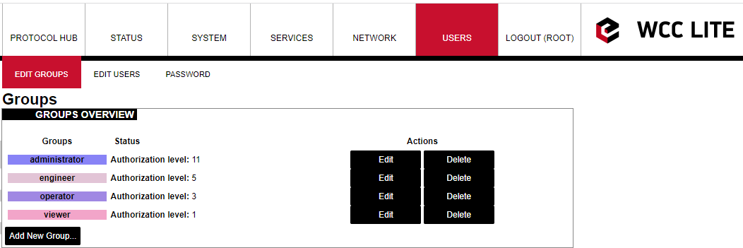](https://wiki.elseta.com/uploads/images/gallery/2023-07/image-1689335982520.png) Screen showing existing user groups[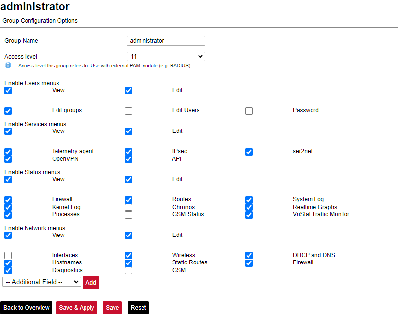](https://wiki.elseta.com/uploads/images/gallery/2023-07/image-1689336022397.png) Screen for user group editing Edit group screen for an individual group can be seen in Figure above. Group name doesn’t have any specific purpose for RADIUS, but it enables naming groups with words most meaningful for a given context. Access level values can only be integers between 1 and 14, other values will result in an error message only unconfigured levels are shown in a dropdown list when configuring. Other fields are dedicated to an individual menu configuration. To add more first-level menus user should select from a dropdown list at the bottom named *–Additional Field–* and press Add. Permissions for the web interface are split into two parts: *View* and *Edit.* *View* permissions can be assigned to second-level menus meaning that only allowed subtabs are shown for a user. Selecting the *View* checkbox shows more parameters containing all the subtabs (submenus). If a user can access a given screen, it means all of the actions in that screen are available to be executed. Therefore, if a user with a lot of restrictions shouldn’t, for example, import Excel configuration to WCC Lite, a tab containing this action (*Protocol Hub>Configuration*) should be disabled in his groups' configuration. *Edit* permissions can be assigned to first-level menus meaning that if this permission is given, every configuration in the first-level menu can be saved and applied successfully ### Conformance to IEC 62351 standard IEC 62351 is a standard developed by WG15 of IEC TC57. This is developed for handling the security of TC 57 series of protocols including IEC 608705 series, IEC 608706 series, IEC 61850 series, IEC 61970 series and IEC 61968 series. The different security objectives include authentication of data transfer through digital signatures, ensuring only authenticated access, prevention of eavesdropping, prevention of playback and spoofing, and intrusion detection. Conformance to the IEC 62351 standard of WCC Lite devices is described in the table below. Conformance to IEC 62351 standard| **Standard** | **Description** | **Topic** | **Implemented** | **Version** |
| IEC 62351-3 | Security for any profiles including TCP/IP | TLS Encryption | Yes | >=1.3 |
| Node Authentication using X.509 certificates | Yes | >=1.3 | ||
| Message Authentication | Yes | >=1.3 | ||
| IEC 62351-4 | Security for any profiles including MMS | Authentication for MMS | Yes | >=1.5 |
| TLS (RFC 2246)is inserted between RFC 1006 & RFC 793 to provide a transport layer security | Yes | >=1.5 | ||
| IEC 62351-5 | Security for any profiles including IEC 608705 | TLS for TCP/IP profiles and encryption for serial profiles | No | |
| IEC 62351-6 | Security for IEC 61850 profiles | VLAN use is made mandatory for GOOSE | No | |
| RFC 2030 to be used for SNTP | No | |||
| IEC 62351-7 | Security through network and system management | Defines Management Information Bases (MIBs) that are specific for the power industry, to handle network and system management through SNMP-based methods | No | |
| IEC 62351-8 | Role-based access control | Covers the access control of users and automated agents to data objects in power systems using rolebased access control (RBAC) | Yes | >=1.2.6 |
| IEC 62351-9 | Key Management | Describes the correct and safe usage of safety-critical parameters, e.g. passwords, encryption keys. | No | |
| Covers the whole life cycle of cryptographic information (enrolment, creation, distribution, installation, usage, storage and removal) | No | |||
| Methods for algorithms using asymmetric cryptography | No | |||
| A secure distribution mechanism based on GDOI and the IKEv2 protocol is presented for the usage of symmetric keys, e.g. session keys | No | |||
| IEC 62351-10 | Security Architecture | Explanation of security architectures for the entire IT infrastructure | No | |
| Identifying critical points of the communication architecture, e.g. substation control centre, substation automation | No | |||
| Appropriate mechanisms security requirements, e.g. data encryption, user authentication | No | |||
| Applicability of wellproven standards from the IT domain, e.g. VPN tunnel, secure FTP, HTTPS | No | |||
| IEC 62351-11 | Security for XML Files | Embedding of the original XML content into an XML container | No | |
| Date of issue and access control for XML data | No | |||
| X.509 signature for authenticity of XML data | No | |||
| Optional data encryption | No |
| **Parameter** | **Type** | **Description** | **Required** | **Default Value** (when not specified) | **Range** | |
| Min | Max | |||||
| name | string | User-friendly name for a device | Yes | |||
| description | sting | Description of a device | No | |||
| device\_alias | string | Alphanumeric string to identify a device | Yes | |||
| enable | boolean | Enabling/disabling of a device | No | 1 | 0 | 1 |
| protocol | string | Protocol to be used | Yes | sms receiver | ||
| host | string | Telephone number from which to receive SMS | Yes | \[all, +37061111111\] (case-sensitive, separated by command or space) | ||
| **Parameter** | **Type** | **Description** | **Required** | **Default Value** (when not specified) | **Range** | |
| Min | Max | |||||
| signal\_name | string | User-friendly signal name | Yes | |||
| device\_alias | string | Alphanumeric string to identify a device | Yes | |||
| signal\_alias | string | Unique alphanumeric name of the signal to be Yes used | Yes | |||
| enable | boolean | Enabling/disabling of an individual signal | No | 1 | 0 | 1 |
| job\_todo | string | Choose command type | Yes | \[SIGNAL, SYSTEM\] (case-insensitive) | ||
| tag\_job\_todo | string | which command to execute (if signal, then configure the SMS) | \[REBOOT WCC, REBOOT MODEM, SWITCH SIM, SHOW IP, SET RAT <CUSTOM>%F\] (case-insensitive) | |||