8 Internal web page
WCC Lite is configured via an internal web browser, so no additional software is required.
- 8.1 Initial Setup
- 8.2 Site layout
- 8.3 Protocol Hub
- 8.4 Status
- 8.5 System
- 8.6 Services
- 8.7 Network
- 8.8 Users
- 8.9 Logout
8.1 Initial Setup
WCC Lite comes with a static network configuration with its IP set to 192.168.1.1. For initial setup set a static IP address on your computer and connect your network card to the WCC Lite with an ethernet cable.
8.1.1 Static IP Address Setup on Windows
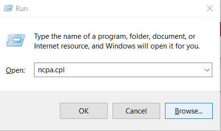
1. Press Win+R on your keyboard. This will open the run window. Enter ncpa.cpl and press OK. This will open the Network Connections window.
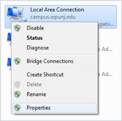
2. Right-click on the Local Area Connection icon, then select Properties
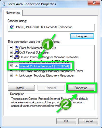
3. In the window that opens, click on Internet Protocol Version 4 (TCP/IPv4) (you may need to
scroll down to find it). Next, click on the Properties button.
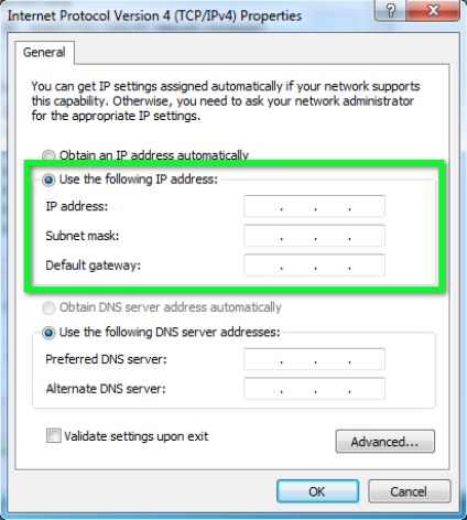
4. In the window that opens, click the Use the following IP address radio button. Fill in the following fields and click OK:
- IP address: 192.168.1.2
- Subnet mask: 255.255.255.0
- Default gateway: (leave empty)
8.1.2 Connecting to an internal web page
If your computer IP address is set up and an ethernet cable is connected, power up the device. Wait a few minutes until the device boots. Then open your web browser and enter the following URL: http://192.168.1.1/
Supported web browsers:
- Google Chrome (recommended)
- Mozilla Firefox
- Internet Explorer 8 or later
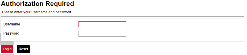
Login with the root user:
- Username: root
- Password: wcclite
It is recommended to change the password immediately to avoid any unauthorized access.
Before plugging WCC Lite with a static IP address into the local computer network, make sure to check if such an address is not already reserved by other devices.
8.2 Site layout

It provides the main navigation through the website. Contains the following sections:
- PROTOCOL HUB: configuration related to data exchange between WCC Lite and other devices.
- STATUS: system information and diagnostics.
- SYSTEM: basic system settings such as time setup.
- SERVICES: various other services.
- NETWORK: network-related settings and services.
- USERS: existing user groups and management of their permissions
- LOGOUT: user logout.
8.3 Protocol Hub
The Protocol HUB section stores the configuration for every connected device. You can configure it by importing settings from an Excel file.
Avoid editing Excel configuration files via Google Docs or pasting values from unknown sources (especially websites or PDFs). That's because it may cause some errors related to formating of data.
Configuration
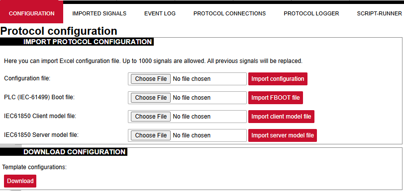
In this tab, a user can:
- Import new configuration from Excel file (.xls, .xlsx formats). If any errors in the file are found, the device will not be imported, and the importing process will be stopped.
- Import .fboot file for PLC.
- Import the IEC61850 Server model file
- Import the IEC61850 Client model file
- Download the current configuration Excel file.
- Download a template configuration Excel file.
Imported Signals
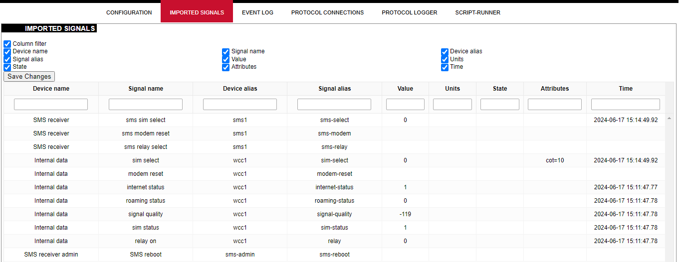
The imported signals section shows basic information about the applied configuration. This section is used for viewing only. Column filter allows the signals to be filtered according to the information needed.
Event Log
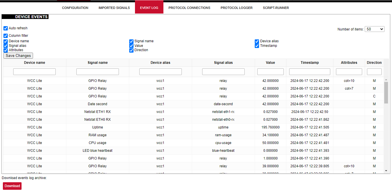
Event Log is the timestamped status data. It allows reviewing the latest events and changes for devices' state changes in chronological order. The newest events are shown at the top of the list. WCC Lite will timestamp the status data with a time resolution of one millisecond. Column filter allows filtering of the data according to the information needed.
Initially, all breakers, protection contacts digital status input points in the WCCLite; events captured from IEDs (Intelligent electronic devices) shall be configured as Event Log points. It’s possible to assign any digital status input data point in the WCCLite as an SOE point with an Excel template during configuration.
Each time a device changes state, the WCClite will save it with timetag in internal storage. Event Log can also be downloaded by pressing the download button at the bottom of the page.
Events are recorded only for devices with the log field set to 1.
Protocol Connections
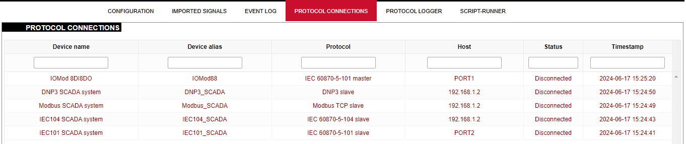
The protocol connections section shows configured devices and their respective ports, and statuses.
Protocol Logger
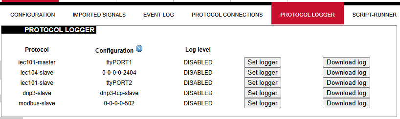
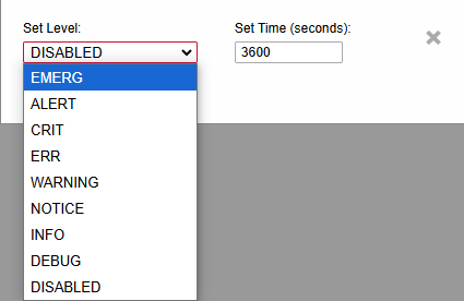
Protocol logger allows users to set a certain debug level for any protocol. The debug log can then be downloaded as a file by clicking the Download log button. To set the logger, click on the Set logger button and select the debug level and time in which the logger will be active. Debug levels can be seen in the picture below.
8.4 Status
Overview
System
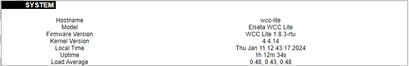
The system section in the status tab shows basic information about the system's current status.
Hostname: The label that is used to identify the device in the network.
Model: Model of the device.
Firmware version: Current firmware version.
Kernel version: Current kernel version.
Local Time: Current local time.
Uptime: The time a device has been working.
Load average: Measure CPU utilization of the last 1, 5, and 15-minute periods. A load of 0.5 means the CPU has been utilized 50% over the previous period. Values over 1.0 mean the system was overloaded.
Memory

The ”Memory” window provides information on memory usage on the device.
Total available memory: The amount of available memory that could be used over installed physical memory.
Free: The amount of physical memory that is not currently used over installed physical memory.
Buffered: The amount of buffered memory currently used for active I/O operations over installed physical memory.
Network
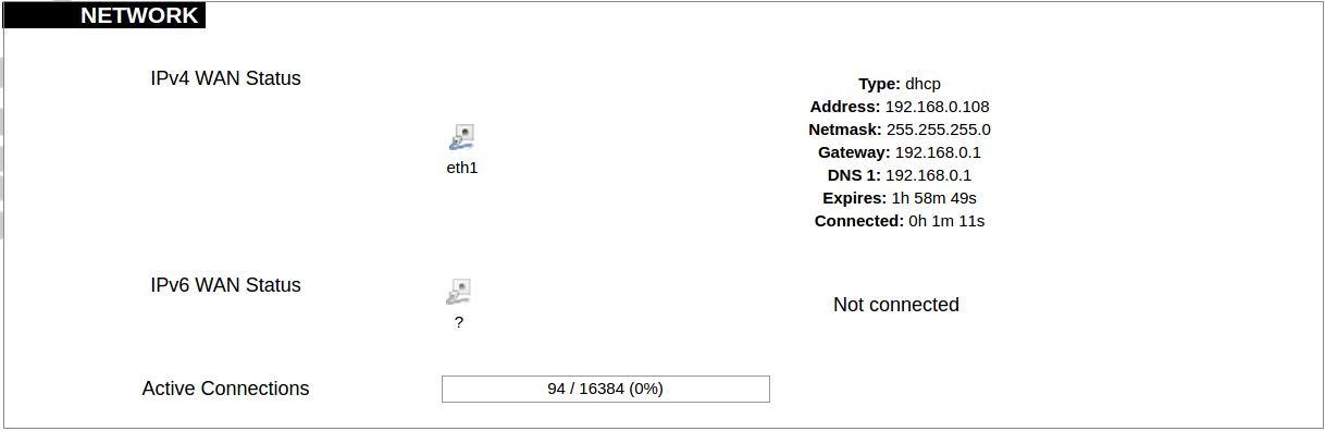
IPv4 WAN, IPv6 WAN status, and active connections of the device.
Type: Type of addressing of IPv4 network interface – DHCP or static.
Address: IP address of the device.
Netmask: Netmask of the device.
Gateway: IP address of the Gateway.
DNS: IP address of DNS server.
Expires: DHCP lease expiration time of the connection.
Connected: The time a device has been connected.
Active Connections: The number of active connections with the device.
Interfaces

Shows the IP of every active interface connection.
DHCP leases
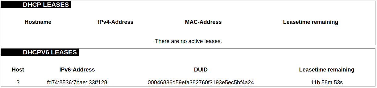
DHCPv4 and DHCPv6 lease expiration time.
Hostname: The label that is used to identify the device in the network.
IPv4-Address: IPv4 address of network interface.
MAC-Address: The media access control address of the IPv4 network interface.
DUID: DHCP Unique Identifier of IPv6 network interface.
Lease Time remaining: The amount of time the device will be allowed to connect to the Router.
Wireless

WiFi interface information window.
SSID: The sequence of characters that uniquely names a wireless local area network.
Mode: Shows how the device is connected to the wireless network – Master or Client.
Channel: The number of channels and radio frequency for connection to the access point.
Bitrate: The number of bits that pass the device in a given amount of time.
BSSID: The MAC address of the wireless access point.
Encryption: Security protocol for the wireless network.
Associated stations
 List of associated stations (clients).
Network: Mode and SSID of network point.
MAC-Address: The media access control address of the IPv4 network interface.
Hostname: The label or IP address that is used to identify the device in the network.
Signal/Noise: Received signal level over the background noise level. -30 dBm is the maximum achievable signal strength, and -70 dBm is the minimum signal strength for reliable packet delivery in the wireless network.
RX Rate/TX rate: Used to measure data transmission in the wireless network over bandwidth. RX Rate represents the rate at which data packets are received by the device, and the TX Rate represents the rate at which data packets are sent from the device.
Board information
 Board information provides the following details:
Hardware version: Current hardware version;
Serial number: Serial number of the board;
SoC ID: Unique identifier of CPU unit;
Firewall
IPv4 Firewall
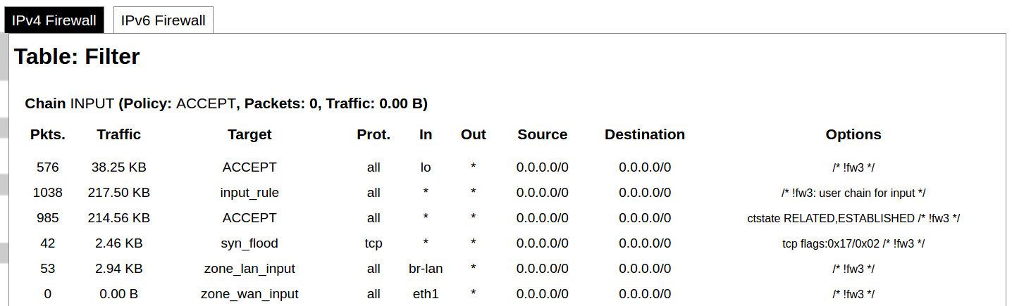
Firewall rule list for IPv4 traffic.
Table: The four distinct tables which store rules regulating operations on the packet. Filter concerns filtering rules. NAT concerns the translation of source or destination addresses and ports of packages. The mangle table is for specialized packet alteration. The raw table is for configuration exceptions.
Chain: The list of rules. Filter table has the following built-in chains: Input – concerns packets whose destination is the firewall itself, Forward – concerns packets transiting through the firewall, Output – concerns packets emitted by the firewall, Reject – reject the packet, Accept – allow the packet to go on its way. NAT table has the following built-in chains: Prerouting – to modify packets as soon as they arrive, Postrouting – to modify packets when they are ready to go on their way. Mangle table has one built-in chain: Forward for transiting packets through the firewall.
Pkts.: The packets are processed by the firewall.
Traffic: The amount of data processed by the firewall.
Target: The chain of the table of the firewall.
Prot.: The transport layer protocol is processed by the firewall.
In: The network interface for the input chain processed by the firewall.
Out: The network interface for the output chain is processed by the firewall.
Source: IPv4 address of the device that the packet comes from.
Destination: IPv4 address of the device that the packet goes to.
Options: The options for configuring the firewall.
IPv6 Firewall
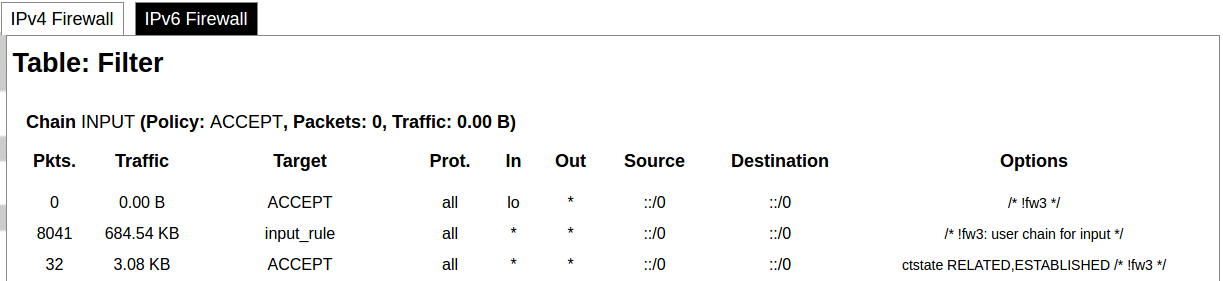
Firewall rule list for IPv6 traffic.
Table: The three distinct tables which store rules regulating operations on the packet. Filter concerns filtering rules. The mangle table is for specialized packet alteration. The raw table is for configuration exceptions.
Chain: The list of rules. Filter table has the following built-in chains: Input – concerns packets whose destination is the firewall itself, Forward – concerns packets transiting through the firewall, Output – concerns packets emitted by the firewall, Reject – reject the packet, Accept – allow the packet to go on its way. Mangle table has one built-in chain: Forward for transiting packets through the firewall.
Pkts.: The packets are processed by the firewall.
Traffic: The amount of data processed by the firewall.
Target: The chain of the table of the firewall.
Prot.: The transport layer protocol is processed by the firewall.
In: The network interface for the input chain processed by the firewall.
Out: The network interface for the output chain is processed by the firewall.
Source: IPv6 address of the device that the packet comes from.
Destination: IPv6 address of the device that the packet goes to.
Options: The options for configuring the firewall.
Routes
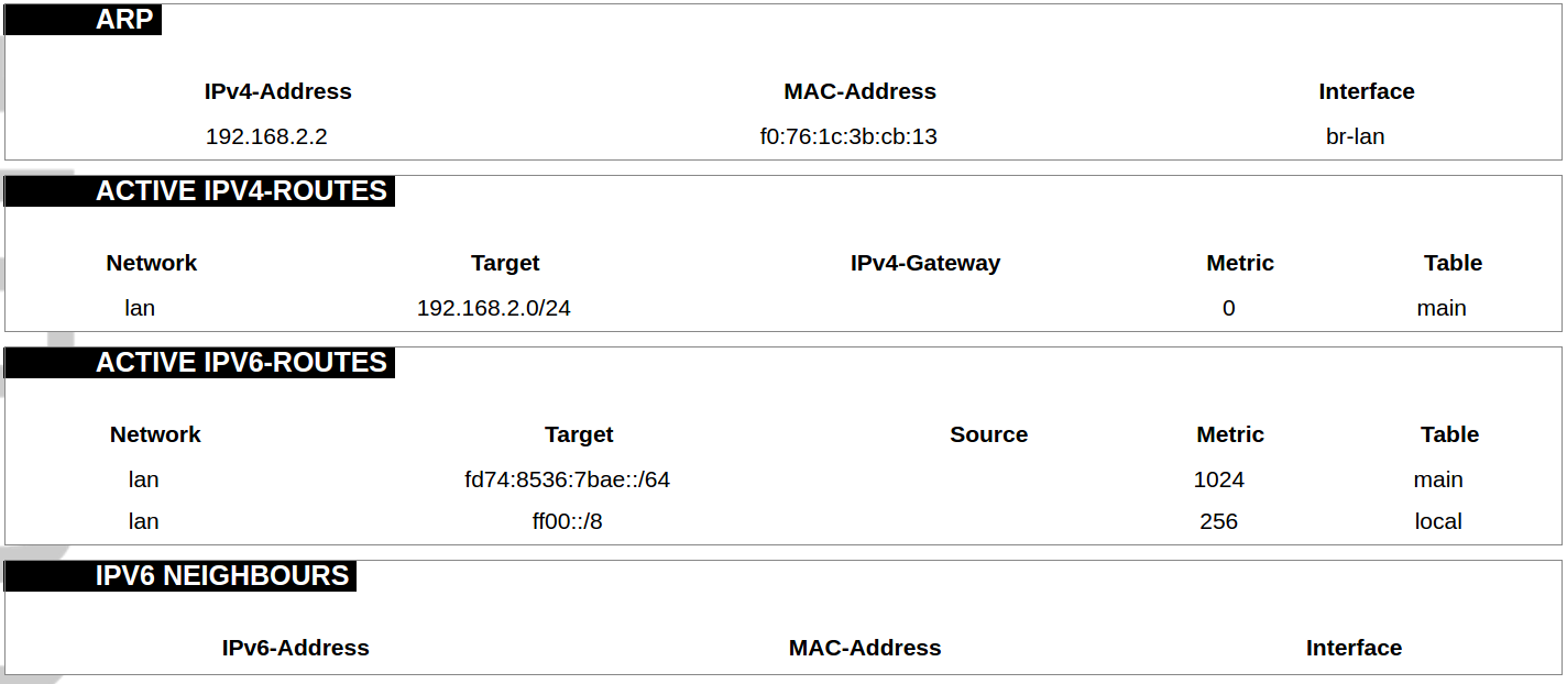
The routing tables provide information on how datagrams are sent to their destinations.
ARP: An address Resolution Protocol which defines how the IP address is converted to a physical hardware address needed to deliver packets to the devices.
Interface: The type of Network interface. br-lan refers to the virtual bridged interface: to make multiple network interfaces act as if they were one network interface.
Network: The type of network through which the traffic will be sent to the destination subnet.
Target: An address of the destination network. The prefix /24 refers to the subnet mask 255.255.255.0.
IPv4-Gateway: IP address of the gateway to which traffic intended for the destination subnet will be sent.
Metric: The number of hops required to reach destinations via the gateway.
Table: The type of routing tables: main (default), local (maintained by the kernel).
IPv6 Neighbours: The devices on the same network with IPv6 addresses.
System Log
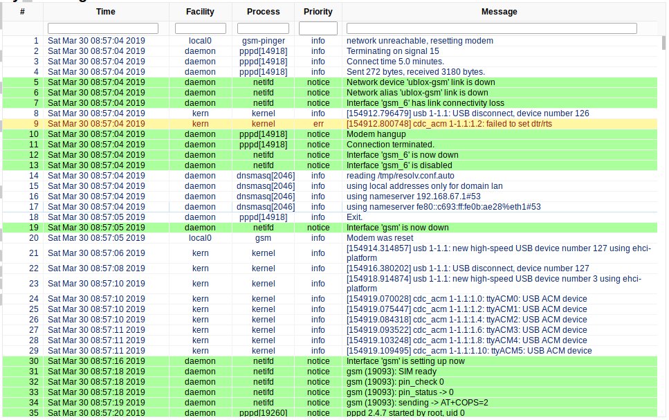
The system log window shows a table containing the events that are logged by the device. It has the following columns:
- # (sequence number);
- Time (day of the week, month, day of the month, time and year);
- facility;
- process (who generated the message);
- priority level;
- message.
Messages can be sorted and filtered to extract a particular set of messages. This might be useful when debugging kernel or protocol-level problems.
Kernel Log
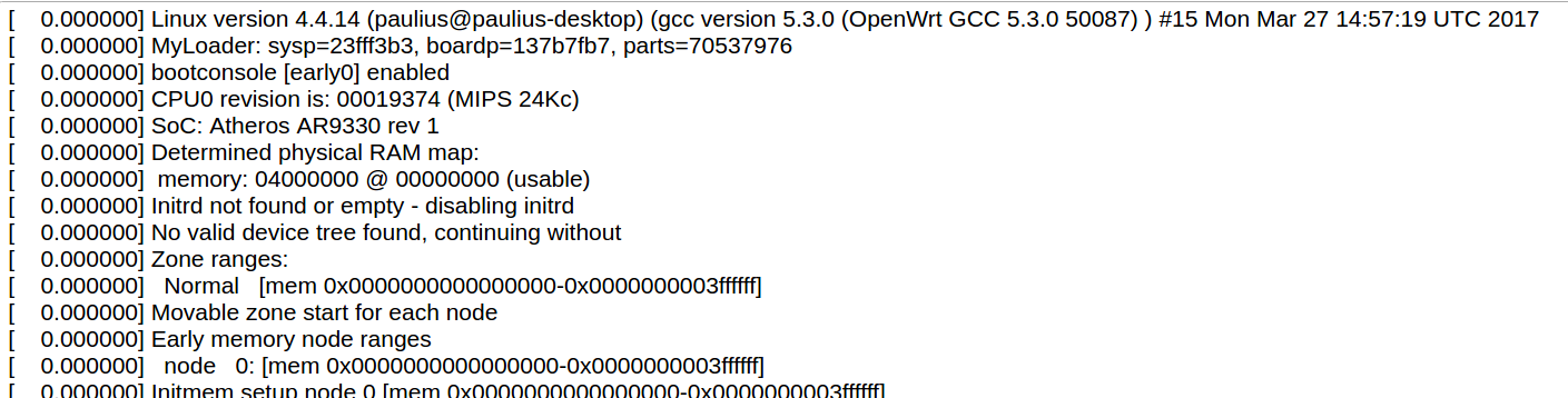
The kernel log shows a list of the events that are logged by the kernel of the device. Log format: time in seconds since the kernel started and message.
Chronos
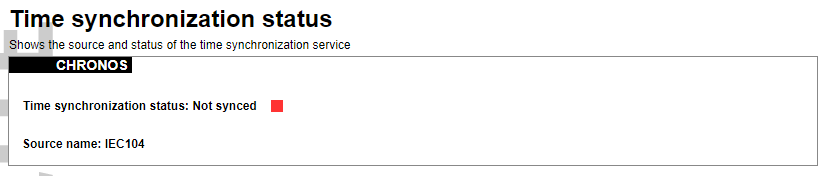
Shows the source and status of the time synchronization service.
Processes
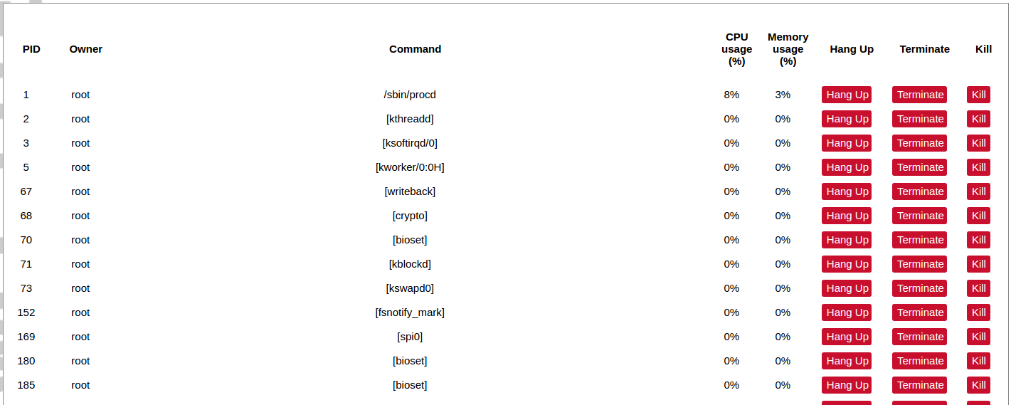
List of processes running on the system.
PID: Process ID.
Owner: User to whom the process belongs.
Command: Process.
CPU usage: It is the CPU usage of the individual process. CPU usage above 90 % is an indicator of insufficient processing power.
Memory usage: Memory usage of the individual process.
Hang Up: To freeze the process.
Terminate: To end the process cleanly.
Kill: To end the process immediately.
Realtime graph
Realtime Load
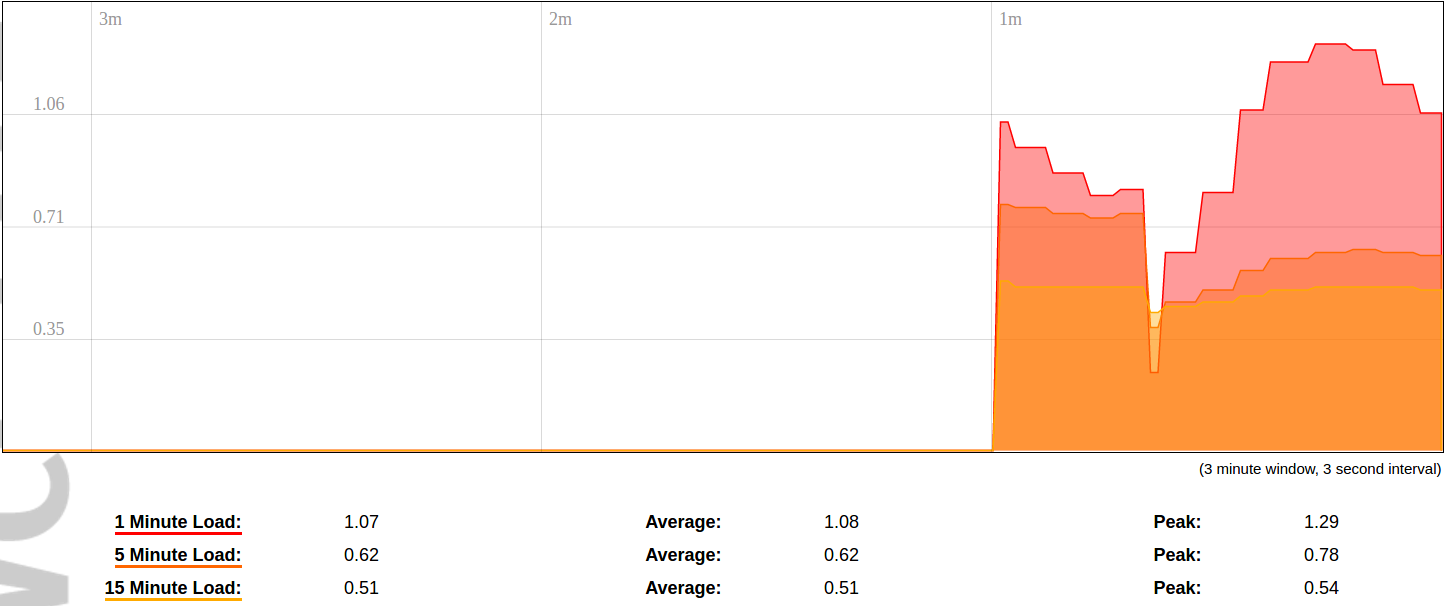
CPU utilization graph. A load of 0.5 means the CPU has been 50% utilized over the last period. Values over 1.0 mean the system was overloaded.
Realtime Traffic
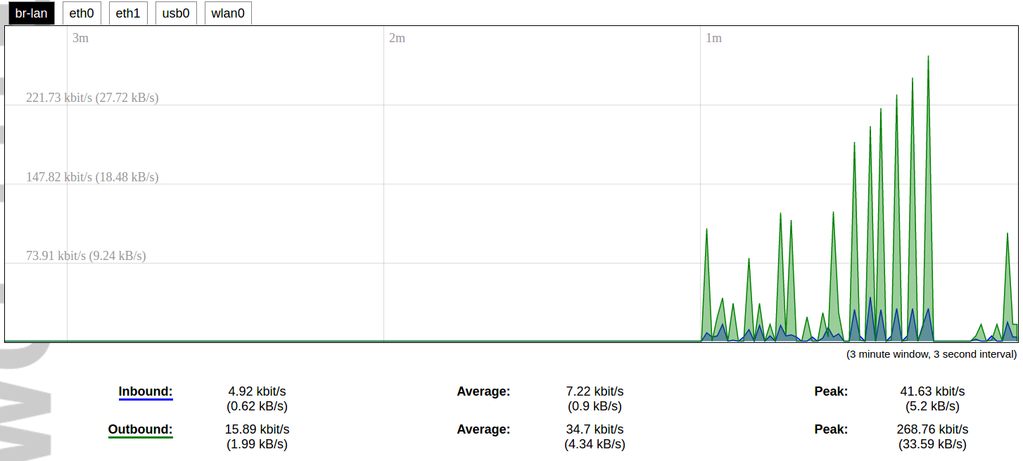
Graphs representing the status of the virtual and physical network interfaces of the device.
Inbound: The speed at which the incoming packets arrive at the device.
Outbound: The speed of the packets which were originated by the device.
Phy. Rate: The speed at which bits can be transmitted over the physical layer.
Realtime Wireless

WiFi status graph.
Signal: Signal strength level.
Noise: Noise level.
Phy. Rate: The speed at which bits can be transmitted on the physical layer.
Active connections
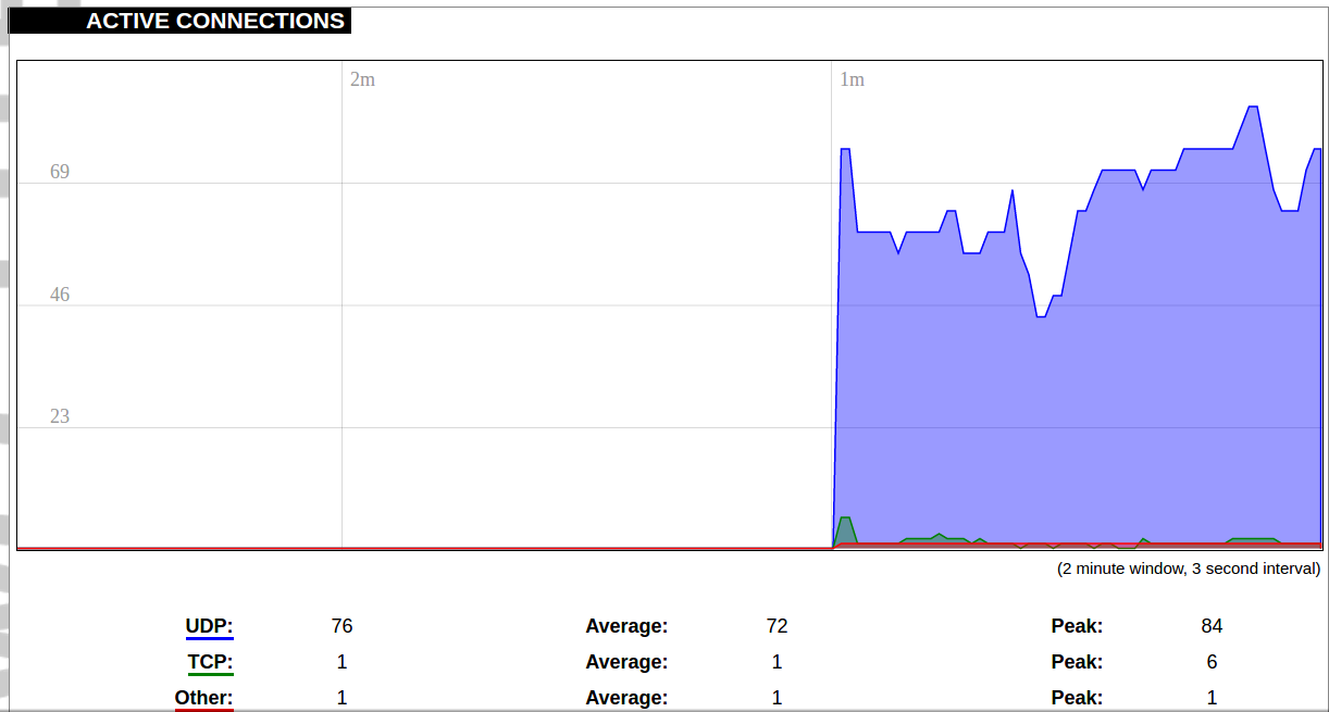
Graph representation of active connections with the device.
UDP: Transport layer – User Datagram Protocol.
TCP: Transport layer – Transmission Control Protocol.
Network: Type of the network layer – IPv4 or IPv6.
Source, Destination: IP address and the port number.
Transfer: The amount of the transferred data in kB and packets.
Realtime GSM Signal Quality
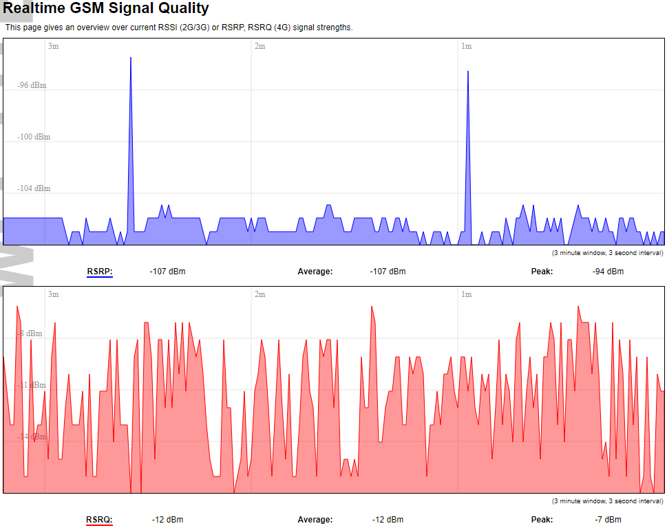
Graph representation of gsm modem receiving signal quality. RSRP - RSRQ graph is shown, when connected to 4G/LTE network, RSSI - when 2G/3G networks are used.
RSSI: Received Signal Strength Indicator in dBm.
RSRP: Received Signal Reference Power in dBm.
RSRQ: Received Signal Reference Quality in dBm.
GSM status
This page shows all information that is related to the GSM modem.
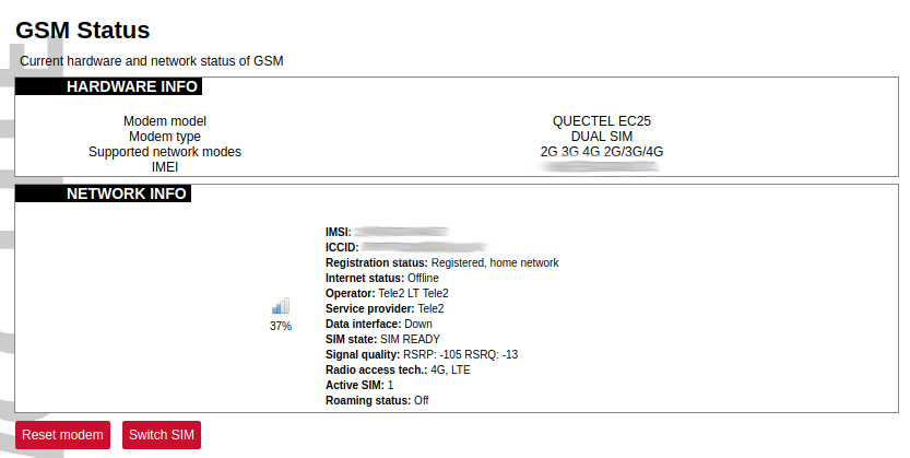
Hardware info
All static information on the GSM modem.
Modem model: Manufacturer and model of present modem.
Modem type: Single SIM or Double SIM modem.
Supported network modes: Shows which network modes (or their combinations) are supported (e.g. 2G 4G 2G/4G).
IMEI: IMEI (International Mobile Equipment Identity number).
Network info
All dynamic information on the GSM modem and connected network.
IMSI: IMSI (International Mobile Subscriber Identity) number related to the current SIM card user.
ICCID: ICCID (Integrated Circuit Card Identifier) number related to a physical SIM card.
Registration status: Curren status of network connection.
Internet status: Status of connection to the internet ( valid, when gsm-pinger is enabled and can reach provided hosts).
Operator: Operator’s name, to which modem is currently connected.
Service provider: IMEI (Service provider for SIM card. Data interface: Shows, whether WCC Lite has a data connection through gsm or not (possible values: ”Up”, ”Down”).
SIM state: Shows the current status of the SIM card (needs PIN, needs PUK, not inserted etc.).
Signal quality: Shows current signal strength value in dBms. The RSSI value is shown when connected to 2G/3G networks, and RSRP-RSRQ values - when connected to 4G networks.
Radio access tech.: Current radio technology used (2G, 3G, or 4G).
Active SIM: Shows which SIM card is active (if the modem is Dual SIM).
Roaming status: Current status of roaming (”Off”, ”On”).
Little bars with a percentage at the center-left shows signal strength. It is calculated with the respect to current radio access technology used (RSSI or RSRP). Two buttons at the bottom can reset (cold-reset) the modem or manually switch SIM cards (if it is a Dual SIM modem and both cards are enabled).

Signal quality is described in different ways for different types of mobile services: Received Signal Strength Indication (RSSI) in GSM (2G) and UMTS (3G), the Reference Signal Received Quality (RSRQ) in LTE RAT.
The Reference Signal Received Power (RSRP) is an LTE-specific measure that averages the power received by the subcarriers carrying the reference signal. The RSRP measurement bandwidth is equivalent to a single LTE subcarrier: its value is therefore much lower than the total received power usually referred to as RSSI. In LTE the RSSI depends on the currently allocated bandwidth, which is not pre-determined. Therefore the RSSI is not useful to describe the signal level in the cell.
VNSTAT Traffic monitor
To monitor the traffic of various network interfaces VNSTAT Traffic monitor can be used. Traffic tracking can be useful if the user wants to have precise information on how much data is used because it can have a dependency on data transmission costs, for example, mobile (cellular) data.
Graph

An example graph shows the statistics gathered for two network interfaces. In these graphs:
eth1: Network interface (e.g. Ethernet).
br-lan: Virtual network interface (bridge).
rx: Data packets received by the device.
tx: Data packets sent from the device.
Configuration
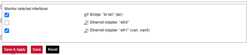
Interfaces to be monitored can be selected in a configuration screen. It includes all the network interfaces configured in a system. To start or stop monitoring user should either select or unselect the respective checkbox and save settings by pressing Save & Apply.
8.5 System
System
The system tab includes various properties, configurations, and settings of the system and contains the following pages:
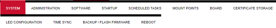
• SYSTEM: properties and settings of the system.
• ADMINISTRATION: settings of the administration for various services.
• SOFTWARE: settings of the packages.
• STARTUP: process management.
• SCHEDULED TASKS: settings of the scheduled tasks.
• MOUNT POINTS: settings for the mount points.
• BOARD: board configuration.
• CERTIFICATE STORAGE: certificate management panel.
• LED CONFIGURATION: settings for the LEDs.
• TIME SYNC: time synchronization of WCC Lite
• BACKUP/FLASH FIRMWARE: management of the configuration files and firmware image upgrade.
• REBOOT: device reboot page.
System
Basic aspects of the device can be configured. These include time settings, hostname, system event logging settings, language and theme selection.
System Properties
General Settings
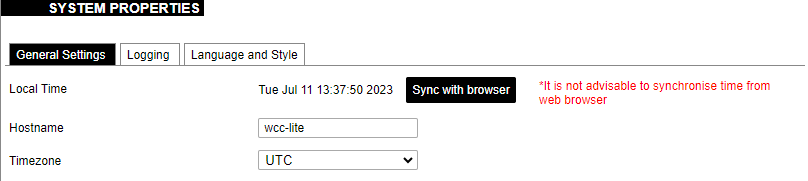
The general settings of the WCC Lite device are defined as follows:
Local Time: Current local time.
Hostname: The label that is used to identify the device in the network.
Timezone: A region of the globe that observes a uniform standard time. The time zone number indicates the number of hours by which the time is shifted ahead of or behind UTC – Coordinated
Universal Time. Some zones are, however, shifted by 30 or 45 minutes.
Logging
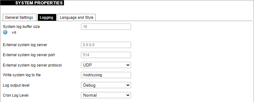
Logging settings of the WCC Lite device are defined as follows:
System log buffer size: The number of records that are recorded before writing these data to the disk.
External system log server: IP address of the server.
External system log server port: An endpoint of communication with the server.
External system log server protocol: A standard that defines how to establish and maintain a network connection: UDP - User Datagram Protocol, TCP - Transmission Control Protocol.
Write system log to file: The name of the file with the path to it.
Log output level: Log output messages can be grouped by their importance to the user. Levels are described in the table below.
| Log output level | Description |
| Emergency | System is unusable |
| Alert | Action must be taken immediately |
| Critical | Critical conditions |
| Error | Error conditions |
| Warning | Potentially hazardous conditions |
| Notice | Normal conditions that might need action |
| Info | Information messages |
| Debug | Debugging messages |
Cron Log Level: Cron has three output levels to choose from when writing to its logs. Possible options are
described in the table below.
| Cron log level | Description |
| Debug | Debugging messages |
| Normal | General administrative messages |
| Warning | Potentially hazardous conditions |
Language and styles
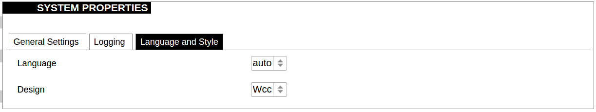
Language and Style settings are defined as follows:
Language: The language of the Web interface of the device.
Design: The theme of the Web interface of the device.
Administration
Administrator Password
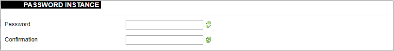
The administrator password can be changed. To change it the combination of digits and letters of the alphabet should be entered and then confirmed in the confirmation field by typing in again.
It is advised not to use the default password.
Password policy
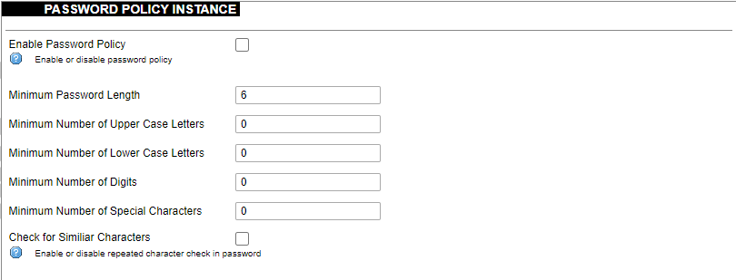
Users can configure a password policy for future password changes to create a safer password. Here password requirements can be made such as minimum password length, minimum number of upper or lower case letters, digits and special characters. By ticking the box for checking similar characters, a new password will be required not to have repeated characters.
SSH Access
WCC Lite has a compact secure shell (SSH) server named Dropbear. Multiple options are available to be changed via the WCC Lite web interface, ranging from automatic firewall rules to authentication flexibility.
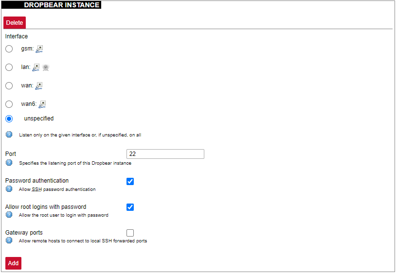
Dropbear options are defined as follows:
Interface: Listen only on the given interface or on all, in unspecified.
Port: Specifies the listening port of this interface.
Password authentication: Allow SSH password authentication.
Allow root logins with password: Allow the root user to log in with the password.
Gateway ports: Allow remote hosts to connect to local SSH forwarded ports.
SSH-keys

SSH keys can be added via the WCC Lite web interface. They might be helpful if the user logs into the device frequently and does not want to always have to write his credentials.
Login Attempt limiter
This feature is available from firmware version 1.9.1
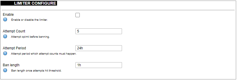
Enforce a limit of invalid access attempts and deny access from a virtual port for a set time.
RADIUS Client
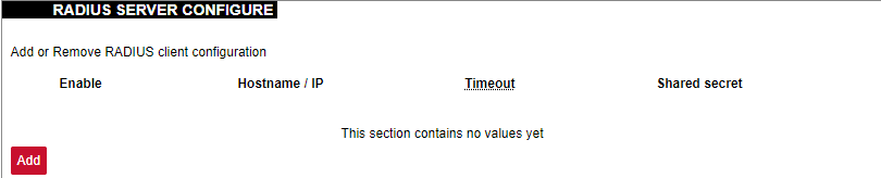
RADIUS client redirects user authorization to a remote server, which controls users and their access. A user can add multiple RADIUS clients by clicking add and entering the information required.
HTTPS certificate

WCC Lite by default is shipped with a default certificate for HTTPS connection. This certificate only enables connecting to the device via a web interface and might cause warnings from a web browser. To eliminate them, the user can use his certificate to secure access to the web interface.
Users can use certificates uploaded to a certificate storage. It should be noted that only valid certificates with *.pem extension can be used. The certificate to be used is validated every time the device is restarted.
If validation fails, a default certificate is used. This is done to prevent users from losing device access via the web interface.
For the new certificate to come into effect user should restart the device.
Software
Individual packages can be installed via the WCC Lite web interface. They can either be installed using a web link or selected from the pre-defined feeds.
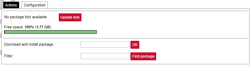
Various options can be selected when installing packages, however, default ones should work well enough and it’s advised only to change them for advanced users.

Feeds from which packages are listed for the update are defined in the Open PacKaGe management (OPKG) configuration that can be changed easily from the user interface.
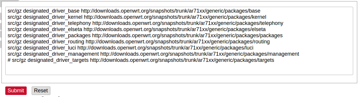
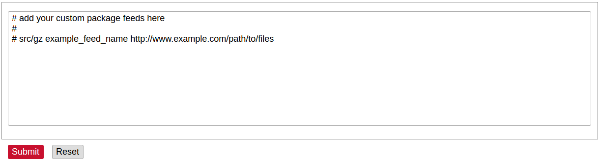
Specific distribution feeds can also be added for special cases if standard ones do not fit the needs.
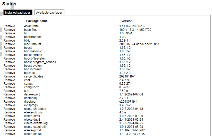
The installed packages tab indicates every installed package in alphabetical order. Users can also remove certain packages by clicking the Remove button on the left.
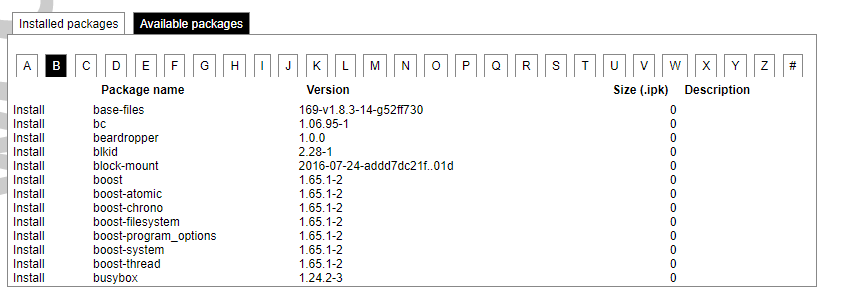
In this tab, the user can search for a package by the first letter of its name. Those packages are available but not installed, so the user can choose to install them by clicking on the Install button on the left.
Startup
All of the processes that have init.d scripts can optionally be enabled or disabled. This can be very useful if the user intends to use only part of the processes.
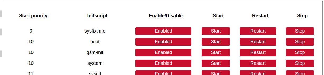
Users should not disable processes that are essential for device operation as it can render the device unusable.
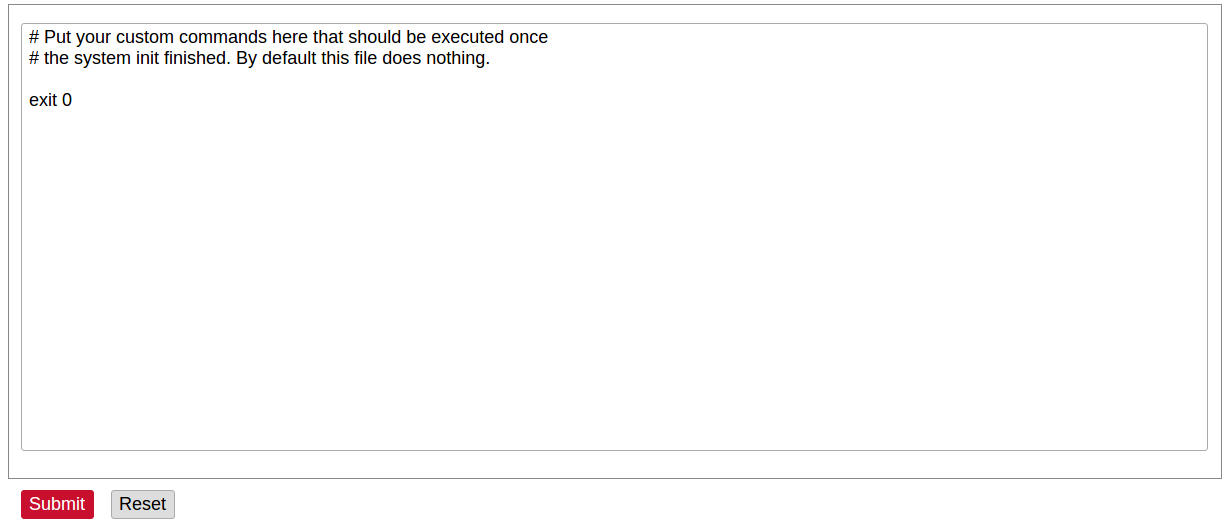
Users can optionally run scripts and programs on device startup by putting them into a /etc/rc.local file. This file can be updated from the WCC Web interface.
Scheduled tasks

Various tasks can be scheduled with the system crontab. New tasks can be included by creating and saving new rules conforming to cron rules. WCC Lite accepts full cron configuration functionality.
The example in the pictures shows how to execute the disk usage command to get the directory sizes every 6 p.m. on the 1st through the 15th of each month. E-mail is sent to the specified email address.
Mount points
Global settings
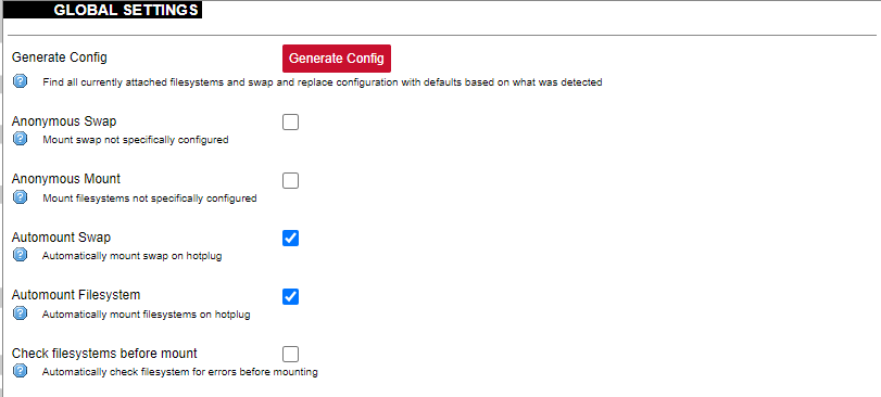
File system mount point configuration window.
Generate Config: Find all currently attached filesystems and swap and replace configuration with defaults based on what was detected.
Anonymous Swap: Mount swap not specifically configured.
Anonymous Mount: Mount filesystems not specifically configured.
Automount Swap: Automatically mount swap on hotplug.
Automount Filesystem: Automatically mount filesystems on hotplug.
Check filesystems before mount: Automatically check the filesystem for errors before mounting.
Mounted file systems
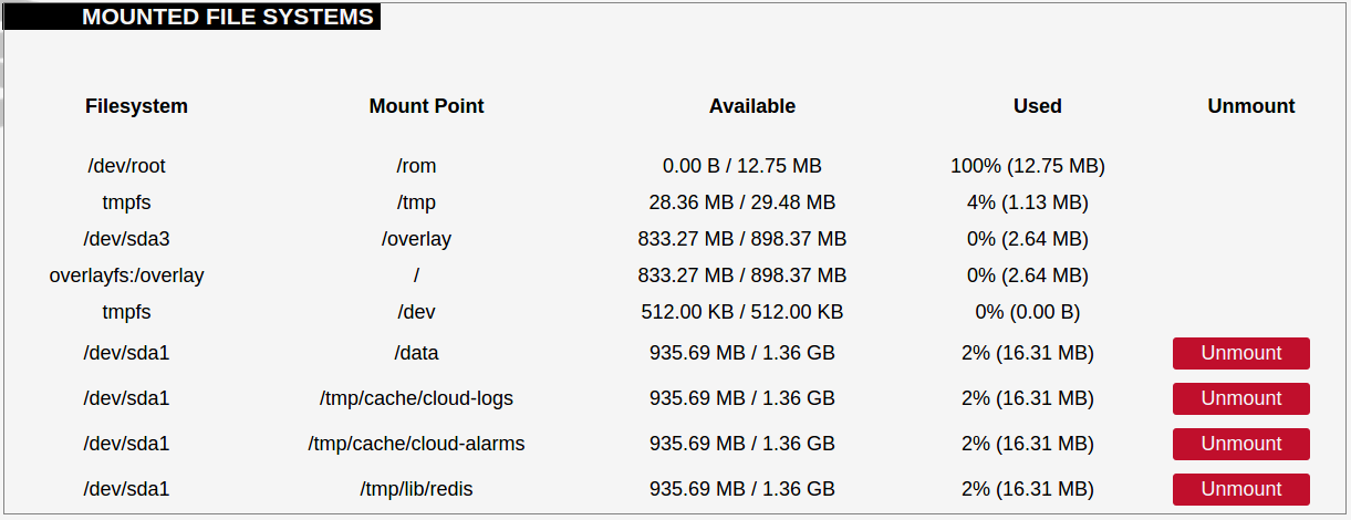
List of mounted file systems, some of which can be dismounted manually.
Mount points
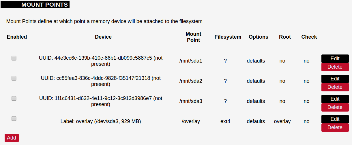
List of mount points which can be enabled, disabled or deleted.
Swap
The swap section is used to describe the virtual memory that can be used if there’s a lack of main memory. WCC Lite does not use any virtual memory by default.
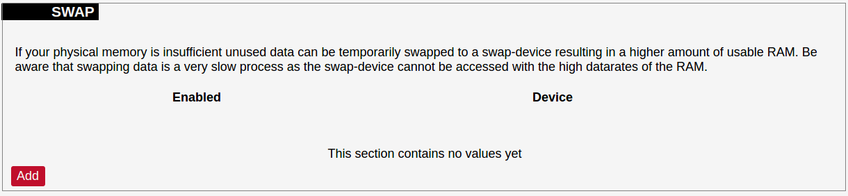
It should be noted that virtual memory might do a lot of reading and writing operations. As WCC Lite uses an SD card as an additional flash memory, it is highly advised to not use a swap to reduce wearing.
Board
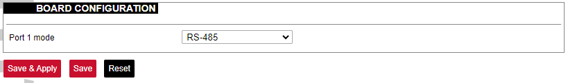
Here a user can configure PORT1 as RS-485 or RS-232.
Certificate storage
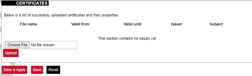
This section is intended to upload certificate files and view information about them.
LED configuration
WCC Lite has three LEDs that can be configured: WAN, LAN and WLAN. All of the LEDs have a default configuration which should fit most of the cases.
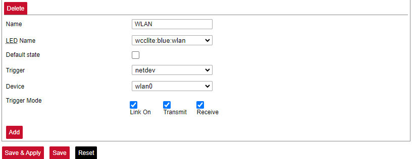
All possible LED configuration options: Name: Name of the LED configuration.
LED Name: Colour and location of the LED. These can be changed, however, normally they should be left unchanged.
Default state of the LED: On/Off.
Trigger: One of the various triggers can be assigned to an LED to change its state. Possible values are shown in the table below.
Table. Possible trigger for an LED:
|
Trigger type |
Description |
|
none |
No blinking function assigned to the LED |
|
defaulton |
LED always stays on |
|
timer |
Blinking according to a predefined timer pattern |
|
heartbeat |
Simulating actual heartbeats |
|
nand-disk |
Flashed as data is written to flash memory |
|
netdev |
Flashes according to link status and send/receive activity |
|
phy0rx, phy0tx, phy0radio, phy0tpt, phy0assoc |
Flashed on WiFi activity events |
|
usbdev |
Turned on when the USB device is connected. Applicable for modems |
Device: Network interface which is going to be tracked.
Time sync
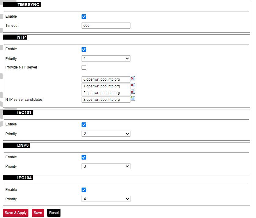
This service syncs WCC Lite time with the protocols shown. Here user can also select priority levels of protocols which sync with WCC Lite.
Time synchronization configuration
The time synchronization configuration allows users to set protocol priorities when multiple protocols are connected to WCC Lite. The TIMESYNC function also enables users to define a timeout period.
Based on the assigned priorities, each protocol attempts to synchronize WCC Lite, starting with the highest priority -1. If synchronization is unsuccessful within the defined timeout, the next protocol in the priority list is used.
If the first protocol successfully synchronizes WCC Lite, the timeout is reset, and the first protocol retains its priority. If the first protocol fails, the system moves to the second protocol. In this case, both the first and second protocols remain available for synchronization.
This process continues through the priority list. If synchronization reaches the last protocol on the list, all four protocols will be available to synchronize WCC Lite.
WCC Lite has an NTP client to synchronize dates and times with external sources. It is not the only source for synchronization, it can also be done using methods defined in IEC-60870-5 protocols.
Please take care choosing a time sync method. If both NTP and IEC 60870-5 protocol slave interface time sync methods are activated simultaneously, they can interfere if there is a time difference. We strongly recommend using a single-time sync method to prevent time interference.
Time synchronization options are defined as:
Enable NTP client: The local time of the device will sync with external time servers.
Provide NTP server: Turn the device into a local NTP server.
NTP server candidates: The network time protocol servers.
Backup/flash firmware
Software update allows to upgrade of the software running in WCC Lite. It is recommended to keep the device up to date to receive the latest features and stability fixes.
Backup archives contain complete WCC Lite configuration that can be restored at any time. A file will be downloaded by your browser when creating a backup. This file can be later uploaded to the web page to restore configuration.
The generated backup archive should only be applied to the same firmware version it was generated. Applying backup to a different firmware version might render some parts of the operating system unstable or even unusable
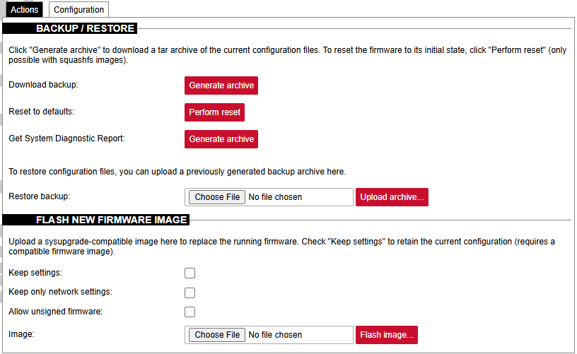
Since version 1.8.3, users can save network settings before upgrading the firmware, such as firewall settings, traffic rules, interfaces etc. To do so, before upgrading firmware, the "Keep only network settings:" box should be checked.
Since version 1.10 all firmware files are signed and have different file extensions. If there is a need to downgrade a firmware version from 1.10, the Allow unsigned firmware box should be checked.
A user can choose to keep existing settings after an upgrade. Marking the Keep Settings checkbox preserves files listed in /etc/sysupgrade.conf and /lib/upgrade/keep.d/. It is advised to do a clean install and use backup files to restore settings later if a user intends to make a major system upgrade.
Uploading firmware images, to preserve RAM, will stop all Protocol HUB processes. After upload, you will have 2 minutes to proceed with firmware flash or to cancel it. After 2 minutes, the firmware file will be deleted and Protocol HUB processes will be restarted.
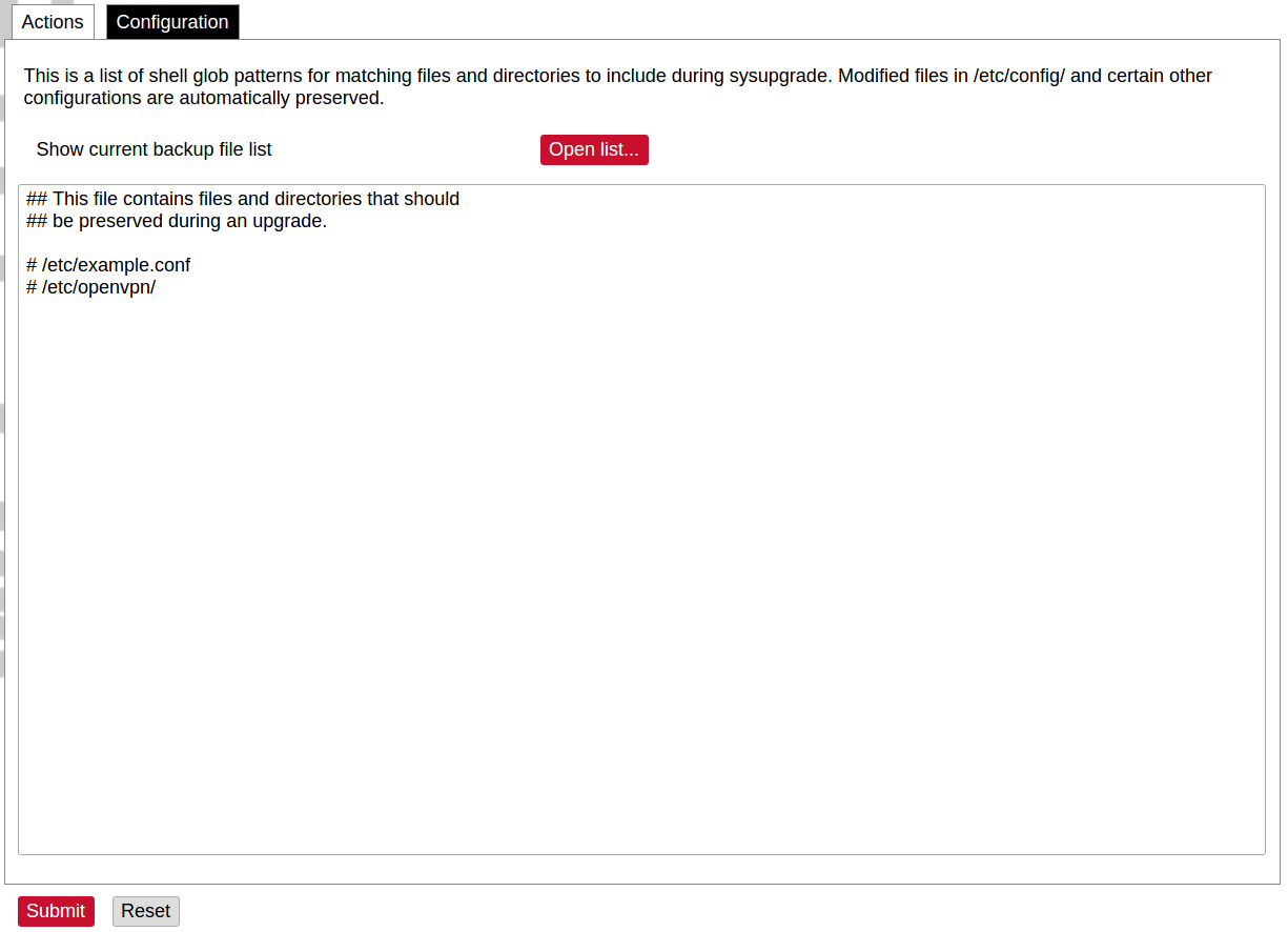
A file name /etc/sysupgrade.conf can be updated via the WCC Web interface. To preserve additional files user should add them to the backup file and press Submit. To get the whole list of files that would be backed up press Open list... It is advised to check it before doing a backup or an upgrade while keeping settings.
Reboot
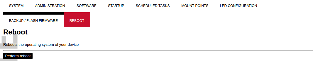
This reboots the operating system of the device.
8.6 Services
The services tab shows the services of the device and contains the following subsections:

The services tab shows the services of the device and contains the following subsections:
- TELEMETRY AGENT: device telemetry sent to a remote server;
- IPSEC: encrypted virtual private network (VPN) configuration.
- API: application programming interface configuration.
- OPENVPN: shows the open-source software application that implements a virtual private network (VPN).
- SER2NET: network-to-serial proxy;
Telemetry agent
Having data about the device helps to easily maintain it. Telemetry agent gathers information in a compact and easily decodable way. It uses UDP packets therefore only a small overhead is introduced.
However, UDP does not guarantee the arrival of sent packets therefore not every message might reach the server saving these messages.
To start using a Telemetry agent a user should configure and enable it. Four options are available:
- Enable agent;
- Server address;
- Port (UDP);
- Period (s).
Every time the timer of period length expires, a message is sent to a server of the configured server if the service is enabled.
The telemetry agent doesn’t start as a service if the Enable agent checkbox is unchecked.
Enabling the agent and saving the configuration automatically starts the process with the new configuration.
IPsec
Background
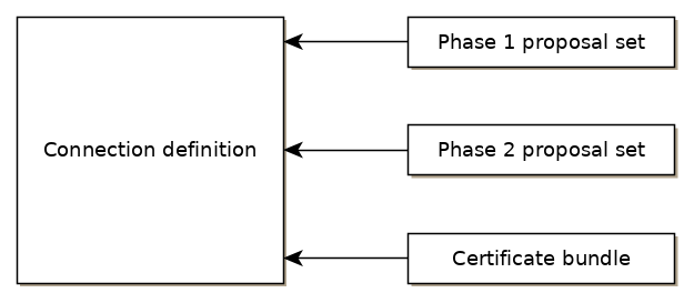
WCC Lite supports ipsec VPN and thus can deliver data securely over encrypted links. To establish ipsec vpn, a connection definition must be created by entering the appropriate configuration settings.
For advanced connection description auxiliary settings sets can be defined. They can be joined to the connection and can be reusable several times according to the need. Each configuration record is identified by a unique name, which is assigned at the time of creation. The following diagram shows the relations between connection and auxiliary sets.
Ipsec settings
Connection description
Options supported by WCC lite are described below.
| Item | Type | Description |
| Gateway | string | Host name or IP address of the remote peer. |
| Type | selector |
Tunnel mode: full packet encryption, covers host-to-host, host-to-subnet, subnet-to-subnet situations or transport mode: ip payload encryption, secures host-to-host data only. |
| Local subnet | string |
Specifies local network, in the form of network/netmask, for example 192.168.11.0/24 |
| Remote subnet | string | Specifies remote network at another side of a tunnel. |
| Authentication | selector | Pre-shared key or RSA certificate |
| Pre-shared key | string | Available if Authentication is set to Pre-shared key |
| Certificate set | selector |
Available if Authentication is set to RSA certificate. Selectable from the configured auxiliary set. |
|
Phase 1 proposal (IKE) |
selector |
Authentication-encryption schema, selectable from configured auxiliary set. |
|
Phase 2 proposal (ESP) |
selector |
Authentication-encryption schema, selectable from configured auxiliary set. |
|
Local ID |
string |
Specifies the identity of the local endpoint |
|
Remote ID |
string |
Specifies the identity of the remote endpoint |
|
Key exchange |
selector |
Sets method of key exchange IKEv2 or IKEv1. Default IKEv2. |
|
Exchange mode |
selector |
Main or aggressive. Available if key exchange is set to IKEv1. |
|
Use compression |
checkbox |
If selected a compression ability will be proposed to the peer. |
|
DPD action |
selector |
Controls the use of dead peer detection protocol, values:
|
|
DPD delay |
string |
Time interval in seconds between peer checks. Default 30. |
|
DPD timeout |
string |
Time in seconds after which peers consider it to be unusable. IKEv1 only. Default 150. |
|
Key lifetime |
string |
Lifetime of data channel in seconds. Default 10800. |
|
IKE lifetime |
string |
Lifetime of keying channel in seconds. Default 3600. |
Auxiliary settings
Phase 1 proposals - IKE/ISAKMP cypher suite components:
| Item | Type | Description | Note |
|
Encryption algorithm |
selector |
Encryption algorithm – 3DES, AES128, AES192, AES256. |
required |
|
Hash algorithm |
selector |
Hash algorithm – MD5, SHA1, SHA256, SHA384 or SHA512. |
required |
|
DH exponentiation |
selector |
Specifies Diffie-Hellman groups – 1,2,5,14,15,16,18 |
required |
Phase 2 proposals - ESP cipher suite components:
| Item | Type | Description | Note |
|
Encryption algorithm |
selector |
Encryption algorithm – 3DES, AES128, AES192, AES256. |
required |
|
Hash algorithm |
selector |
Hash algorithm – MD5, SHA1, SHA256, SHA384 or SHA512. |
required |
|
DH exponentiation |
selector |
Specifies Diffie-Hellman groups – 1,2,5,14,15,16,18 |
optional |
The following specification and topology map correspond to settings used in further configuration walk-through examples.
Creating a connection description
Site-to-Site VPN scenario

VPN connection details
Tunnel: demoo
IPSec peer: ipsec.vpn.net
Pre-shared key: thebigsecret
Mode: tunnel
Remote network: 10.10.10.10/24
Local network: 10.10.12.0/24
Local ID: wcclite
IKE authentication: aes256
IKE hash: sha256
IKE DH group: 5 (modp1536)
ESP authentication: aes128
ESP hash: sha1If auxiliary data is needed, it is recommended to check or define it first.
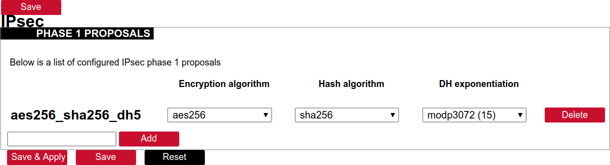
Creation of Phase 1 proposal
- Enter the section “Phase 1 proposals”.
- Create a new record by assigning a new name, for example, “aes256-sha256-dh5” and click the button “Add”.
- Choose corresponding values: encryption, hash algorithm and DH exponentiation.
- Push “save” to save the data.
Creation of Phase 2 proposal
- Enter the section “Phase 2 proposals”.
- Create a new record by assigning a new name for example “aes128-sha1” and click the button “Add”.
- Choose corresponding values: encryption, hash algorithm.
- Push “save” to save the data.

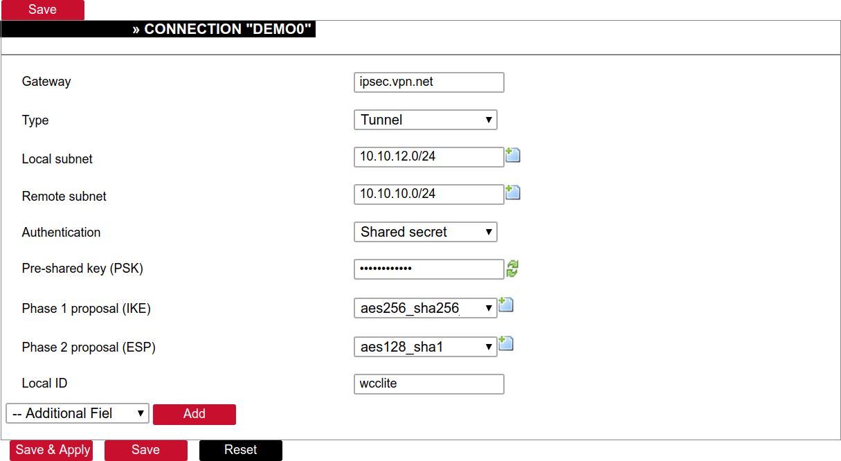
Creation of tunnel definition
Enter section connections
- Create a new record by assigning a new name (e.g.“demo0”) and clicking “Add”.
- Call a detailed form by pushing the button “edit”.
- Enter peer address into “Gateway”: “ipsec.vpn.net”.
- Ensure “Type” is set to: “Tunnel”.
- Fill local subnet to: 10.10.12.0/24.
- Fill remote subnet to: 10.10.10.0/24.
- Make sure authentication is set to: “Shared secret”.
- Enter Pre-shared key (PSK): thebigsecret.
- “Phase 1 proposal (IKE)”, choose a value: aes256_sha256_dh5.
- “Phase 2 proposal (ESP)”, choose a value: aes128_sha1.
- Locate the combo box “additional field”, select “Local ID”, then set the value to wcclite.
- Push “Save”.
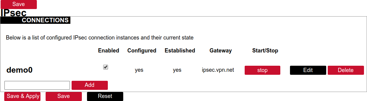
Activating the tunnel
-
Return to the section “connections”.
-
Check the checkbox “Enabled”.
-
Push the button “save & apply”.
-
Examine the indicator “configured”, it should be “yes”, if not, review the settings just entered.
-
The tunnel should be prepared for operation and will be established on demand.
-
Optionally, it is possible to establish tunnel operation by pressing the button “start”.
L2TP/IPsec
Because of the lack of confidentiality inherent in the L2TP protocol, it is often implemented along with IPsec. This is referred to as L2TP/IPsec and is standardized in IETF RFC 3193. The process of setting up an L2TP/IPsec VPN is as follows:
- Negotiation of IPsec security association (SA), typically through Internet key exchange (IKE). This is carried out over UDP port 500, and commonly uses either a shared password (so-called ”pre-shared keys”), public keys, or X.509 certificates on both ends, although other keying methods exist.
- Establishment of Encapsulating Security Payload (ESP) communication in transport mode. The IP protocol number for ESP is 50 (compare TCP’s 6 and UDP’s 17). At this point, a secure channel has been established, but no tunnelling is taking place.
- Negotiation and establishment of an L2TP tunnel between the SA endpoints. The actual negotiation of parameters takes place over the SA’s secure channel, within the IPsec encryption. L2TP uses UDP port 1701.
When the process is complete, L2TP packets between the endpoints are encapsulated by IPsec. Since the L2TP packet itself is wrapped and hidden within the IPsec packet, no information about the internal private network can be gathered from the encrypted packet. Also, it is not necessary to open UDP port 1701 on firewalls between the endpoints, since the inner packets are not acted upon until after IPsec data has been decrypted and stripped, which only takes place at the endpoints. A potential point of confusion in L2TP/IPsec is the use of the terms tunnel and secure channel. The term tunnel refers to a channel which allows untouched packets of one network to be transported over another network. In the case of L2TP/PPP, it allows L2TP/PPP packets to be transported over IP. A secure channel refers to a connection within which the confidentiality of all data is guaranteed. In L2TP/IPsec, first IPsec provides a secure channel, and then L2TP provides a tunnel.
API
The firmware of the WCC Lite features a built-in API which is accessible via the web interface.
As of version 1.2.11, it does not implement any access restriction features apart from those provided by the firewall functionality.
Individual API endpoints can be enabled or disabled via the web configuration interface at Services->API.
All endpoints are disabled by default.
Available API endpoints are shown in the table below.
Table. Available API endpoints:
| Endpoint | Description |
|
/api/version |
Version of the API |
|
/api/actions |
List of available points |
| /api/syncVersion |
A version of the sync service |
|
/api/sync |
Protocol hub configuration sync (name=”file”)* |
|
/api/syslog |
Prints out the syslog |
|
/api/systemInfo |
General system info |
|
/api/gsmInfo |
GSM modem information |
|
/api/devices |
List of configured devices |
|
/api/device/info |
Device information (name=”device_alias”)** |
|
/api/device/tags |
List of tags on a particular device (name=”device_alias”)** |
|
/api/device/tag/value |
Tag value (name=”device_alias”, name=”signal_alias”)** |
|
/api/tags |
List of configured tags |
|
/api/sysupgrade |
Firmware upgrade (name=”file”)* |
* Endpoints accepting files
** Endpoints accepting field data
The API accepts data and files as POST requests encoded as ”multipart/form-data”.
OpenVPN
OpenVPN Instances
The primary goal is to get a working WCC Lite tunnel and establish a basic platform for further customization. Most users will require further configuration tailored to their individual needs. If you are creating an OpenVPN server (either type), you must create security certificates using the instructions below. If you are using OpenVPN as a client, the required certificates should have been provided with your configuration details. OpenVPN can be configured either by using the WCC Lite Web interface or uploading the OVPN file containing the necessary parameters. OpenVPN will automatically attempt to load all *.conf files placed in the /etc/openvpn folder. Several OpenVPN recipes are suggested containing the most used configurations that may only require minor changes. If a user intends to set up OpenVPN without an OVPN file, it is highly advised to use these recipes and tweak them up to individual needs.
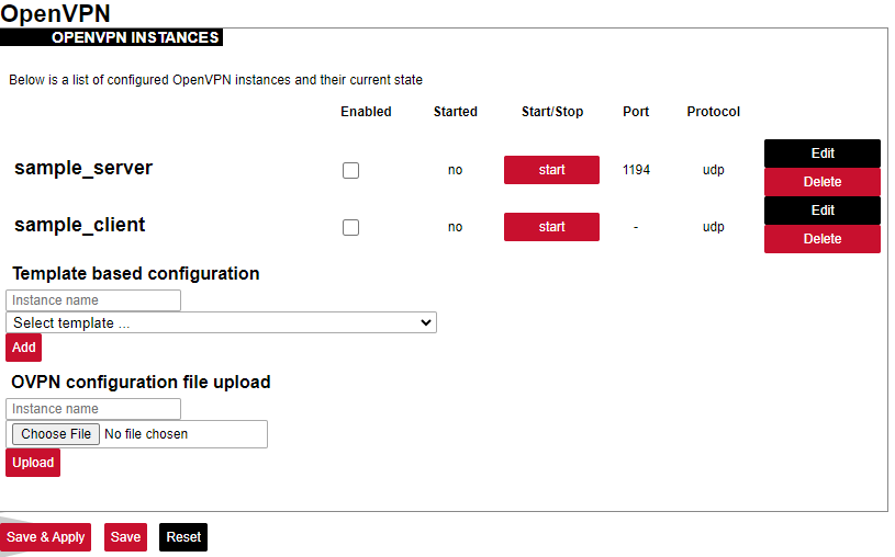
The OpenVPN instances page contains parameters to be configured.
Enabled: Flag to specify if a particular configuration should be enabled;
Started: Specifies if a particular configuration has been started by OpenVPN;
Port: Specifies the listening port of this service;
Protocol: A standard that defines how to establish and maintain a network connection: UDP - User Datagram Protocol, TCP - Transmission Control Protocol.
More parameters for every instance can be changed by pressing the Edit button, configuration can be removed with the Delete button. Pressing Edit takes the user to the main configuration screen containing the options usually used in particular OpenVPN recipes. To make more specific changes user should further select Switch to advanced configuration.
OVPN files contain configuration in a textual form therefore changing parameters requires having prior knowledge about different OpenVPN parameters. It is advised to use OVPN files, however, if the configuration has been pre-built beforehand and is used without further changes.
ser2net
The ser2net daemon allows telnet and tcp sessions to be established with a device’s serial ports. The program comes up normally as a daemon, opens the TCP ports specified in the configuration file, and waits for connections. Once a connection occurs, the program attempts to set up the connection and open the serial port. If another user is already using the connection or serial port, the connection is refused with an error message.
SNMP
SNMP (Simple Network Management Protocol) is an internet-standard protocol for managing devices on IP networks. SNMP exposes management data in the form of a hierarchy of variables in an MIB (Management Information Base).
WCC Lite supports SNMP service which is not added to the default build of firmware but can be installed as a module. It enables users to collect data on various parameters of the system:
• CPU time - time spent for calculations of various processes:
user - time for user processes;
system - time for system processes;
idle - time spent idling;
interrupts - time spent handling interrupts.
• CPU load average - CPU load average for 1, 5 and 15 minutes respectively;
• Disk usage:
total - the total amount of storage in the device (in kB)
available - amount of storage available to store data (in kB)
used - amount of storage used in the device (in KB)
blocks used percentage - blocks (sectors) used to store data in a disk (in kB)
inodes used percentage - the inode (index node) is a data structure in a Unix-style file system that describes a file-system object such as a file or a directory. Each inode stores the attributes and disk block location(s) of the object’s data.
• Memory usage - RAM usage statistics:
total - the total amount of RAM in the device (in kB);
available - unused amount of RAM in the device (in kB);
shared - shared amount of RAM between multiple processes (in kB);
buffered - refers to an electronic buffer placed between the memory and the memory controller;
cached - a portion of memory made of high-speed static RAM (SRAM) instead of the slower dynamic RAM (DRAM) used for main memory;
• Network interfaces:
MTU - maximum transmission unit to be sent over the network;
speed - the rate of network transmission;
physical address - unique MAC address assigned to a device;
tx/rx: byte, packet, drop, error count;
• System properties:
uptime - time since the device was turned on;
process uptime - time since the process has been started;
hostname - a label that is assigned to a device connected to a computer network;
name - name of the device (if defined);
location - location of the device (if defined).
8.7 Network

The page shows information about the current interface status, and its configurations, provides various interface, and network properties configuration capabilities and contains the following subsections:
• INTERFACES: shows information about current interface status, and allows for creating and configuring new ones.
• WIRELESS: shows information about wireless radio stations, and covers the physical settings of the wireless hardware.
• DHCP AND DNS: allows management of DHCP and DNS servers.
• HOSTNAMES: allows management of host names.
• STATIC ROUTES: allows management of IPv4 and IPv6 static routes.
• FIREWALL: allows management of firewall zones and various firewall properties.
• DIAGNOSTICS: provides network diagnostics utilities.
• GSM: allows management of GSM modem and SIM cards.
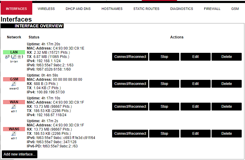
Interfaces
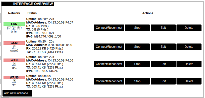
Current information and status of various network interfaces (GSM, LAN, WAN).
Uptime: The current interface uptime in hours, minutes and seconds.
MAC address: Physical interface address.
RX: Received data in bytes (packet count).
TX: Transmitted data in bytes (packet count).
IPv4: Internet protocol version 4 address.
IPv6: Internet protocol version 6 address.
In addition to the network interface status, several actions may be performed:
Connect/Reconnect: Connect to the configured interface network if it does not do it automatically. If it is already connected to the network it will be trying to reconnect to it.
Stop: Shutdown interface. If you are connected through this interface the connection may be lost.
Edit: Edit interface settings.
Delete: Delete interface.
Add new interface: Adding new Ethernet, GSM or wireless interface with the custom name, protocol, etc.
| eth0 | eth1 | |
| Type | Static | DHCP |
| Address | 192.168.1.1 | |
| Subnet mask | 255.255.255.0 | |
| Gateway |
Changes will only take effect after the device reboots.
Network interfaces can be configured on the common page, which can be accessed through adding a new interface or an edit button.
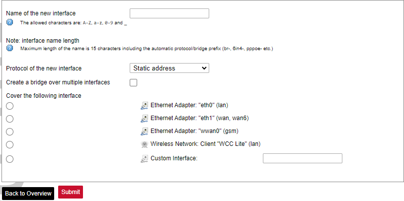
The following options can be defined in the interface creation panel: name of the interface, protocol, coverage of a particular interface or bridging with other interfaces. After the general setup is done, more detailed settings can be set.
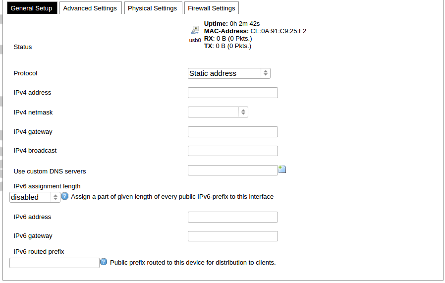
General common interface setup panel.
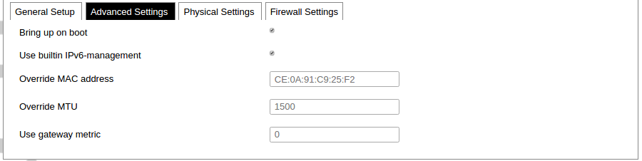
Advanced common interface setup panel.

Physical common interface setup panel.
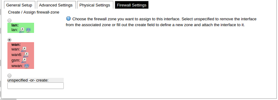
Firewall common interface setup panel.
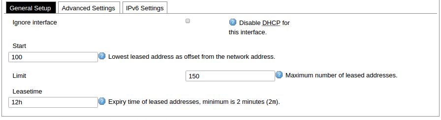
DHCP server general setup panel.

DHCP server advanced setup panel.
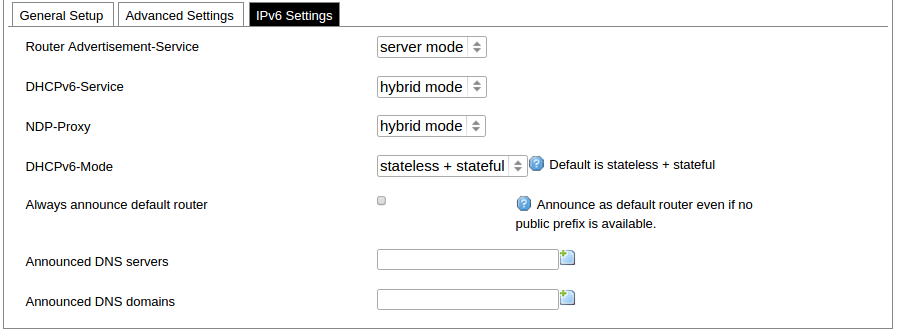
DHCP server IPv6 settings setup panel.
GSM
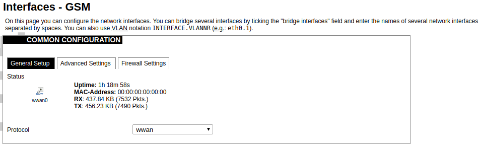
General Settings Information tab. Gives you the name of the physical GSM interface, and lets you choose the protocol (not recommended!).
Note: Make sure you won’t change the GSM interface's protocol, which is set by default to WWAN. Changing this parameter will lead to undefined GSM modem behaviour.
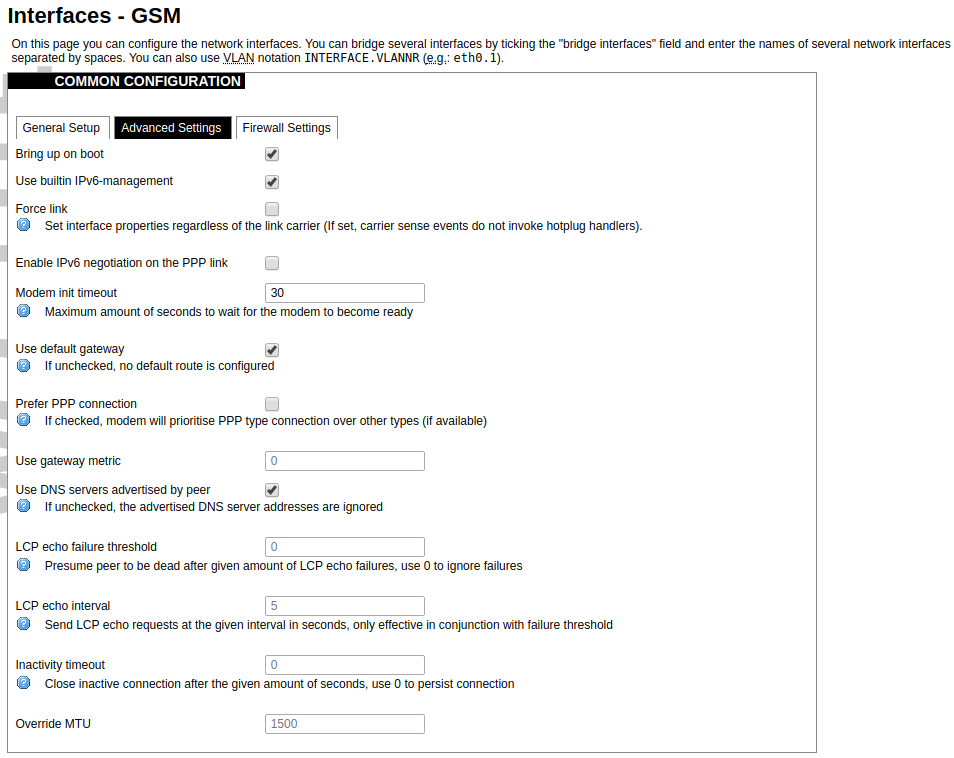
Advanced Settings tab enables users to configure advanced settings for mobile communication. It includes the following options:
Bring up on boot: Checkbox to start a GSM interface on startup;
Use built-in IPv6-management: Checkbox to select if the device is going to use its tools to manage IPv6 transport layer messages;
Force link: Specifies whether IP address, route, and gateway are assigned to the interface regardless of whether the link is active or only after the link has become active; when active, carrier sense events do not invoke hotplug handlers;
IPv6 support: The user can select if IPv6 support is handled automatically, manually or disabled altogether;
Modem init timeout: Maximum amount of seconds before the device gives up on finishing initialization;
Use default gateway: Uses the default gateway obtained through DHCP. If left unchecked, no default route is configured;
Prefer PPP connection: If, the modem, supports PPP and any other communication protocol (e.g. QMI, RNDIS etc.), prioritize PPP type connection;
Use gateway metric: The WAN configuration by default generates a routing table entry. In this field, you can alter the metric of that entry. Higher metric means higher priority;
Use DNS servers advertised by peer: Uses DNS servers obtained from DHCP. If left unchecked, the advertised DNS server addresses are ignored;
LCP echo failure threshold: LCP (link control protocol) is a part of PPP (Point-to-Point Protocol) and helps to determine the quality of data transmission. If enough failures happen, LCP presumes the link to be dead. 0 disables failure count checking;
LCP echo interval: Determines the period of LCP echo requests. Only effective if the LCP echo failure threshold is more than zero;
Inactivity timeout: Station inactivity limit in seconds: if a station does not send anything, the connection will be dropped. A value of 0 can be used to persist the connection.
Override MTU: Set custom MTU to GSM interface.
Note: If the modem uses QMI connection protocol and the user hasn’t defined a custom MTU setting, the MTU on the interface will be set to the operator’s defined MTU value.
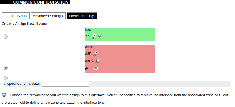
GSM configuration ends with firewall settings. A user can assign an already-defined firewall zone or create a new one.
Wireless
The wireless network interface parameters and configuration are described in this section.

Configured interfaces for the physical radio device.
Channel: Specifies the wireless channel to use.
Bitrate: Specifies transfer rate in Mbit/s.
SSID: The broadcasted service set identifier of the wireless network.
Mode: Select the operation mode of the wireless network interface controller.
BSSID: The basic service set identification of the network, only applicable in ad-hoc or STA mode.
Encryption: Wireless encryption method.

List of associated wireless stations.
The Device Configuration section covers the physical settings of the radio hardware such as channel, transmit power or antenna selection which are shared among all defined wireless networks (if the radio hardware is multi-SSID capable). Network settings like encryption or operation mode are grouped in the Interface Configuration.
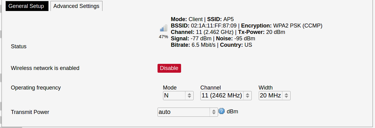
General device settings.
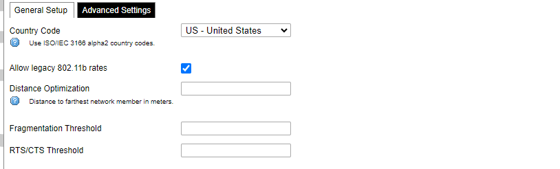
Advanced device settings.
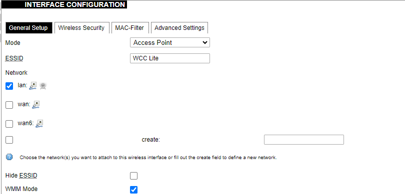
General interface settings.
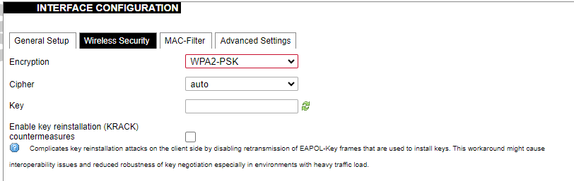
Wireless security interface settings.
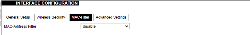
MAC-Filter settings.
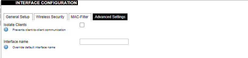
Advanced interface settings.
DHCP and DNS
DHCP server and DNS forward for NAT firewalls are described in this section.
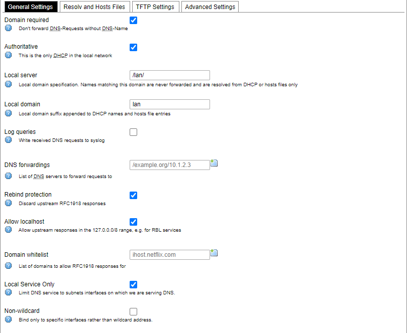
General DHCP settings.
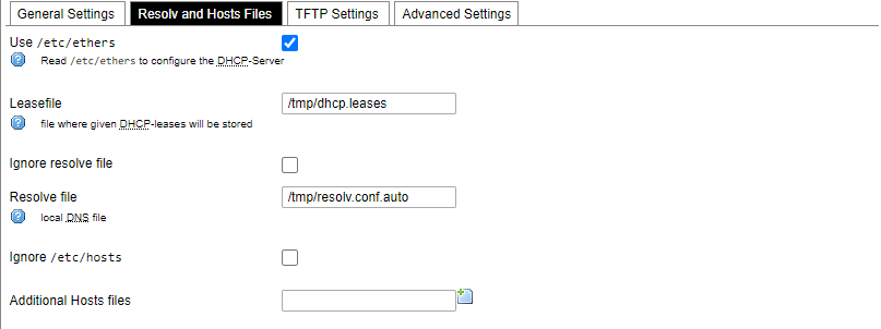
Resolve and host file settings.
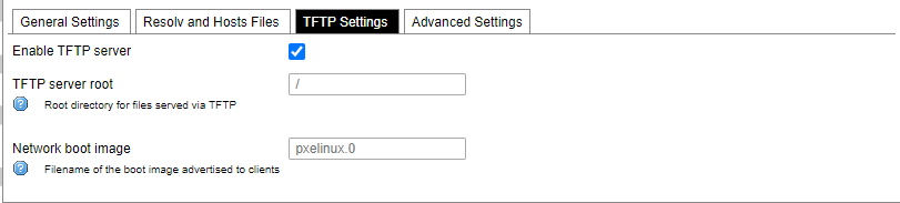
TFTP server settings.
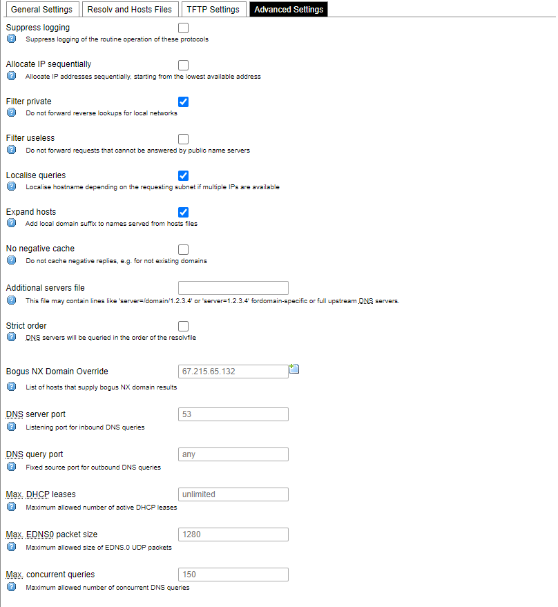
Advanced settings.
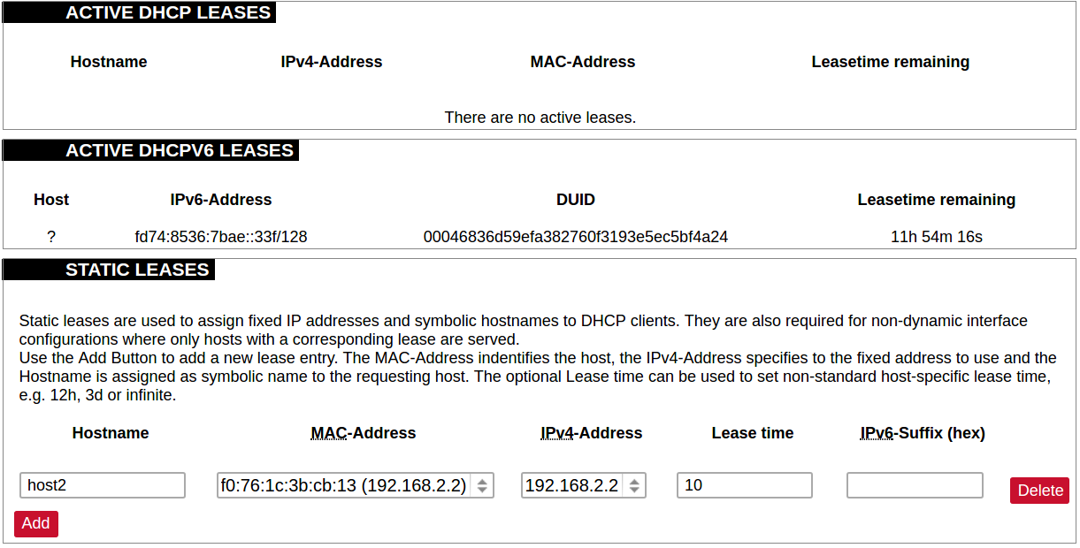
List of active DHCP and static leases. It is also possible to assign fixed IP addresses to hosts on the network, based on their MAC (hardware) address.
Hostnames
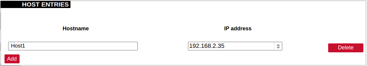
List of existing host names. Addition or deletion is allowed for the user.
Static routes
Routes specify over which interface and gateway a certain host or network can be reached.
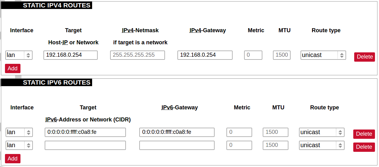
Current IPv4 and IPv6 static routes configuration.
Interface: Let to choose for which interface static route is created.
Target: Defines target host IP or network.
IPv4 Netmask: Defines netmask if the target is a network.
IPv4/IPv6 Gateway: Defines IPv4 or IPv6 gateway.
Metric: Specifies the route metric to use for the route.
MTU: Maximum Transmit/Receive Unit, in bytes.
Route type: All incoming packets can be: accepted, rejected, or dropped.
Diagnostics
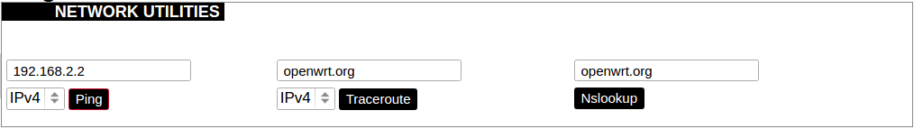
Diagnostics tools which can be used to diagnose some of the networking problems: ping, traceroute and nslookup.
Firewall
This subsection is divided into four categories: general settings, port forwards, traffic rules and custom rules.
General settings
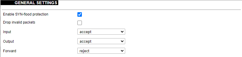
General firewall settings can be changed in the General Settings screen. These settings are defined as follows:
Input: All incoming packets can be: accepted, rejected, or dropped.
Output: All outgoing packets can be: accepted, rejected, or dropped.
Forward: All packets being sent to another device can be: accepted, rejected, or dropped.
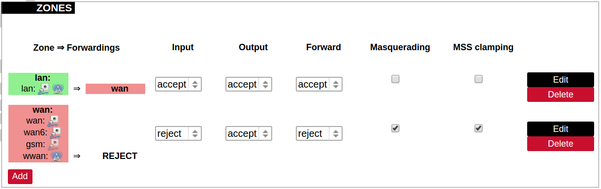
Additional zones for the firewall can be created, edited or deleted.
Zone => Forwardings: Defines zones and their traffic flow.
Input: All incoming packets can be: accepted, rejected, or dropped.
Output: All outgoing packets can be: accepted, rejected, or dropped.
Forward: All packets being sent to another device can be: accepted, rejected, or dropped.
Masquerading: Allows one or more devices in a zone network without assigned IP addresses to communicate with the Internet.
MSS clamping: Change the maximum segment size (MSS) of all TCP connections passing through this zone with MTU lower than the Ethernet default of 1500.
Additional actions can be performed with zones: add, edit, delete.
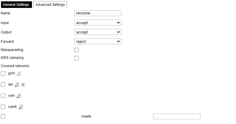
Common properties of newly created or edited zones can be edited in this panel. The input and output options set the default policies for traffic entering and leaving this zone while the forward option describes the policy for forwarded traffic between different networks within the zone. Covered networks specify which available networks are members of this zone.
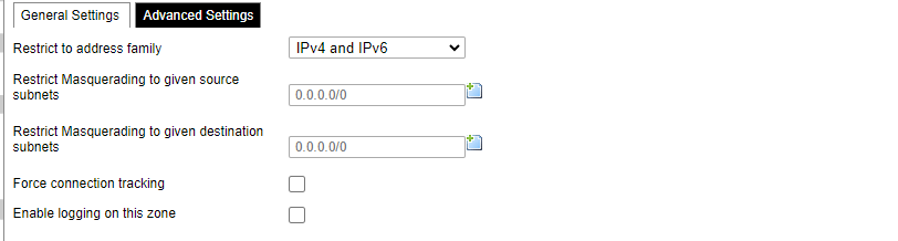
Advanced settings of newly created or edited zones. Restrict to address family option defines to what IP families the zone belongs to IPv4, IPv6 or both. Restrict masquerading to given source/destination subnets defines one or more subnets for which the masquerading option is applied. Connection tracking and logging options enable additional information gathering on the zone.
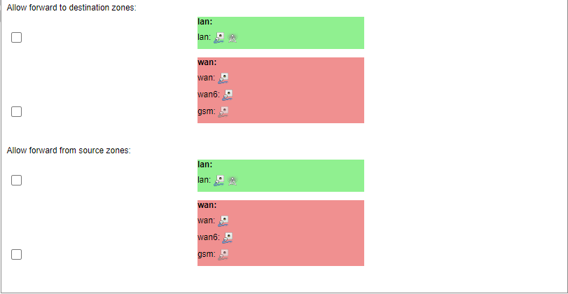
Controls the forwarding policies between new/edited zone and other zones. Destination zones cover forwarded traffic originating from the new/edited zone. Source zones match forwarded traffic from other zones targeted at the new/edited zone. The forwarding rule is unidirectional, e.g. a forward from LAN to WAN does not imply permission to forward from WAN to LAN as well.
Port forwards

Port forwarding allows remote computers on the Internet to connect to a specific computer or service within the private LAN. It is done in a way of routing network packets within a private network created by the device. Settings for the port forwarding of the device are defined as follows:
Name: The name of the port forwarding rule.
Match: Informs what port forward is matched to.
Forward to: Informs where the port is forwarded to.
Enable: Enable (checked) or disable port forward.
Sort: Allows to sort port forwarding.
The user can add, edit or delete port forwarding rules.
Traffic rules
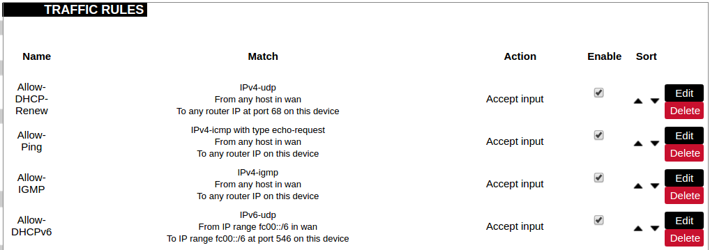
Traffic rules define policies for packets travelling between different zones.
Name: The name of the traffic rule.
Match: Informs what ICMP types are matched.
Action: Informs what action would be performed.
Enable: Enable (checked) or disable the rule.
Sort: Allows to sort rules.
The user can add, edit or delete traffic rules. Every rule can be defined by these options: name, restrict to address family, protocol, match ICMP type, source and destination zones, source MAC, IP addresses and port, destination IP address and port, action and extra arguments, month and weekdays for which rule will apply, start/stop dates and times, time in UTC.
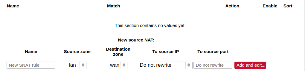
Source NAT is a specific form of masquerading which allows fine-grained control over the source IP used for outgoing traffic, for example, to map multiple WAN addresses to internal subnets.
The user can add, edit or delete source NAT rules. For every rule can be defined these options: name, protocol, source and destination zones, source, destination, SNAT IP addresses, ports, extra arguments, month and weekdays for which rule will apply, start/stop dates and times, time in UTC.
Custom rules

Custom rules allow the execution of arbitrary iptables commands which are not otherwise covered by the firewall framework. The commands are executed after each firewall restart, right after the default ruleset has been loaded.
GSM
Gsm settings
Note: If you have a WCC Lite without a modem, the GSM tab will still be visible, but these changes won't affect anything.
Note: From FW version 1.9.1 Pinger is disabled by default.
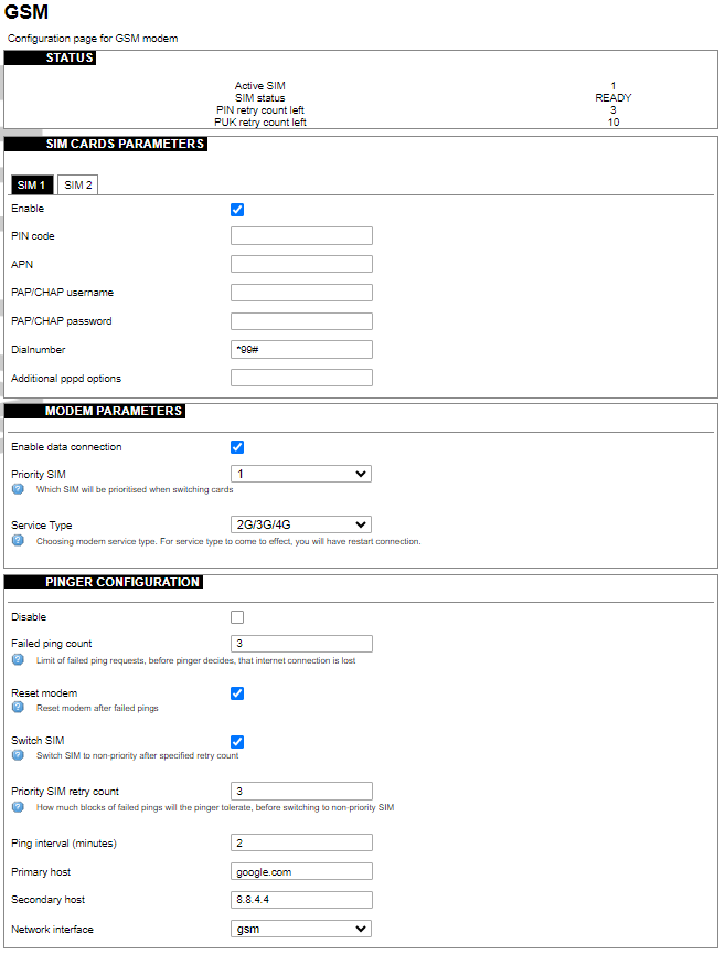
SIM cards parameters
Parameters for SIM card. If a single SIM modem is used, there won’t be ”SIM 1” and ”SIM 2” tabs.
Enable: Enable or disable this SIM card.
PIN code: PIN code to use on that SIM card.
APN: APN to use on that SIM car.
PAP/CHAP username: Username (optional).
PAP/CHAP password: Password (optional).
Modem parameters
Enable data connection: Enable or disable data connection through a GSM modem.
Priority SIM: Primary SIM card (if Dual SIM modem is used). Mainly used for pinger configuration.
Service Type: Which radio access technology will be used when connecting to the GSM network. Each modem has different available preset RAT options, that can be selected in the drop-down menu.
Pinger configuration
Pinger is a service which pings defined hosts to check internet connection. If both of these hosts are unreachable pinger will wait and restart the modem (or switch SIM card, if Dual-SIM modem is installed in WCC Lite)
Disable: Disable pinger functionality.
Failed ping count: Limit of failed ping requests, before the pinger decides that the internet connection is lost.
Reset modem: If checked, pinger resets the gsm modem after ”Failed ping count”.
Switch SIM: If checked, pinger switches SIM to non-priority after ”Priority SIM retry count”. If an internet connection is not available with a non-priority SIM as well, the pinger switches back to a priority SIM after one failed ping attempt.
Priority SIM retry count: How many blocks of failed pings will the pinger tolerate, before switching to non-priority SIM.
Ping interval (minutes): Interval between ping requests.
Primary host: The host that will be pinged first.
Secondary host: The host that will be pinged second, if the primary host fails.
Network interface: GSM network interface name.
GSM Pinger is used to detect the status of network connections via cellular networks. This status is written to file (/var/run/board/internet-status) and can be configured to be sent to SCADAs. If the pinger is disabled, the status is always set equal to zero and should not be trusted to represent internet status. Additionally, this status is reflected in the ”Status”-> “GSM Status” window.
This is Pinger functionality described step by step:
• Pinger will ping the primary host every 2 minutes.
• If the primary host fails, the pinger redirects to the secondary host immediately.
• If either the primary or secondary host is responding to ping requests, the pinger will continue testing the connection with every ”Ping interval (minutes)” parameter and no further action is taken.
• If both primary and secondary hosts are unreachable, the pinger will start pinging these hosts every ”Ping interval (minutes) / 2” minute for ”Failed ping count” times.
• If hosts are still unreachable, the pinger will try to switch SIM and restart the modem (if corresponding parameters are set) or will restart immediately if a single SIM modem is used.
• SIM card is switched to non-priority SIM after ”Priority SIM retry count” failed modem restarts with priority SIM. If a non-priority SIM fails, it is switched to a priority SIM in the next pinger action.
Dual SIM start procedure
The table below shows, which card is expected on boot when a selection is made between Enable/Disable SIM cards and Primary card.
| SIM 1 Enabled | SIM 2 Enabled | Priority SIM | SIM on boot |
| X | 1 | 1 | |
| X | 2 | 1 | |
| X | 1 | 2 | |
| X | 2 | 2 | |
| X | X | 1 | 1 |
| X | X | 2 | 2 |
| 1 | Undefined | ||
| 2 | Undefined |
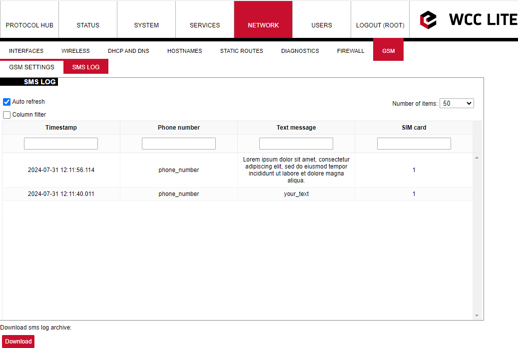
SMS Log
SMS logging is available from firmware version 1.9.1
Here the user can find all the messages that were sent to the device. It shows the time that the message was received, the sender's phone number and the text sent. The SIM card column shows to which SIM card (1 or 2) was the message sent.
Layer 2 Tunneling Protocol
In computer networking, Layer 2 Tunneling Protocol (L2TP) is a tunnelling protocol used to support virtual private networks (VPNs) or as part of the delivery of services by ISPs. It does not provide any encryption or confidentiality by itself. Rather, it relies on an encryption protocol that it passes within the tunnel to provide privacy.
Description
The entire L2TP packet, including payload and L2TP header, is sent within a User Datagram Protocol (UDP) datagram. It is common to carry PPP sessions within an L2TP tunnel. L2TP does not provide confidentiality or strong authentication by itself. IPsec is often used to secure L2TP packets by providing confidentiality, authentication and integrity. The combination of these two protocols is generally known as L2TP/IPsec (discussed below). The two endpoints of an L2TP tunnel are called the LAC (L2TP Access Concentrator) and the LNS (L2TP Network Server). The LNS waits for new tunnels. Once a tunnel is established, the network traffic between the peers is bidirectional. To be useful for networking, higher-level protocols are then run through the L2TP tunnel. To facilitate this, an L2TP session (or ’call’) is established within the tunnel for each higher-level protocol such as PPP. Either the LAC or LNS may initiate sessions. The traffic for each session is isolated by L2TP, so it is possible to set up multiple virtual networks across a single tunnel. MTU should be considered when implementing L2TP. The packets exchanged within an L2TP tunnel are categorized as either control packets or data packets. L2TP provides reliability features for the control packets, but no reliability for data packets. Reliability, if desired, must be provided by the nested protocols running within each session of the L2TP tunnel. L2TP allows the creation of a virtual private dialup network (VPDN) to connect a remote client to its corporate network by using a shared infrastructure, which could be the Internet or a service provider’s network.
Setting up the L2TP interface
To create an L2TP tunnel following steps are required:
1. Go to Network > Interfaces > Add new interface:
2. Enter the interface name and select L2TP protocol:

3. Enter the server name and authorization parameters:

4. Save and apply the new configuration. A new network interface will appear.
8.8 Users
Edit groups
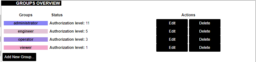
On this page, user groups can be edited, deleted or added.
Groups: name of the user group
Status: shows authorization level set to the specific user group. The higher the lever, the higher the authorization requirements.
Actions: edit or delete a user group
Add new group
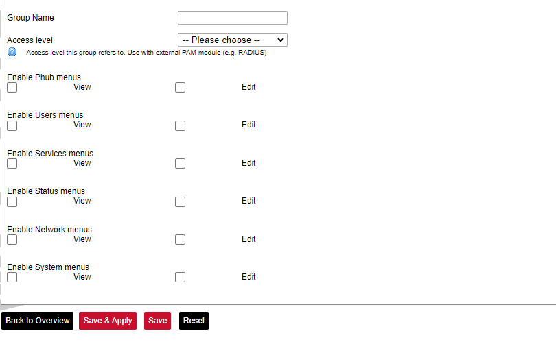
Configuration window for the new group. After the group name is determined, access level and permissions can be set.
Edit users
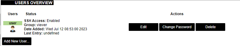
On the edit users window list of all the users is shown.
Users: user name
Status: shows if SSH access is enabled and which group the user belongs to.
Actions: edit, delete or change the password for the user
Add new user
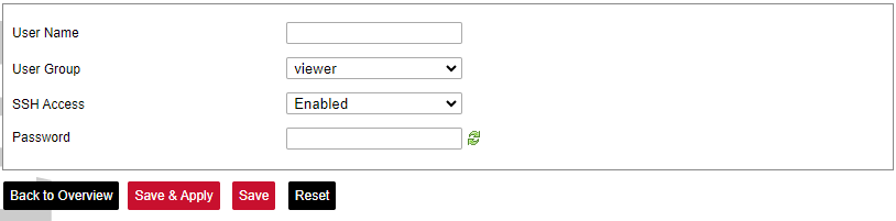
Configuration window for new users. To create a new user, a name and password should be created and user group and SSH access should be set.
Password

Changes the password of the device.
8.9 Logout

To log out of the device graphical user interface a logout button in the interface’s upper right corner should be pressed. A user is automatically disconnected after ten minutes of inactivity. This ensures that the device would not be suspected of any deliberate damage made by unauthorized access.