18 Excel Configuration
Protocol HUB uses the configuration in excel file format. Each sheet represents a specific part of the configuration: Devices contain device lists and protocol-related configurations. Signals contain a list of signals and their options. First-line on each sheet is a header row that contains the parameter name for each column. Header order determines parameter names for each following row. Every line after the header is a new entry. An empty row is interpreted as the end of the sheet. Any rows after empty row are discarded.
- 18.1 Devices sheet
- 18.2 Optional parameters for signals
- 18.3 Mathematical functions
- 18.4 Uploading configuration
- 18.5 Virtual device
18.1 Devices sheet
Devices sheet contains all devices to be configured on the gateway. Each row represents one device and its settings. Following options are required for each device:
- name - Name of the device. Used for representation only.
- description - A short description of the device. Used for representation only.
- device_alias - A unique short name for the device. It is used for linking signals to a device.
An alias can only contain alphanumeric characters and dashes ( - and _ ). The alias must be unique for each device.
- protocol - Protocol type to use on the device. The exact values of protocols are written in every protocol documentation. Please look into the range of supported protocols:
IEC 61850 MMS:
– IEC 61850 Client (since FW 1.5.0)
– IEC 61850 Server (since FW 1.5.0)
IEC 60870-5:
– IEC 60870-5-101 master
– IEC 60870-5-101 slave
– IEC 60870-5-103 master
– IEC 60870-5-104 master
- IEC 60870-5-104 slave
DNP 3.0 Serial/LAN/WAN:
- DNP3 Master
– DNP3 Slave
Modbus Serial/TCP:
- Modbus RTU/ASCII
– Modbus TCP
Metering protocols:
- DLMS/COSEM (since FW 1.3.0)
– IEC 62056-21 (since FW 1.2.13)
– MBus Serial
– MBus TCP
– Elgama (Meters based on IEC 62056-21 / 31 protocols)
Industrial IOT protocols:
- MQTT
- RESTful API
Specific protocols:
– Aurora (ABB PV inverters protocol)
– PowerOne (ABB PV inverters protocol)
– SMA Net (SMA PV inverters protocol)
– Kaco (Kaco PV inverters protocol)
– Ginlong (Ginlong PV inverters protocol)
– Solplus (Solutronic AG PV inverters protocol)
– ComLynx (Danfoss PV inverters protocol)
– Delta (Delta PV inverters protocol)
– Windlog (Wind sensors from RainWise Inc.)
– Vestas ( Wind turbines protocol)
– Internal data
– VBus.
Although device name rules aren’t strictly enforced, it is highly advised to give a unique name to every new device. Identical device names might introduce confusion while searching for signals in the Imported Signals tab.
Optional settings
- enable - Flag to enable or disable a device on the system. Can contain values 0 or 1.
- event_history_size - Maximum number of signal events to save on device for later review. Older records will be erased. This feature is only available on cloud firmware.
Serial port settings
Required for any protocol that uses serial line communication.
- device - Serial port for communication (PORT1/PORT2)
- baudrate - Serial port speed. Valid values: 300; 600; 1200; 2400; 4800; 9600; 19200; 38400; 57600; 115200
- databits - Number of data bits (6-9)
-
stopbits - Number of stop bits (1-2)
-
parity - Parity mode (none/even/odd)
-
flowcontrol - Flow control method (none/hardware/software)
TCP/IP settings
Settings for any protocol that uses communication over TCP/IP. Note that all TLS certificates and keys are stored in a single folder therefore only the name and not the path should be filled in respective fields.
TLS fields are only supported for IEC 61850 Client and Server, IEC-60870-5-104 Slave, and DNP3 Master and Slave, MQTT.
- ip - IP address for a master protocol to connect to;
- bind_address - one of the local IP addresses to bind the server to. Connections through other network devices will be ignored;
- host - space-separated host IP addresses of master devices;
- port - TCP port to listen for incoming connections;
- tls_local_certificate - the name of local TLS certificate;
- tls_peer_certificate - the name of a certificate authority (CA) TLS certificate;
- tls_private_key - the name of a private key for making TLS connections.
18.2 Optional parameters for signals
The signals sheet contains all signals linked to devices. Each signal is defined in a single row. The Signal list can be split into multiple sheets. Each sheet name may start as Signals.
Required attributes
These attributes are mandatory for every configured signal. Every Excel configuration should have specified them in the first row of the Signals sheet:
-
signal_name - Name of the signal. Used for representation only.
-
device_alias - Alias of a device defined in the Devices sheet. A signal is linked to a matching device.
-
signal_alias - A unique short name for the signal. It is used for linking signals to other signals. The alias can only contain alphanumeric characters and dashes ( - and _ ). The device and signal alias combination must be unique.
Optional attributes
Optional attributes are required depending on the protocol in use and they can be used to extend protocol functionality:
-
source_device_alias - Alias of a source device defined in the Devices sheet. If a user intends to use several signals and combine them via mathematical or logical function, every alias should be separated by a newline symbol (in the same cell). An operation used must also be defined in an operation column.
-
source_signal_alias - Alias of a source signal defined in the Signals sheet. If a user intends to use several signals and combine them via mathematical or logical function, every alias should be separated by a separator symbol (in the same cell). An operation used must also be defined in an operation column. Each
source_signal_aliasshould be posted in the same line as its respectivesource_device_alias. Aliases can only contain alphanumeric characters and dashes ( - and _ ). The device and signal alias combination must be unique. -
enable - Flag to enable or disable signal on the system. Can contain values 0 or 1.
-
tag_type - Tag type. Simple signals are polled from the device. Virtual signals are computed
internally.
-
units - Signal value measurements units.
-
multiply - Multiply the value by this number.
- add - Add this number to a value.
-
min_value - Minimum expected value. If the result is lower than this value, the overflow flag is raised.
-
max_value - Maximum expected value. If the result is higher than this value, the overflow flag is raised.
-
absolute_threshold - Absolute threshold level.
-
integral_threshold - Integral threshold level.
-
integral_threshold_interval_ms - Integral threshold addition interval in milliseconds.
-
threshold_units - Units used in threshold level fields (percent/real).
-
log - Maximum number of records for this tag to keep in events log.
-
suppression_values - Space-separated numeric values to be used in suppression.
-
suppression_time_ms - Suppression time in milliseconds.
-
operation - Mathematical or logical operation to be used for signals defined in source_signal_alias column which are separated using separators. Following mathematical operations for source signal values can be used: avg (average of all values), min (lowest value), max (highest value), median (median value), and sum (all values accumulated to a single number). An internal threshold is used to reduce value updates when the value doesn't change. Logical operations are intended for unsigned integers only.
-
bit_select - selecting an individual bit of an integer number; bit numeration starts from zero.
-
math_expression - a mathematical expression for master protocol monitor direction or slave command direction signals to be evaluated against. Explained in detail in Mathematical expression document.
- source_math_expression - a mathematical expression for master protocol command direction or slave monitor direction signals to be evaluated against. Explained in detail in Mathematical expression document.
Picture. Result of using an absolute threshold:
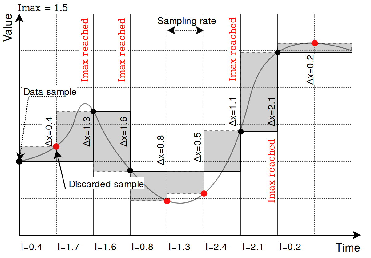
Picture. Result of using an integral threshold:

Signal recalculation operation priority
A value generated by some protocol usually has to be recalculated in one way or another. This might mean changing the value of an argument as well as adding flags needed for other protocols to correctly interpret results. As recalculation is a sequential process, some actions are done before others. The sequence of operations done to a value is as follows:
-
Edition of attributes. Attributes for further interpretation are added. This might, for example, include a flag to show that a signal resembles an answer to a command;
-
Mathematical calculations. multiply, add, bit_select, and math_expression columns are evaluated here;
-
Usage of last value. The decision if last value for a signal should be used if a new value of a signal is not a number (NaN) or contains a non-topical (NT) flag;
-
Limiting of values. If a value exceeds a lower or higher configured limit, the value is approximated not be lower (or higher) than the limit. An additional overflow (OV) flag is added as frequently used in IEC-60870-5 protocols;
-
Suppression of values. As electrical circuits can be noisy, protocols may generate multiple values in a short amount of time. What is more, some values are considered as intermediaries and ideally should not be sent to SCADA unless they stay in the same state for some amount of time. suppression_values and suppression_time_ms are used to configure this functionality;
-
Threshold checking. If a new signal doesn’t cross a threshold target value, the value is suppressed and not used in further stages. absolute_threshold, integral_threshold, integral_threshold_interval, threshold_units columns are used to configure this functionality.
Not all of the elements in this sequence have to be configured, missing operations are skipped and values are fed to a further stage of signal recalculation.
number_type field
This field is required for some protocols to determine a method to retrieve a signal value from hexadecimal form. Available values:
• FLOAT - 32-bit single precision floating point value according to IEEE 754 standard
• DOUBLE - 64-bit double precision floating point value according to IEEE 754 standard
• DIGITAL - 1-bit boolean value
• UNSIGNED8 - 8-bit unsigned integer (0 - 255)
• SIGNED8 - 8-bit signed integer (-128 - 127)
• UNSIGNED16 - 16-bit unsigned integer (0 - 65535)
• SIGNED16 - 16-bit signed integer (-32768 - 32767)
• UNSIGNED32 - 32-bit unsigned integer (0 - 4294967295)
• SIGNED32 - 32-bit signed integer (-2147483648 - 2147483647)
• UNSIGNED64 - 64-bit unsigned integer (0 - 18446744073709551615)
• SIGNED64 - 64-bit signed integer (-9223372036854775808 - 9223372036854775807)
Number conversion uses big-endian byte order by default. Converted data will be invalid if the byte order on the connected device side is different. In such a case, byte swap operations can be used. Adding swap prefixes to number types will set different byte orders while converting values. Following swap operations are available:
-
SW8 - Swap every pair of bytes (8 bits) (e.g., 0xAABBCCDD is translated to 0xBBAADDCC);
-
SW16 - Swap every pair of words (16 bits) (e.g., 0xAABBCCDD is translated to 0xCCDDAABB);
-
SW32 - Swap every pair of two words (32 bits) (e.g., 0x1122334455667788 is translated to 0x5566778811223344);
Table. Example of using different swapping functions:
| Address | 0 | 1 | 2 | 3 | 4 | 5 | 6 | 7 |
| Original number | Byte 0 | Byte 1 | Byte 2 | Byte 3 | Byte 4 | Byte 5 | Byte 6 | Byte 7 |
| SW8 | Byte 1 | Byte 0 | Byte 3 | Byte 2 | Byte 5 | Byte 4 | Byte 7 | Byte 6 |
| SW16 | Byte 4 | Byte 5 | Byte 6 | Byte 7 | Byte 1 | Byte 6 | Byte 4 | Byte 5 |
| SW32 | Byte 4 | Byte 5 | Byte 6 | Byte 7 | Byte 0 | Byte 1 | Byte 2 | Byte 3 |
| SW8.SW16 | Byte 3 | Byte 2 | Byte 1 | Byte 0 | Byte 7 | Byte 6 | Byte 5 | Byte 4 |
| SW8.SW32 | Byte 5 | Byte 4 | Byte 7 | Byte 6 | Byte 1 | Byte 0 | Byte 3 | Byte 2 |
| SW8.SW16.SW32 | Byte 7 | Byte 6 | Byte 5 | Byte 4 | Byte 3 | Byte 2 | Byte 1 |
Byte 0 |
Where Byte x, means bit x position in the byte.
Add a dot-separated prefix to the number format to use byte swapping. Multiple swap operations can be used simultaneously. For example, use SW8.SW16.SIGNED32 it to correctly parse a 32-bit signed integer in a little-endian format. Table shows in detail how bytes, words, or double-words can be swapped and how swapping functions can be combined to make different swapping patterns. The table shows how byte swap is done for 64-bit (8-byte) numbers. It doesn’t matter if it is an unsigned/signed integer or double, byte swapping is considered a bit-level operation. If a number is shorter than 64 bits, the same logic applies, the only difference is the unavailability of some swapping operations (SW32 for 32-bit and smaller numbers). Using such an unavailable operation might lead to undefined behavior.
Linking signals
Signals can be linked together to achieve data transfer between several protocols. If a signal source is defined, all output from that source will be routed to the input of the target signal. This way events polled from a Modbus device (e.g., Modbus, IEC 60870-5, etc.) can be delivered to an external station over a different protocol. A signal source is required if a signal is created on a slave protocol configuration to link events between protocols.
Example 1:
To read a coil state from a Modbus device and transfer it to IEC 60870-5-104 station, the following steps may be taken:
-
Create a Modbus master configuration in the Devices sheet.
-
Create an IEC 60870-5-104 slave configuration in the Devices sheet.
-
Create a signal on the master device to read coil status (function 1).
-
Create a signal on the slave device with a single point type (data_type = 1).
-
Set source_device_alias and source_signal_alias fields on slave device signal to match device_alias and signal_alias on master device’s coil signal.
Example 2
To write a coil state to a Modbus device on a command from IEC 60870-5-104 station, the following steps may be taken:
-
Follow steps 1-3 from example 1.
-
Create a signal on the slave device with a single command type (data_type = 45).
-
Set source_device_alias and source_signal_alias fields on the master configuration coil signal to match device_alias and signal_alias on the slave device’s command signal. Coil will be written to a value received by a command.
-
Set source_device_alias and source_signal_alias fields on the command signal to match device_alias and signal_alias on the master device’s coil signal. A command termination signal will be reported to the station on the coil write the result.
For additional information regarding the configuration of IEC 60870-5-101/103/104 protocols, please refer to ”IEC 60780-5-101/103/104 PID interoperability for WCC Lite devices”, accordingly.
Separators
These operators can be used when defining two or more values in a single cell. For example, source_signal_alias and source_device_alias from different signals have to be written in the same cell but separated by the separators listed below. This is useful when using the operation parameter when trying to do mathematical operations on more than one signal.
-
“ “
- (newline)
-
“;”
-
“,”
18.3 Mathematical functions
Signal value might require some recalculation or signal update prior to being sent. Understandably, existing columns in Excel configuration like multiply, add, bit_select might not be flexible enough. To overcome these limitations, symbolic mathematical expressions can be configured to do calculations automatically on every update of a signal.
Feature list:
- Optimized for speed
- High parsing performance
- if-then-else operator with lazy evaluation
- Default implementation with many features
-
25 predefined functions
-
18 predefined operators
-
-
Unit support
-
Use postfix operators as unit multipliers (3m -> 0.003)
-
Mathematical functions
Table. Supported mathematical functions:
| Name | Argument count | Explanation |
| sin | 1 |
sine function (rad) |
| cos | 1 |
cosine function (rad) |
| tan | 1 |
tangent function (rad) |
| asin | 1 |
arcus sine function (rad) |
| acos | 1 |
arcus cosine function (rad) |
| atan | 1 |
arcus tangent function (rad) |
|
sinh |
1 |
hyperbolic sine function |
| cosh | 1 |
hyperbolic cosine |
| tanh | 1 |
hyperbolic tangent function |
| asinh | 1 |
hyperbolic arcus sine function |
| acosh | 1 |
hyperbolic arcus tangent function |
| atanh | 1 |
hyperbolic arcus tangent function |
| log2 | 1 |
logarithm to the base 2 |
| log10 | 1 |
logarithm to the base 10 |
| log | 1 |
logarithm to base e (2.71828...) |
| ln | 1 |
logarithm to base e (2.71828...) |
| exp | 1 |
e raised to the power of x |
| sqrt | 1 |
square root of a value |
| sign | 1 |
sign function -1 if x<0; 1 if x>0 |
| rint | 1 |
round to nearest integer |
| abs | 1 |
absolute value |
| min | variable |
min of all arguments |
| max | variable |
max of all arguments |
| sum | variable |
sum of all arguments |
| avg | variable |
mean value of all arguments |
| floor | 1 |
round down to the nearest integer |
| mod | variable |
modulo operation |
It should be noted that trigonometric functions (excluding hyperbolic functions) only support arguments in radians. This means that arguments for this function have to be recalculated if angle is defined in degrees.
Value recalculation is only triggered on signal change of the preconfigured signal. That means that using other signals (via TagValue() call) does not trigger value update.
Some mathematical expression cannot be mathematically evaluated in some conditions, for example, square root cannot be found for negative numbers. As complex numbers are not supported, result is then equal to Not a Number (NaN). These results are marked with an invalid (IV) flag.
Binary operations
Table. Supported binary operators:
| Operator | Description | Priority |
|
= |
assignment |
-1 |
|
» |
right shift |
0 |
|
« |
left shift |
0 |
|
& |
bitwise and |
0 |
|
| |
bitwise or |
0 |
|
&& |
logical and |
1 |
|
|| |
logical or |
2 |
|
<= |
less or equal |
4 |
|
>= |
greater or equal |
4 |
|
!= |
not equal |
4 |
|
== |
equal |
4 |
| > |
greater than |
4 |
| < |
less than |
4 |
| + |
addition |
5 |
| - |
subtraction |
5 |
| * |
multiplication |
6 |
| / |
division |
6 |
|
^ |
raise x to the power of y |
7 |
Ternary operators can be used. This expression can be compared to the operator supported by C/C++ language (Table 39). Condition is written before a question (?) sign. If condition is true, result after question sign is selected. If condition is false, result after colon (:) is selected.
Ternary operations
Table. Supported ternary operators
| Operator | Description | Remarks |
|
?: |
if then else operator |
C++ style syntax |
Examples
Users can construct their own equation by using the aforementioned operators and functions. These examples can be seen in Table below.
Table. Example expressions
|
Expression |
Description |
|
value * 0.0001 |
Multiply the tag by a constant. |
|
value + TagValue(”tag/dev_alias/sig_alias/out”) |
Add value of tag/dev_alias/sig_alias/out to the current tag. |
|
sin(value) |
Return a predefined sine function value of the tag. |
|
(value>5)? 1: 0 |
If the value is greater than 5, the result should be equal to 1, otherwise - equal to 0 |
Variable called "value" is generated or updated on every signal change and represents the signals being configured. If another value from tag list is intended to be used, one should use TagValue() function to retrieve its last value.
The inner argument of TagValue() function has to described in a Redis topic structure of WCC Lite. That means that it has to be constructed in a certain way. Quotes should be used to feed the topic name value, otherwise expression evaluation will fail.
Every Redis topic name is constructed as tag/[device_alias]/[signal_alias]/[direction]. Prefix tag/ is always used before the rest of argument. device_alias and signal_alias represent columns in Excel configuration. Direction can have one of four possible values - rout, out, in, rin; all of which depend on the direction data is sent or acquired device-wise. For example, "out" keyword marks data sent out of WCC Lite device, whereas "in" direction represents data that WCC Lite is waiting to receive, for example, commands. Additional "r" before either direction means that data is raw, it is presented the way it was read by an individual protocol.
Signal mathematics
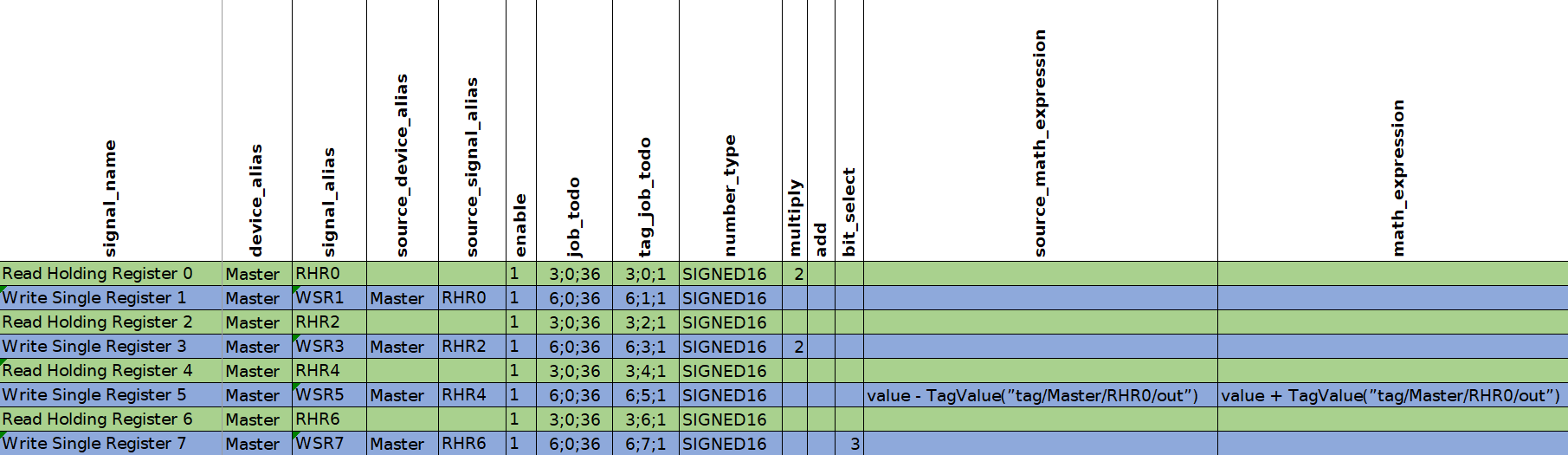
In this section you will be shown how "math_expression" and other mathematical functions can be used in case of common signals. You can download configuration to follow along here. Signals which we are concerned with in this section are highlighted in green color.
Let us analyze what mathematical functions are configured for the signals. For both second and third signals the same expression will be used: "value + TagValue(”tag/Master/RHR0/out”)". The only difference is that for the second signal scale function "add" was used.
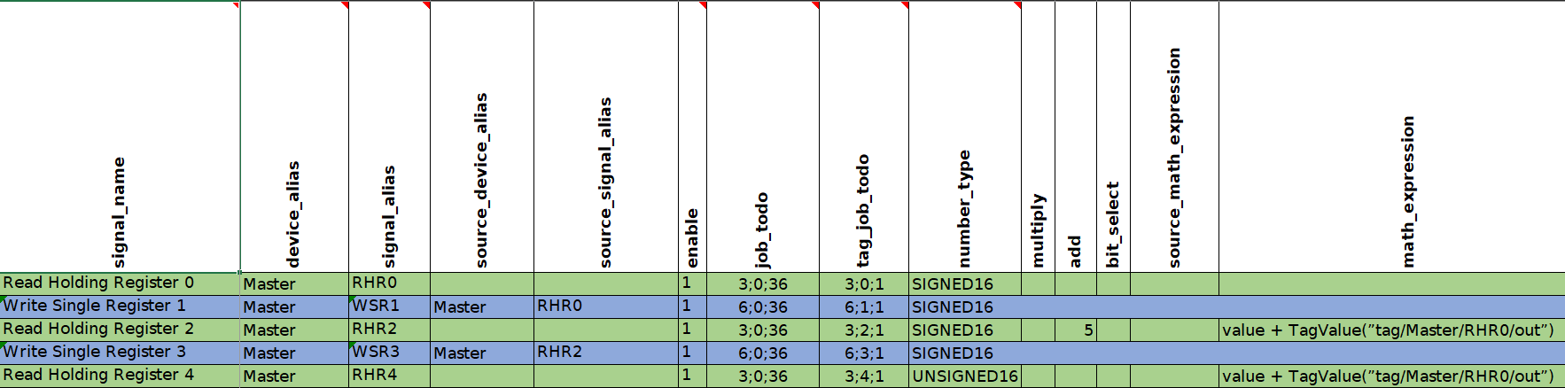
In this signal configuration the value of second signal is calculated by adding the current value of the second signal with the value of the first signal. Then the sum of two signals is going to be increased by 5. The third signal is going to be calculated in the same way except that 5 is not going to be added.
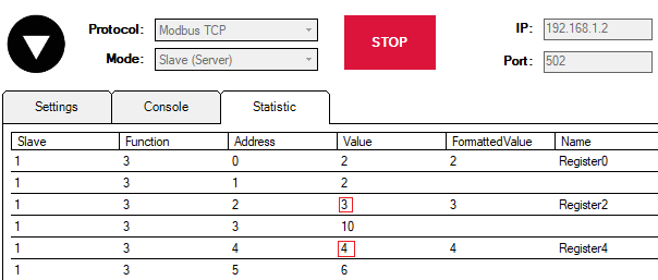
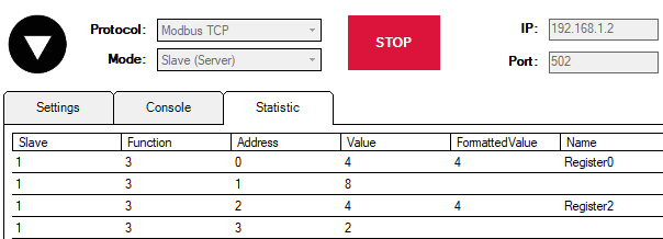
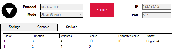
To see how it works let us start Modbus TCP Slave simulation in Vinci application. You can download the simulation here.
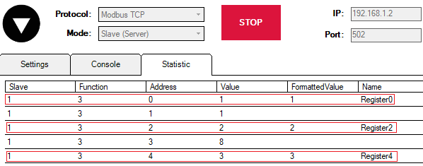
In the picture above you can see 6 registers. However our main focus is null, second and forth registers (Register0, Register2, Register4) since the first three signals of Modbus Master protocol (RHR0, RHR2 and RHR4) are reading the values of those registers (accordingly).
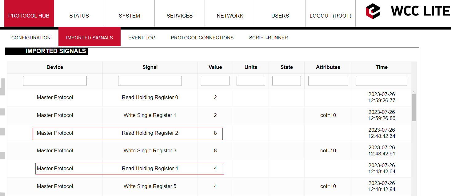
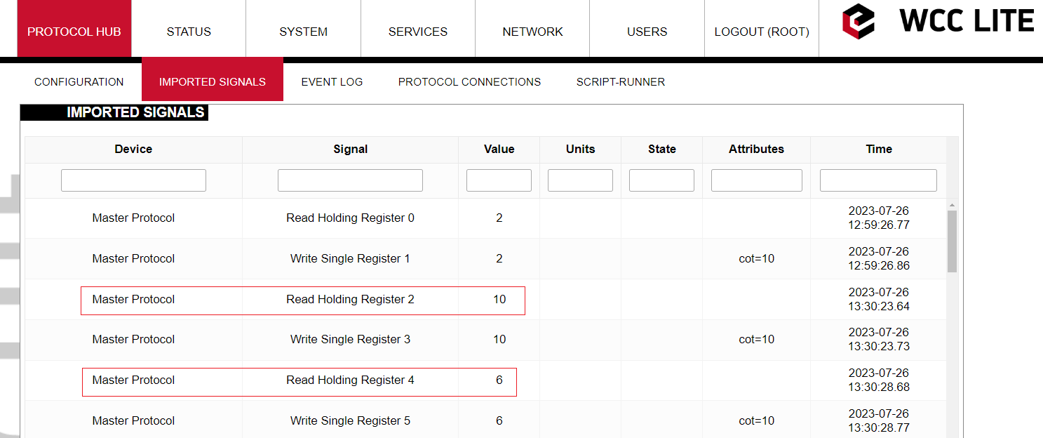
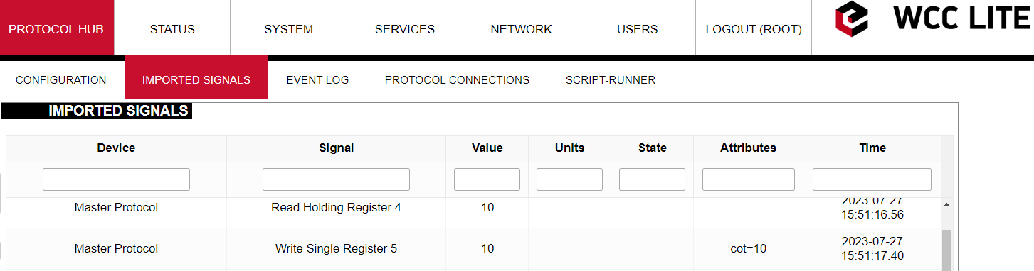
Let us go to WCC Lite web-interface to see how these signals are displayed there:
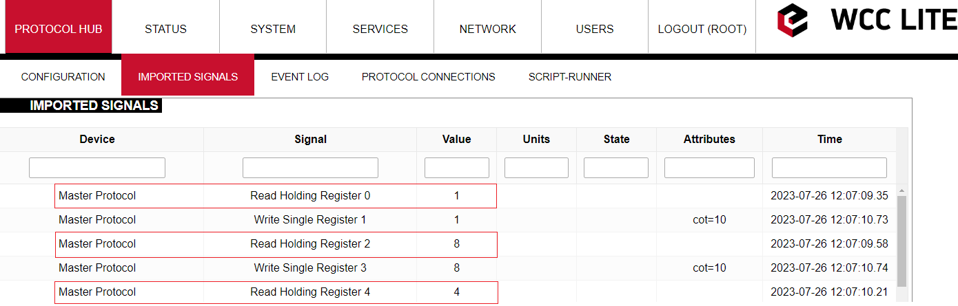
As we can see the values of third and fifth signals have been modified (RHR2 = 2+1+5 = 8; RHR3 = 3+1 = 4). However the values of the signals that are displayed in the web-interface are intermediate so to speak. All the math is done in the protocol sevices (Modbus TCP Master in this case). Then those values are transmitted to REDIS service. The values that are displayed in the web-interface are REDIS values. We are going to see why it is important in another example.
Now it was mentioned that the values of third and fifth signals depend on the value of the first one. Let us see what will happen if we change the value of the Register 0. To do so we need to return to VINCI application. Locate Register 0 and double click on it. A menu with the register parameters will appear.
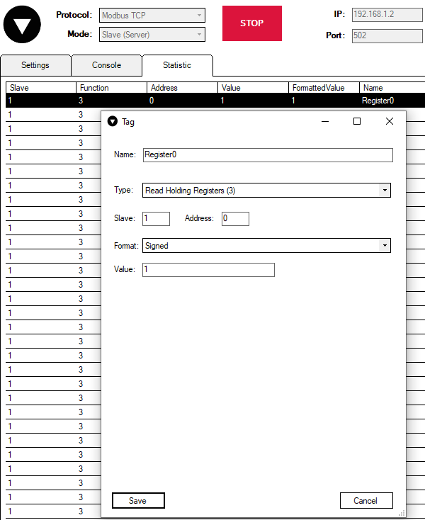
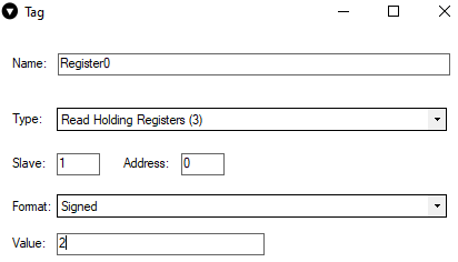
Now let us change the value of the register to 2:
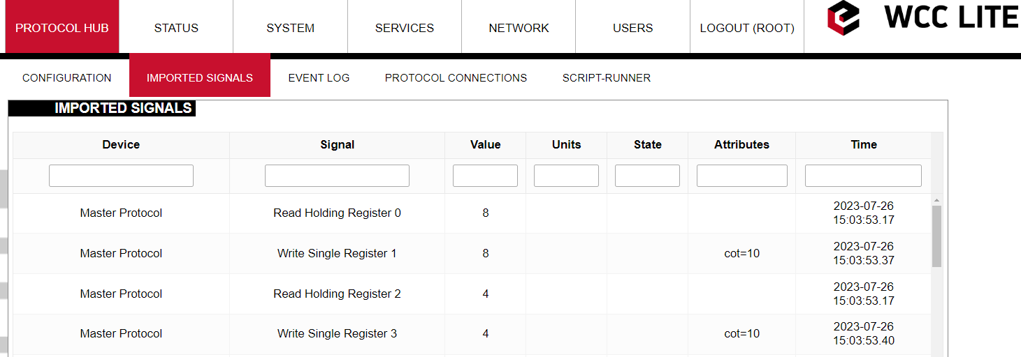
 Now it would be expected that the value of second and third signals would become 9 and 5 accordingly (RHR2 = 2+2+5 = 9; RHR3 = 3+2 = 5). However if one would check WCC Lite web-interface right after that, one could notice that second and third signals remained unchanged:
To explain this let us look again at the math expression of these signals. The equation (value + TagValue(”tag/Master/RHR0/out”)) consists of two operands "value" and "TagValue(”tag/Master/RHR0/out”)". Currently the system is designed in such a way that only if "value" operand has changed, only then there is going to be a change in a signal's value. So that if values of second and forth registers are changed (increased by one in this example) then the values of third and fifth signals are going to change taking into account the previous change in value of Register 0 (RHR2 = 2+3+5 = 10; RHR3 = 2+4 = 6).
Command mathematics
In this section you will be shown how "math_expression", and other mathematical functions can be used in case of command signals. You can download configuration to follow along here. Signals which we are concerned with in this section are highlighted in blue color.
Let us analyze what mathematical functions are configured for the signals.
First four signals are going to be used for scale function analysis. To see how it works let us start Modbus TCP Slave simulation in Vinci application. You can download the simulation here.
Let us go to WCC Lite web-interface to see how these signals are displayed there:
As one can notice the values displayed in Vinci application differ from values displayed in web-interface. To better understand the results let us see step by step how signals are modified.
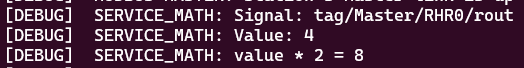
The first signal RHR0 reads the value of Register 0 which is equal to 4. After read operation the value is multiplied by two in the master protocol service. Then signal is transmitted to REDIS service. REDIS value is presented in web-interface. Then the same value 8 is written to Register 1 by sending WSR1 command signal. Finally the value of WSR1 signal is displayed in Vinci simulation.
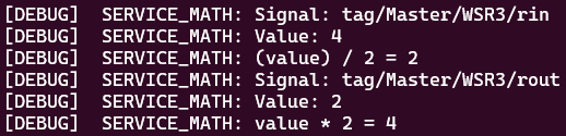
The third signal RHR2 behaves quite the same as the first RHR0 signal. It reads value of Register 2 and without performing any scaling operations transmits value to REDIS. It again can be seen in the web-interface. While still in REDIS service the value of Register 2 is passed to WSR3 signal. Then command signal WSR3 is transmitted back to Modbus Master protocol service where the value of the signal is scaled. One could expect that the value of the signal would be multiplied by two but it is divided by two. Then the value of 2 is displayed in Vinci Slave simulation. After changing the value of Register 3 WSR3 signal is sent back from Master Protocol service to REDIS. On its way the signal again passes signal scaling place where it is again multiplied by two. This is why we see in the web-interface that the value of forth signal WSR3 is 4.
All the moments when a signal passes a place where its value is scaled can be seen by turning on a debugger session. To do so one should connect to WCC Lite via Ubuntu terminal in Terminal application. Then Modbus Master protocol needs to be stopped by sending "/etc/init.d/modbus-master stop". Then Modbus Master protocol needs to be started again with -m flag (m for math) "modbus-master -d7 -m -c /etc/modbus-master/modbus-tcp.json".

If you scroll up after starting the session you will be able to find how both RHR0 and WSR3 signals are scaled after passing signal scaling place.
Why is it the case that the signal is divided instead of being multiplied by two? The answer to this question is that scaling factor depends on the direction of the signal. When RHR0 signal was travelling from Master Protocol to REDIS service and was passing the place where signals are scaled the signal was multiplied by scaling factor. On the other hand when WSR3 signal was travelling from REDIS service to Master Protocol and was passing the same signal scaling place the signal was divided by scaling factor.
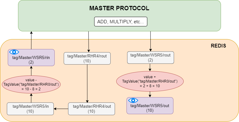
Now let us analyze how "math_expression" and "source_math_expression" are applied to WSR5 signal. To get a better insight let us look how signals are transmitted and transformed inside WCC Lite and when mathematical expressions are applied.
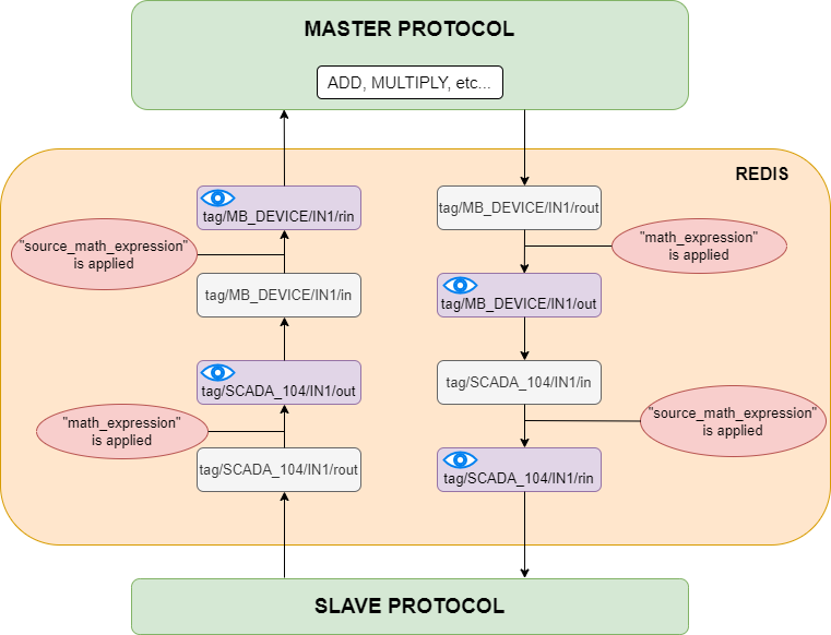
Let us analyze the diagram above. As we can see all basic mathematical operations (such as add, multiply, etc.) are performed inside a Master protocol service. When signals are transmitted between protocols they travel through REDIS service. The period of existence of a signal inside the REDIS service can be divided into four stages. They can be denoted by their endings, namely: "rout", "out", "in" and "rin". At "out" and "rin" stages signal values can be seen through certain interfaces that is why they are displayed in a purple color with blue eyes on them. At "out" stage a signal is displayed on WCC Lite web-interface, at "rin" stage signal value can be seen through Vinci application. As one could notice "math_expression" is applied before "out" stage and "source_math_expression" is performed before "rin" stage.
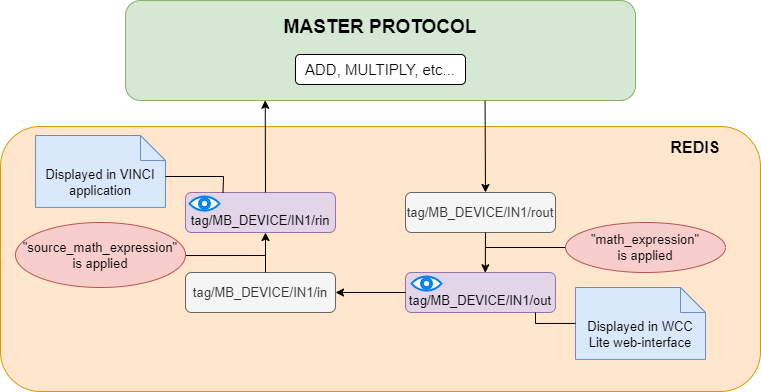
However in our particular example we did not configure any Slave device. In this situation signal transportation inside REDIS service can be depicted as following:
Let us return to our example and let us see what are the values of WSR5 signal in WCC Lite web-interface and Vinci Slave simulation.
The diagram below explains how these values were calculated.
Extra functions
Several functions are defined make tag operations possible:
TagValue(key)- returns last known value of tag identified by redis key;TagFlag(key)- returns 1 if tag flag exists. Name format is: ”key flag”. For example to check if tag is non topical, name would be ”tag/19xxxxxxx/x/x nt”;TagAttribute(key)- similar to TagFlag, but returns a numeric value of a tag attribute;TagTime(key)- returns UNIX timestamp in milliseconds of a last know tag value.
18.4 Uploading configuration
As of WCC Lite version v1.4.0, there are three separate ways to import the configuration: import an Excel file via the web interface, generate compressed configuration files and later upload them via the web interface; or generate compressed configuration files and upload them via utility application.
For WCC Lite versions v1.4.0, the name of the file is shown in Protocol Hub -->Configuration. Older versions only allow configuration files to be stored to a file called phub.xlsx and later downloaded with a custom-built name reflecting the date of a download. Upgrade process from older version to versions v1.4.0 and above when preserving configuration files automatically makes the necessary changes to enable this new functionality of WCC Lite.
If a user intends to downgrade the firmware to versions older than version v1.4.0 from newer versions, they must first download the configuration files and later reupload the configuration after finishing the upgrade process.
Importing an Excel file
Excel files can be imported without any external tools. This option can be used where there is no internet connection or only minor change has to be applied. This way of importing is not suitable for the validation of Excel configuration files.
Generating configuration is a resource-intensive task. It might take up to 10 minutes depending on configuration complexity
Supported types of an Excel configuration: .xlsx, .xlsm, .xltm, .xltx
To upload an Excel file, open Protocol Hub -->Configuration screen in Web interface, select Configuration file, and press Import configuration.
Generating .zip file
To accelerate the task of generating configuration a computer can be used. For this users should download the WCC Excel Utility application. Upon opening an application, the user should search for a field called Excel file which lets to choose an Excel file for which a conversion should be made. The output file should be filled out automatically, however, this value can be edited.
To make a conversion press Convert. If there are no errors found in the configuration, the output file should contain the generated configuration, otherwise, an error message is shown to a user.
This .zip file can be uploaded via the Web interface, using the same tools as used for import of an Excel file.
Uploading configuration remotely
As of WCC Lite version, v1.4.0 generated configuration files can be uploaded with a click of a button in the Excel Utility. There are four parameters (not counting the configuration file itself) that have to be filled in before starting upload:
-
Hostname: an IP address for the device to connect to. This field conforms to hostname rules, therefore, if an invalid value is selected, it is reset to default (192.168.1.1);
-
Port: a PORT number to which an SSH connection can be made; valid values fall into a range between 1 and 65535; if an invalid value is selected, it is reset to default (22);
-
Username: a username which is used to make an SSH connection; make sure this user has enough rights, preferably root;
-
Password: a password of a user used for establishing an SSH connection;
Configuration can only be uploaded if a port used for SSH connection is open for IP address filled in the hostname entry field. Please check WCC Lite firewall settings in case of connection failure.
To upload a configuration remotely, press Upload configuration. If no errors occur, you should finally be met with text output mentioning configuration has been applied. During the course of the upload process, the aforementioned button is disabled to prevent spanning multiple concurrent processes.
18.5 Virtual device
General
The virtual device is a device that you can use to calculate additional math or keep a counter. It doesn't bind to any protocol and only works when its math expression is used.
Virtual device functionality is only available since firmware version v1.6.3, of WCC Lite.
Configuring Virtual device
To configure WCC Lite to use the virtual device you must configure the device and signal sheets.
Virtual device parameters for Device tab:
| Parameter |
Type |
Description |
Required |
Default value (when not specified) |
Range |
|
|
Min |
Max |
|||||
| name | string | User-friendly device name | Yes | |||
| description | string | Description of the device | No | |||
| device_alias | string | Device alias to be used in the configuration | Yes | |||
| protocol | string | Selection of protocol | Yes | Virtual device |
||
Virtual device parameters for Signals tab:
| Parameter |
Type |
Description |
Required |
Default value (when not specified) |
Range |
|
|
Min |
Max |
|||||
| signal_name | string | User-friendly signal name | Yes |
|
|
|
| device_alias | string | Device alias from a Devices tab | Yes | |||
| signal_alias | string | Unique signal name to be used | Yes | |||
| math_expression | string |
Field to calculate specific math. You must enter the signal you want to use. |
Yes | |||
The only field that is a must to use the virtual device is the math_expression field. Here you need to enter the signal which you want to associate it with. Some examples of what it can do:
- Hold a specific tag value.
- Calculate a specific math function with many signals, that you can, later on, pass to another device.
- Add tag value to the current value, to create a counter.