Set debugging level
-c [ –config ] Config path
-r [ –raw ] Show raw telegram data
-f [ –frame ] Show frame data
-e [ –redis ] Show redis message
-R [ –readyfile ] Ready notification file
```
# 15 IEC 61850
# 15.1 Introduction
IEC 61850 is an international standard defining communication protocols for intelligent electronic devices at electrical substations. It is a part of the International Electrotechnical Commission’s (IEC) Technical Committee 57 reference architecture for electric power systems. The abstract data models defined in IEC 61850 can be mapped to a number of protocols. Possible mappings in the standard can be MMS (Manufacturing Message Specification), GOOSE (Generic Object Oriented Substation Event), SMV (Sampled Measured Values). These protocols can run over TCP/IP networks or substation LANs using high speed switched Ethernet to obtain the necessary response times below four milliseconds for protective relaying.
As of version v1.5.0, WCC Lite supports MMS type messaging. Logging and groups setting services are not supported.
# 15.2 IEC 61850 Server
WCC Lite can act as a IEC 61850 server to serve data to remote SCADA systems. For example, WCC Lite can be used to acquire data from various protocols (Modbus, IEC 60870-5-103, etc.), this data can be redirected and propagated further to a single or multiple IEC 61850 clients. IEC 61850 Server supports TCP and TLS connection types. TCP connection can be secured with password authentication.
#### Commands
WCC Lite **IEC 61850 Server** implementation defines four command types which are described by their control model:
- **Case 1**: Direct control with normal security (direct-operate);
- **Case 2**: SBO control with normal security (operate-once or operate-many);
- **Case 3**: Direct control with enhanced security (direct-operate);
- **Case 4**: SBO control with enhanced security (operate-once or operate-many).
Normal security commands are considered for execution if the command signal is found in Excel configuration. There aren’t any additional checks in command execution in any master protocol.
Enhanced security commands need feedback from master protocol to either to succeed or fail. If feedback is not received within **command\_ack\_timeout\_ms** timeframe, the command is considered as failed.
Command value attributes (e.g. stVal) must be updated separately (if they need to be updated).
When using SBO commands, select is not routed to master protocol and select logic is performed only in IEC 61850 Server protocol.
#### Configuring datapoints
To use IEC 61850 Server in WCC Lite, it has to be configured via an Excel configuration and data model must be uploaded. This configuration contains two Excel sheets where parameters have to befilled in - Devices and Signals.
##### IEC 61850 Server parameters for Devices tab
| **Parameter**
| **Type**
| **Description**
| **Required
| **Default value**
(when not specified)
| **Range**
|
| Min
| Max
|
| name
| string | User-friendly name for a device | Yes |
|
|
|
| description | string | Description of a device | No |
|
|
|
| device\_alias | string | Alphanumeric string to identify a device | Yes |
|
|
|
| enable | boolean | Enabling/disabling of a device | No | 1 | 0 | 1 |
| protocol | string | Protocol to be used | Yes |
| IEC 61850 Server |
| tls | string | Selecting if TLS should be used | No | 0
| 0 | 1 |
| bind\_address | string (IP address format) | IP address of and interface to use with server | No | 0.0.0.0 |
|
| host | string (IP address format) | IP address list of allowed IPs (separated with spaces)
| Yes |
|
|
|
| port | integer | TCP communication port
| Yes |
|
|
|
| tls\_local\_certificate | string | Local certificate for TLS connection
| Yes (for TLS) |
|
|
| tls\_peer\_certificate | string | Certificate authority file for TLS connection | Yes (for TLS) |
|
|
| tls\_private\_key | string | File consisting of private key for TLS connection | Yes (for TLS) |
|
|
|
| event\_history\_size | integer | Event log size | No |
|
|
|
| ied\_name | string | Name of an Intelligent Electronic Device | Yes |
|
|
|
| authorization | string | Authorization type | No |
| password |
| password | string | Authorization password for server device | Yes (if authorization is yes) |
|
|
|
| model\_filename | string | Filename of data model uploaded to WCC (with or without file extension) | Yes |
|
|
|
| edition | string | Which IEC61850 edition to use.
| No | 2 | 1,2, 2.1 |
| command\_ack\_timeout\_ms
| integer | Timeframe (ms) in which enhanced-security commands must be acknowledged
(Default: 3000)
| No | 3000 |
|
|
| report\_buffered\_size | integer | Report control blocks buffer size in bytes
(Default: 65536)
| No | 65536 |
|
|
| report\_unbuffered\_size | integer | Unbuffered report control blocks buffer size in bytes (Default: 65513)
| No | 65513 |
|
|
##### IEC 61850 Server parameters for Signals tab
| **Parameter**
| **Type**
| **Description**
| **Required
| **Default value**
(when not specified)
| **Range**
|
| Min
| Max
|
| signal\_name | string | User-friendly signal name | Yes |
|
|
|
| device\_alias | string | Device alias from a Devices tab | Yes |
|
|
|
| signal\_alias | string | Unique alphanumeric name of the signal to be used | Yes |
|
|
|
| enable | boolean | Enabling/disabling of an individual signal | No | 1 | 0 | 1 |
| log | boolean | Allow signal to be logged. If **log is 0 signal** will not be logged. If **log is more than 0** signal will be logged | No | 0 |
|
|
| number\_type | string | Number format type (BOOLEAN, FLOAT, INT16, etc.) | Yes |
|
|
|
| ld\_instance | string | Instance of a logical device | Yes |
|
|
|
| ln\_class | string | Logical node class type | Yes |
|
|
|
| ln\_instance | integer | Instance of a logical node | No |
|
|
|
| ln\_prefix | string | Prefix of logical node string | No |
|
|
|
| cdc | string | Common Data Class (CDC) name | Yes |
| SPS, DPS, INS, ENS, ACT, ACD, MV, CMV, SAV, SPC, DPC, INC, ENC, BSC, ISC, APC, BAC |
| data\_object | string | Name of data object in dataset | Yes |
|
|
|
| da\_value | string | Name of a data attribute value node | Yes |
|
|
|
| da\_time | string | Name of a data attribute time node | No |
|
|
|
| da\_quality | string | Name of a data attribute quality node | No |
|
|
|
| da\_fc | string | Functional constrain for data object | Yes |
| ST,MX, CO, SP |
| control\_model | string
| Model of output control
| No
| status-only | status-only,
direct-with-normal-security,
sbo-with-normal-security,
direct-with-enhanced-security, sbo-with-enhanced-security
|
#### Converting and uploading data model
To use IEC61850 Server protocol in WCC Lite, user must upload a data model in specific format (file extension .cfg). These data models can be converted from SCL files (.icd or .cid files). To convert a data model, the user must use WCC Excel Utility. There’s a separate tab for this operation as shown in picture below.
[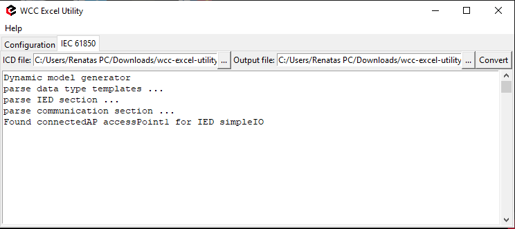](https://wiki.elseta.com/uploads/images/gallery/2020-09/image-1601465307717.png)
Converted file can be uploaded in WCC Lite web interface, Protocol Hub section. Current model can be also downloaded in the same page as shown in picture below.
[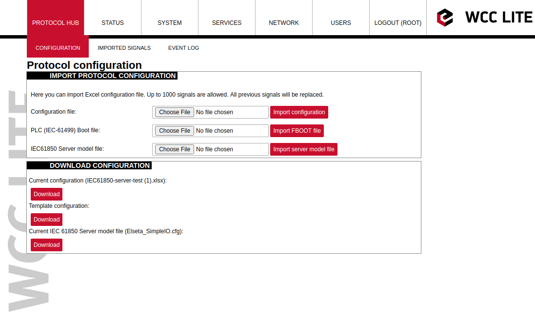](https://wiki.elseta.com/uploads/images/gallery/2020-09/image-1601465353342.png)
#### Debugging an IEC 61850 server application
If the configuration for IEC 61850 Server is set up, a handler for the protocol will start automatically. If the configuration is missing or contains errors, the protocol will not start. It is done intentionally to decrease unnecessary memory usage.
If IEC 61850 Server does not work properly (e.g. no communication between devices, data is corrupted, etc.), a user can launch a debug session from command line interface and find out why the link is not functioning properly.
To launch a debugging session, a user should stop `iec61850-server` process and run` iec61850-server` command with respective flags as you can see below:
```
iec61850-server
```
```iec61850-server
-h [--help] Show help message
-c [--config] arg Configuration file location
-V [--version] Show version
-d [--debug] arg Set Debug level
-r [--redis] Show Redis messages
-C [--commands] Show command messages
-R [--readyfile] arg Ready notification file
```
# 15.3 IEC 61850 Client
WCC Lite can be used as a master station to collect data from IEC 61850 compatible server devices such as protection relays. As relays require fast, secure and responsive interfaces, WCC Lite can be considered as a valid option. For additional security a user can use encrypted transmission (TLS) or set up a password.
As TCP (TLS) connection can encounter issues and break, automatic reconnection is implemented. After every failed reconnection attempt the fallback delay is doubled starting from 1 second up until 32 seconds. After that connection reestablishment will be attempted every 32 seconds until a successful connection.
#### Acquiring data via report control blocks
As per IEC 61850 standard, the report control block controls the procedures that are required for reporting values of data objects from one or more logical nodes to one client. Automatic reporting enables data servers (slave devices) to only send data on its (or its quality) change, thus saving network bandwith. Instances of report control blocks are configured in the server at configuration time.
Report control blocks send information that is defined in their respective datasets. Dataset is a set of data elements grouped to represent some data group. For example, it is a common practice to group measurements and events into different groups.
A server restricts access to an instance of a report control block to one client at a time. That client exclusively shall own that instance and shall receive reports from that instance of report control blocks. There are two classes of report control blocks defined, each with a slightly different behaviour:
- buffered-report-control-block (BRCB) - internal events (caused by trigger options data-change, quality-change, and data-update) issue immediate sending of reports or buffer the events (to some practical limit) for transmission, such that values of data object are not lost due to transport flow control constraints or loss of connection. BRCB provides the sequence-of-events (SOE) functionality;
- unbuffered-report-control-block (URCB) - internal events (caused by trigger options data-change, quality-change, and data-update) issue immediate sending of reports on a best efforts basis. If no association exists, or if the transport data flow is not fast enough to support it, events may be lost.
Buffered report control blocks are therefore useful to keep event data, for example, keeping the last known state of a relay switch where a loss of information might lead to a confusion and even financial losses. Unbuffered report control blocks are particularly useful for data which is useful only momentarily, e.g. measurements of voltages, current or power. This information can change frequently and old measurements might not reflect the real state of a substation.
To allow multiple clients to receive the same values of data object, multiple instances of the report control classes shall be made available.
Buffered report control blocks are usually configured to be used by a specific client implementing a well-defined functionality, for example, a SCADA master. The client may know the ObjectReference of the BRCB by configuration or by the use of a naming convention.
Parsing of report control blocks is based on types of Common Data Class (CDC). Some of these types can have more then one data point of interest. Table below shows what data attributes are supported from various Common Data Classes. To select which data attribute should be used a `da_value` column should be filled with a data attribute name. Common Data Classes consist of data attributes with different Functional Constraints therefore to get the status points of interest correctly the user must fill in a correct value in `da_fc` column.
IEC 61850 Client supported data attributes:
| Common Data Class | Function Constraint | Data attributes |
| SPS
DPS
INS
ENS
| ST | stVal |
| ACT | ST | general
phsA
phsB
phsC
neut
|
| ACD | ST | general
dirGeneral
phsA
dirPhsA
phsB
dirPhsB
phsC
dirPhsC
neut
dirNeut
|
| MV | MX | instMag
mag
|
| CMV | MX | instCVal
cVal
|
| SAV | MX | instMag |
| SPC
DPC
INC
ENC
| ST | stVal |
| BSC
ISC
| ST | valWTr |
| APC
BAC
| MX | mxVal |
Some of data attributes are structures themselves, for example, `mag` attribute is a struct that can hold integer or float values. To select a fitting attribute the user should extend `da_value` parameter with additional attributes, for example, if float magnitude value is to be selected from MV Common Data Class, `da_value` column should be filled with `mag.f` value; if the user intends `cVal` magnitude value in float format from CMV Common Data Class, `da_value` should be filled with `cVal.mag.f` value. See IEC 61850-7-3 for more information about Common Data Classes.
To ensure the integrity of configuration, WCC Lite has additional checks implemented at configuration time. If report control block (or its dataset) with a predefined ObjectReference doesn’t exist, it is considered that IEC 61850 Client has not been configured properly or configuration has been changed in either of IEC 61850 devices and cannot be matched, therefore should be considered invalid.
#### Number Types
IEC 61580 has a distinct number\_type field when compared to other protocols.
| **number\_type** |
| BOOLEAN |
| INT8 |
| INT16 |
| INT32 |
| INT64 |
| INT128 |
| INT8U |
| INT24U |
| INT32U |
| FLOAT32 |
| FLOAT64 |
| ENUMERATED |
| OCTET STRING 6 |
| OCTET STRING 8 |
| OCTET STRING 64 |
| VISIBLE STRING 32 |
| VISIBLE STRING 64 |
| VISIBLE STRING 65 |
| VISIBLE STRING 129 |
| UNICODE STRING 255 |
| TIMESTAMP |
| QUALITY |
| CHECK |
| CODEDENUM |
| GENERIC BITSTRING |
| CONSTRUCTED |
| ENTRY TIME |
| PHYCOMADDR |
| CURRENCY |
| OPTFLDS |
| TRGOPS |
#### Controlling remote equipment via commands
The control model provides a specific way to change the state of internal and external processes by a client. The control model can only be applied to data object instances of a controllable Common Data Class (CDC) and whose ctlModel DataAttribute is not set to status - only. Such data objects can be referred to as control objects. If controls are enabled in a IEC 61850 Server device the user can configure controls by filling control\_model column in Excel configuration with a control model (*direct-with-normal-security, sbo-with-normal-security, direct-with-enhanced-security, sbo-with-enhanced-security*) as well as setting functional constraint in `da_fc` column to CO.
Depending on the application, different behaviours of a control object shall be used. Therefore, different state machines are defined. Four cases are defined:
- **Case 1**: Direct control with normal security (direct-operate);
- **Case 2**: SBO control with normal security (operate-once or operate-many);
- **Case 3**: Direct control with enhanced security (direct-operate);
- **Case 4**: SBO control with enhanced security (operate-once or operate-many).
IEC 61850 standard enables the user to plan command transmission in advance - set the timer when the command should be issued. However, as this possibility is rarely used in practice, it is not implemented as of version v1.5.0. All issued commands are executed immediately.
For more information on control class model, please consult IEC 61850-7-2 standard.
If ctlModel is read-only, messages from internal database will be ignored for this point, otherwise a subscribe callback will be launched to handle commands as soon as they are sent. If CDC of a signal does not have means of control, ctlModel parameter is ignored.
Originator identification can be attached to a station so that replies to command requests could be forwarded to only one device. To use this functionality a user should select an origin identificator by filling value in Excel configuration, originator column. Originator category is always enforced to tell that remote control command is issued.
#### Configuring datapoints
To use IEC 61850 Client in WCC Lite, it has to be configured via an Excel configuration. This configuration contains two Excel sheets where parameters have to be filled in - Devices and Signals tables.
##### Table IEC 61850 Client parameters for *Devices* tab
| **Parameter**
| **Type**
| **Description**
| **Required
| **Default value**
(when not specified)
| **Range**
|
| Min
| Max
|
| name
| string | User-friendly name for a device | Yes |
|
|
|
| description | string | Description of a device | No |
|
|
|
| device\_alias | string | Alphanumeric string to identify a device | Yes |
|
|
|
| enable | boolean | Enabling/disabling of a device | No | 1 | 0 | 1 |
| protocol | string | Protocol to be used | Yes |
| IEC 61850 Client |
| tls | string | Selecting if TLS should be used | No | 0
| 0 | 1 |
| ip | string (IP address format) | IP address of server device
| Yes | 0.0.0.0 |
|
|
| port | integer | TCP communication port
| Yes | 102 |
|
|
| tls\_local\_certificate | string | Local certificate for TLS connection
| Yes (for TLS) |
|
|
|
| tls\_peer\_certificate | string | Certificate authority file for TLS connection | Yes (for TLS) |
|
|
|
| tls\_private\_key | string | File consisting of private key for TLS connection | Yes (for TLS) |
|
|
|
| event\_history\_size | integer | Event log size | No |
|
|
|
| ied\_name | string | Name of an Intelligent Electronic Device | Yes |
|
|
|
| authorization | string | Authorization type | No |
| password |
|
| password | string | Authorization password for server device | No |
|
|
|
| originator | string | Origin identificator for device
| No |
|
|
|
##### Table IEC 61850 Client parameters for *Signals* tab
| **Parameter**
| **Type**
| **Description**
| **Required
| **Default value**
(when not specified)
| **Range**
|
| Min
| Max
|
| signal\_name | string | User-friendly signal name | Yes |
|
|
|
| device\_alias | string | Device alias from a Devices tab | Yes |
|
|
|
| signal\_alias | string | Unique alphanumeric name of the signal to be used | Yes |
|
|
|
| enable | boolean | Enabling/disabling of an individual signal | No | 1 | 0 | 1 |
| log | boolean | Allow signal to be logged. If **log is 0 signal** will not be logged. If **log is more than 0** signal will be logged | No | 0 |
|
|
| number\_type | string | Number format type | Yes |
|
|
|
| ld\_instance | string | Instance of a logical device | Yes |
|
|
|
| ln\_class | string | Logical node class type | Yes |
|
|
|
| ln\_instance | integer | Instance of a logical node | No |
|
|
|
| ln\_prefix | string | Prefix of logical node string | No |
|
|
|
| cdc | string | Common Data Class (CDC) name | Yes |
| SPS, DPS, INS, ENS, ACT, ACD, MV, CMV, SAV, SPC, DPC, INC, ENC, BSC, ISC, APC, BAC |
| data\_object | string | Name of data object in dataset | Yes |
|
|
|
| da\_value | string | Name of a data attribute value node | Yes |
|
|
|
| da\_fc | string | Functional constrain for data object | Yes |
| ST,MX, CO, SP |
| control\_model | string
| Model of output control
| No
| status-only | status-only,
direct-with-normal-security,
sbo-with-normal-security,
direct-with-enhanced-security, sbo-with-enhanced-security
|
| dataset
| string
| Full object reference of a dataset
| Yes
|
|
|
|
| report\_control\_block
| string
| Full object reference of a report control block
| Yes
|
|
|
| intgPd
| integer
| Integrity period in milliseconds
| No
| 0 |
|
|
It should be noted that ACT and ACD messages can only be parsed from report if either only ‘general’ attribute or all attributes attached to all three phases and neutral can be found in report
IEC 61850 Client has an additional signal which can be configured to show communication status. It is used to indicate if the server device has disconnected from client (WCC Lite). To configure such signal, two columns should be filled with particular values. To a newly created additional signal one should make `job_todo` equal to device\_status and `tag_job_todo` equal to communication\_status. Communication error status is set after a disconnection of a server device.
#### Debugging a IEC 61850 Client application
If configuration for IEC 61850 Client is set up, handler for protocol will start automatically. If configuration is missing or contains errors, protocol will not start. It is done intentionally to decrease unnecessary memory usage.
IEC 61850 Client command line debugging options
`iec61850-client`
```
-h [ –help ] Show help message
-c [–config] arg Configuration file location
-V [–version] Show version
-d [–debug] arg Set debugging level
-r [–redis] Show Redis messages
-C [–commands] Show command messages
-D [–datasets] Show dataset messages
–report Show report messages
-R [–readyfile] arg Ready notification file
```
If IEC 61850 Client does not work properly (e.g. no communication between devices, data is corrupted, etc.), a user can launch a debug session from command line interface and find out why link is not functioning properly.
To launch a debugging session, a user should stop `iec61850-client` process and run `iec61850-client` command with respective flags as was shown above.
# 16 Specific protocols
– Aurora (ABB PV inverters protocol)
– PowerOne (ABB PV inverters protocol)
– SMA Net (SMA PV inverters protocol)
– Kaco (Kaco PV inverters protocol)
– Ginlong (Ginlong PV inverters protocol)
– Solplus (Solutronic AG PV inverters protocol)
– ComLynx (Danfoss PV inverters protocol)
– Delta (Delta PV inverters protocol)
– Windlog (Wind sensors from RainWise Inc.)
– Vestas ( Wind turbines protocol)
– VBus.
# 16.1 At command
### Overview
At command protocol is used for communications with AT Commands.
### Configuration
##### At command parameters for *Device* tab
| **Parameter**
| **Type**
| **Description**
| **Required
| **Default value**
(when not specified)
| **Range**
|
| Min
| Max
|
| name | string | User-friendly device name | Yes | |
| |
| description | string | Description of a device | No | |
| |
| device\_alias | string | Alphanumeric string to identify a device | Yes |
|
|
|
| enable | boolean | Enabling/disabling of a device | No | 1 | 0 | 1 |
| protocol | string | Protocol to be used. | Yes |
| at command
|
| device | string | Communication port | Yes |
| PORT1 | PORT2 |
| baudrate | integer | Communication speed, bauds/s | No | 9600 | 300, 600, 1200, 2400, 4800, 9600, 19200, 38400, 57600,115200 |
| databits | integer | Data bit count for communication | No | 8 | 6 | 9 |
| stopbits | integer | Stop bit count for communication | No | 1 | 1 | 2 |
| parity | string | Communication parity option | No | none | none, even, odd |
| flowcontrol | string | Communication device flow control option. | No | none | none |
| timeout\_ms | integer | Timeout of waiting for incoming request in
miliseconds | Yes |
| 0 | 60000 |
| serial\_close\_delay | integer | Delay before closing serial port | No | 400 |
|
|
##### At command parameters for *Signals* tab
| **Parameter**
| **Type**
| **Description**
| **Required
| **Default value**
(when not specified)
| **Range**
|
| Min
| Max
|
| signal\_name | string
| User-friendly signal name
| Yes |
| | |
| device\_alias | string
| Device alias from a Devices tab
| Yes |
| | |
| signal\_alias | string
| Unique alphanumeric name of the signal to be used
| Yes |
| | |
| enable | boolean
| Enabling/disabling of an individual signal
| No | 1 | 0
| 1
|
| log | integer
| Enable logging in event log
| No | 0 | | |
| number\_type | string | Type of a number (FLOAT, DOUBLE, DIGITAL, etc.) | Yes |
|
|
|
| job\_todo | string
| Tag job as single or multiple comma separated OBIS codes
| Yes |
| | |
| tag\_job\_todo | string | Tag sub job | Yes |
|
|
|
# 16.10 VBUS
### Overview
Vbus is a protocol used for communication with solar station automation via serial link.
### Configuration
##### VBUS parameters for *Device* tab
| **Parameter**
| **Type**
| **Description**
| **Required
| **Default value**
(when not specified)
| **Range**
|
| Min
| Max
|
| name | string | User-friendly device name | Yes |
|
|
|
| description | string | Description of the device | No |
|
|
|
| device\_alias | string | Device alias to be used in configuration | Yes |
|
|
|
| enable | boolean | Enabling/disabling of a device | No | 1 | 0 | 1 |
| protocol | string | Selection of protocol | Yes |
| Vbus |
| slave\_address | integer | Slave device address | Yes |
| 0 | 255 |
| master\_address | integer | Master device address | Yes |
| 0 | 255 |
| device | string | Communication port | Yes |
| PORT1 | PORT2 |
| baudrate | integer | Communication speed, bauds/s | No | 9600 | 300, 600, 1200, 2400, 4800, 9600, 19200, 38400, 57600, 115200 |
| databits | integer | Data bit count for communication | No | 8 | 6 | 9 |
| stopbits | integer | Stop bit count for communication | No | 1 | 1 | 2 |
| parity | string | Communication parity option | No | none | none, even, odd |
| flowcontrol | string | Communication device flow control option. | No | none | none |
| scan\_rate\_ms | integer | If provided and positive all reads and writes will be executed within the timeframe in miliseconds. | No | 10000 |
|
|
| poll\_delay\_ms | integer | Minimum time delay in miliseconds to wait before sending any data on port. | No | 200 |
|
|
| timeout\_ms | integer | Timeout in milliseconds | No | 2500 | 0 | 60000 |
##### VBUS parameters for *Signals* tab:
| **Parameter**
| **Type**
| **Description**
| **Required
| **Default value**
(when not specified)
| **Range**
|
| Min
| Max
|
| signal\_name | string | User-friendly device name | Yes |
|
|
|
| device\_alias | string | Device alias from a Devices tab | Yes |
|
|
|
| signal\_alias | string | Unique alphanumeric name of the signal to be used | Yes |
|
|
|
| enable | boolean | Enabling/disabling of an individual signal | No | 1 | 0 | 1 |
| log | integer | Allow signal to be logged. | No | 0 | 0 |
|
| job\_todo | boolean | Define tag-function | Yes |
|
|
|
| tag\_job\_todo | string | Define tag action that depends on tag function | Yes |
|
|
|
| number\_type | integer | Type of a number (FLOAT, DOUBLE, DIGITAL, etc.) | Yes |
|
|
|
| pulse\_short\_time\_ms | integer | Time interval for short output pulse to stay active | No | 0 |
|
|
| pulse\_long\_time\_ms | integer | Time interval for long output pulse to stay active | No | 0 |
|
|
# 16.11 VESTAS
### Overview
Vestas is a protocol used for communication with solar station automation via serial link.
### Configuration
##### Vestas parameters for *Device* tab
| **Parameter**
| **Type**
| **Description**
| **Required
| **Default value**
(when not specified)
| **Range**
|
| Min
| Max
|
| name | string | User-friendly device name | Yes |
|
|
|
| description | string | Description of the device | No |
|
|
|
| device\_alias | string | Device alias to be used in configuration | Yes |
|
|
|
| enable | boolean | Enabling/disabling of a device | No | 1 | 0 | 1 |
| protocol | string | Selection of protocol | Yes |
| Vestas |
| slave\_address | integer | Slave device address | Yes |
| 0 | 255 |
| master\_address | integer | Master device address | No | 0 | 0 | 255 |
| device | string | Communication port | Yes |
| PORT1 | PORT2 |
| baudrate | integer | Communication speed, bauds/s | No | 9600 | 300, 600, 1200, 2400, 4800, 9600, 19200, 38400, 57600, 115200 |
| databits | integer | Data bit count for communication | No | 8 | 6 | 9 |
| stopbits | integer | Stop bit count for communication | No | 1 | 1 | 2 |
| parity | string | Communication parity option
(”none”/”even”/”odd”) | No | none | none, even, odd |
| flowcontrol | string | Communication device flow control option. (Default: (case-sensitive): ”none”) | No | none |
|
|
| scan\_rate\_ms | integer | If provided and positive all reads and writes will be executed within the timeframe in miliseconds. | No | 10000 |
|
|
| poll\_delay\_ms | integer | Minimum time delay in miliseconds to wait before sending any data on port. | No | 200 |
|
|
| timeout\_ms | integer | Timeout in milliseconds | No | 2500 |
|
|
##### Vestas parameters for *Signals* tab:
| **Parameter**
| **Type**
| **Description**
| **Required
| **Default value**
(when not specified)
| **Range**
|
| Min
| Max
|
| signal\_name | string | User-friendly device name | Yes |
|
|
|
| device\_alias | string | Device alias from a Devices tab | Yes |
|
|
|
| signal\_alias | string | Unique alphanumeric name of the signal to be used | Yes |
|
|
|
| enable | boolean | Enabling/disabling of an individual signal | No | 1 | 0 | 1 |
| log | integer | Allow signal to be logged. | No | 0 |
|
|
| job\_todo | boolean | Define tag-function | Yes |
|
|
|
| tag\_job\_todo | string | Define tag action that depends on tag function | Yes |
|
|
|
| number\_type | integer | Type of a number (FLOAT, DOUBLE, DIGITAL, etc.) | Yes |
|
|
|
| pulse\_short\_time\_ms | integer | Time interval for short output pulse to stay active | No | 0 |
|
|
| pulse\_long\_time\_ms | integer | Time interval for long output pulse to stay active | No | 0 |
|
|
# 16.12 Windlog
### Overview
Windlog protocol is used for communications with the *Windlog data logger*.
### Configuration
##### Windlog parameters for *Device* tab
| **Parameter**
| **Type**
| **Description**
| **Required
| **Default value**
(when not specified)
| **Range**
|
| Min
| Max
|
| name | string | User-friendly device name | Yes | |
| |
| description | string | Description of a device | No | |
| |
| device\_alias | string | Alphanumeric string to identify a device | Yes |
|
|
|
| enable | boolean | Enabling/disabling of a device | No | 1 | 0 | 1 |
| protocol | string | Protocol to be used. | Yes |
| Windlog
|
| device | string | Communication port | Yes |
| PORT1 | PORT2 |
| baudrate | integer | Communication speed, bauds/s | No | 115200 | 300, 600, 1200, 2400, 4800, 9600, 19200, 38400, 57600,115200 |
| databits | integer | Data bit count for communication | No | 8 | 6 | 9 |
| stopbits | integer | Stop bit count for communication | No | 1 | 1 | 2 |
| parity | string | Communication parity option | No | none | none, even, odd |
|
| flowcontrol | string | Communication device flow control option. | No | none | none |
|
| timeout\_ms | integer | Timeout of waiting for incoming request in milliseconds | Yes |
| 0 | 60000 |
| serial\_close\_delay | integer | Delay before closing serial port | No | 400 |
|
|
##### Windlog parameters for the *Signals* tab
| **Parameter**
| **Type**
| **Description**
| **Required
| **Default value**
(when not specified)
| **Range**
|
| Min
| Max
|
| signal\_name | string
| User-friendly signal name
| Yes |
| | |
| device\_alias | string
| Device alias from a Devices tab
| Yes |
| | |
| signal\_alias | string
| Unique alphanumeric name of the signal to be used
| Yes |
| | |
| enable | boolean
| Enabling/disabling an individual signal
| No | 1 | 0
| 1
|
| log | integer
| Enable logging in the event log
| No | 0 | | |
| number\_type | string | Type of a number (FLOAT, DOUBLE, DIGITAL, etc.) | Yes |
|
|
|
| job\_todo | string
| Tag job as single or multiple comma-separated OBIS codes
| Yes |
| | |
| tag\_job\_todo | string | Tag sub job | Yes |
|
|
|
# 16.13 M-Bus
### Overview
M-Bus or Meter-Bus is a protocol for the remote reading of water, gas, or electricity meters. M-Bus is also usable for other types of consumption meters, such as heating systems or water meters. The M-Bus interface is made for communication on two wires, making it cost-effective. M-bus over TCP is also supported. When configured, meters will deliver the data they have collected to a WCCLite RTU that is connected at periodic intervals (scan\_rate\_ms) to read all utility meters.
### Configuration
##### M-Bus parameters for *Device* tab
| **Parameter**
| **Type**
| **Description**
| **Required
| **Default value**
(when not specified)
| **Range**
|
| Min
| Max
|
| name | string | User-friendly device name | Yes | |
| |
| description | string | Description of a device | No | |
| |
| device\_alias | string | Alphanumeric string to identify a device | Yes |
|
|
|
| enable | boolean | Enabling/disabling a device | No | 1 | 0 | 1 |
| protocol | string | Protocol to be used. | Yes |
| mbus serial, mbus tcp |
| scan\_rate\_ms | integer | All reads and writes will be executed within the timeframe in milliseconds. | No | 10000 | |
| poll\_delay\_ms | integer | Minimum time delay in milliseconds to wait
before sending any data on port. | No | 200 | |
| timeout\_ms | integer | Timeout of waiting for an incoming response in milliseconds | Yes |
| 0 | 60000 |
| address | integer | Device address | Yes |
|
|
|
| device | string | Communication port | Yes (for serial) |
| PORT1 | PORT2 |
| baudrate | integer | Communication speed, baud/s
| No (for serial)
| 9600
| 300, 600, 1200, 2400, 4800, 9600, 19200, 38400, 57600, 115200
|
| databits | integer | Data bit count for communication
| No (for serial )
| 8
| 6
| 9
|
| stopbits | integer | Stop bit count for communication
| No (for serial)
| 1
| 1
| 2
|
| parity | string
| Communication parity option
| No (for serial)
| none
| none, even, odd
|
| integer | Delay before closing the serial connection. | No (for serial) | 400 |
|
|
| ip | string | The IP address of the TCP slave device | Yes (for TCP). |
|
|
|
| port | integer | TCP communication port
| Yes (for TCP)
| | 0 | 65535 |
##### M-Bus parameters for the *Signals* tab
| **Parameter**
| **Type**
| **Description**
| **Required
| **Default value**
(when not specified)
| **Range**
|
| Min
| Max
|
| signal\_name | string
| User-friendly signal name
| Yes |
| | |
| device\_alias | string
| Device alias from a Devices tab
| Yes |
| | |
| signal\_alias | string
| Unique alphanumeric name of the signal to be used
| Yes |
| | |
| enable | boolean
| Enabling/disabling of an individual signal
| No | 1 | 0
| 1
|
| log | integer
| Enable logging in the event log
| No | 0 | | |
| number\_type | string | Type of a number (FLOAT, DOUBLE, DIGITAL, etc.) | Yes |
|
|
|
| job\_todo | string
| Tag job as single or multiple comma-separated OBIS codes
| Yes |
| | |
| tag\_job\_todo | string | Tag sub job | Yes |
|
|
|
# 16.2 Aurora
### Overview
The Aurora Protocol is a link layer communications protocol for use on pointtopoint serial links. It
is intended for use in highspeed (gigabits/second and more) connections internally in a computer
or in an embedded system. It uses either 8b/10b encoding or 64b/66b encoding
#### Aurora parameters for Device tab:
| **Parameter**
| **Type**
| **Description**
| **Required
| **Default value**
(when not specified)
| **Range**
|
| Min
| Max
|
| name | string | User-friendly device name | Yes |
|
|
|
| description | string | Description of the device | No |
|
|
|
| device\_alias | string | Device alias to be used in configuration | Yes |
|
|
|
| enable | boolean | Enabling/disabling of a device | No | 1 | 0 | 1 |
| protocol | string | Selection of protocol | Yes |
| Aurora |
| baudrate | integer | Communication speed, bauds/s (See values 33.1.2) | No | 9600 | 300, 600, 1200, 2400, 4800, 9600, 19200, 38400, 57600, 115200 |
| databits | integer | Data bit count for communication | No | 8 | 6 | 9 |
| stopbits | integer | Stop bit count for communication | No | 1 | 1 | 2 |
| parity | string | Communication parity option
(”none”/”even”/”odd”) | No | none |
|
|
| flowcontrol | string | Communication device flow control option. | No | none |
|
|
| scan\_rate\_ms | integer | If provided and positive all reads and writes will be executed within the timeframe in miliseconds. | No | 10000 |
|
|
| poll\_delay\_ms | integer | Minimum time delay in miliseconds to wait before sending any data on port. | No | 200 |
|
|
| timeout\_ms | integer | Timeout in milliseconds | No | 2500 |
|
|
| id | integer | Inverter ID | No | 0 |
|
|
| device | string | Communication port | Yes |
| PORT1 | PORT2 |
#### Aurora parameters for Signals tab:
| **Parameter**
| **Type**
| **Description**
| **Required
| **Default value**
(when not specified)
| **Range**
|
| Min
| Max
|
| signal\_name | string | User-friendly device name | Yes |
|
|
|
| device\_alias | string | Device alias from a Devices tab | Yes |
|
|
|
| enable | boolean | Enabling/disabling of an individual signal | No | 1 | 0 | 1 |
| log | integer | Enable logging in event log (Default: 0) | No | 0 | 0 |
|
| signal\_alias | string | Unique alphanumeric name of the signal to be used | Yes |
|
|
|
| job\_todo | boolean | Define tag-function | Yes |
|
|
|
| tag\_job\_todo | string | Define tag action that depends on tag function | Yes |
|
|
|
| number\_type | integer | Type of a number (FLOAT, DOUBLE, DIGITAL, etc.) | Yes |
|
|
|
| pulse\_short\_time\_ms | integer | Time interval for short output pulse to stay active | No | 0 |
|
|
| pulse\_long\_time\_ms | integer | Time interval for long output pulse to stay active | No | 0 |
|
|
# 16.3 COMLYNX
### Overview
Comlynx protocol is used to communicate with Comlynx inverters over serial communication.
##### Comlynx parameters for *Device* tab:
| **Parameter**
| **Type**
| **Description**
| **Required
| **Default value**
(when not specified)
| **Range**
|
| Min
| Max
|
| name | string | User-friendly device name | Yes |
|
|
|
| description | string | Description of the device | No |
|
|
|
| device\_alias | string | Device alias to be used in configuration | Yes |
|
|
|
| enable | boolean | Enabling/disabling of a device | No | 1 | 0 | 1 |
| protocol | string | Selection of protocol | Yes |
| Comlynx |
| address | integer | Device address | No | 1 |
|
| subnet | integer | Subnet address | No | 0 |
|
| network | integer | Network address | No | 0 |
|
| device | string | Communication port | Yes |
| PORT1 | PORT2 |
| baudrate | integer | Communication speed, bauds/s | No | 19200 | 300, 600, 1200, 2400, 4800, 9600, 19200, 38400, 57600, 115200 |
| databits | integer | Data bit count for communication | No | 8 | 6 | 9 |
| stopbits | integer | Stop bit count for communication | No | 1 | 1 | 2 |
| parity | string | Communication parity option
(”none”/”even”/”odd”) | No | none |
|
|
| flowcontrol | string | Communication device flow control option. (Default: (case-sensitive): ”none”) | No | none |
|
|
| scan\_rate\_ms | integer | If provided and positive all reads and writes will be executed within the timeframe in miliseconds. | No | 10000 |
|
|
| poll\_delay\_ms | integer | Minimum time delay in miliseconds to wait before sending any data on port. | No | 200 |
|
|
| timeout\_ms | integer | Timeout in milliseconds | Yes |
| 0 | 60000 |
##### Comlynx parameters for *Signals* tab:
| **Parameter**
| **Type**
| **Description**
| **Required
| **Default value**
(when not specified)
| **Range**
|
| Min
| Max
|
| signal\_name | string | User-friendly device name | Yes |
|
|
|
| device\_alias | string | Device alias from a Devices tab | Yes |
|
|
|
| signal\_alias | string | Unique alphanumeric name of the signal to be used | Yes |
|
|
|
| enable | boolean | Enabling/disabling of an individual signal | No | 1 | 0 | 1 |
| log | integer | Allow signal to be logged. | No | 0 |
|
|
| job\_todo | boolean | Define tag-function | Yes |
|
|
|
| tag\_job\_todo | string | Define tag action that depends on tag function | Yes |
|
|
|
| number\_type | integer | Type of a number (FLOAT, DOUBLE, DIGITAL, etc.) | Yes |
|
|
|
| pulse\_short\_time\_ms | integer | Time interval for short output pulse to stay active | No | 0 |
|
|
| pulse\_long\_time\_ms | integer | Time interval for long output pulse to stay active | No | 0 |
|
|
# 16.4 Delta
### Overview
Delta protocol is used to communicate with Delta inverters over serial communication.
### Configuration
##### Delta parameters for *Device* tab
| **Parameter**
| **Type**
| **Description**
| **Required
| **Default value**
(when not specified)
| **Range**
|
| Min
| Max
|
| name | string | User-friendly device name | Yes |
|
|
|
| description | string | Description of the device | No |
|
|
|
| device\_alias | string | Device alias to be used in configuration | Yes |
|
|
|
| enable | boolean | Enabling/disabling of a device | No | 1 | 0 | 1 |
| protocol | string | Selection of protocol | Yes |
| Delta |
| baudrate | integer | Communication speed, bauds/s | No | 9600 | 300, 600, 1200, 2400, 4800, 9600, 19200, 38400, 57600, 115200 |
| databits | integer | Data bit count for communication | No | 8 | 6 | 9 |
| stopbits | integer | Stop bit count for communication | No | 1 | 1 | 2 |
| parity | string | Communication parity option
(”none”/”even”/”odd”) | No | none |
|
|
| flowcontrol | string | Communication device flow control option. (Default: (case-sensitive): ”none”) | No | none |
|
|
| scan\_rate\_ms | integer | If provided and positive all reads and writes will be executed within the timeframe in miliseconds. | No | 10000 |
|
|
| poll\_delay\_ms | integer | Minimum time delay in miliseconds to wait before sending any data on port. | No | 200 |
|
|
| timeout\_ms | integer | Timeout in milliseconds | No |
| 0 | 60000 |
| id | integer | Inverter ID | Yes | 0 |
|
|
| device | string | Communication port | Yes |
| PORT1 | PORT2 |
##### Delta parameters for *Signals* tab
| **Parameter**
| **Type**
| **Description**
| **Required
| **Default value**
(when not specified)
| **Range**
|
| Min
| Max
|
| signal\_name | string
| User-friendly signal name
| Yes |
| | |
| device\_alias | string
| Device alias from a Devices tab
| Yes |
| | |
| signal\_alias | string
| Unique alphanumeric name of the signal to be used
| Yes |
| | |
| enable | boolean
| Enabling/disabling of an individual signal
| No | 1 | 0
| 1
|
| log | integer
| Enable logging in event log
| No | 0 | | |
| number\_type | string | Type of a number (FLOAT, DOUBLE, DIGITAL, etc.) | Yes |
|
|
|
| job\_todo | string
| Tag job as single or multiple comma separated OBIS codes
| Yes |
| | |
| tag\_job\_todo | string | Tag sub job | Yes |
|
|
|
| pulse\_short\_time\_ms | integer | Time interval for short output pulse to stay
active | No |
|
|
|
| pulse\_long\_time\_ms | integer | Time interval for long output pulse to stay active | No |
|
|
|
# 16.5 GINLONG
### Overview
Ginlong protocol is used to communicate with Ginlong inverters over serial communication.
##### GINLONG parameters for *Device* tab:
| **Parameter**
| **Type**
| **Description**
| **Required
| **Default value**
(when not specified)
| **Range**
|
| Min
| Max
|
| name | string | User-friendly device name | Yes |
|
|
|
| description | string | Description of the device | No |
|
|
|
| device\_alias | string | Device alias to be used in configuration | Yes |
|
|
|
| enable | boolean | Enabling/disabling of a device | No | 1 | 0 | 1 |
| protocol | string | Selection of protocol | Yes |
| Ginlong |
| baudrate | integer | Communication speed, bauds/s (See values 33.1.2) | No | 9600 | 300 | 115200 |
| databits | integer | Data bit count for communication | No | 8 | 6 | 9 |
| stopbits | integer | Stop bit count for communication | No | 1 | 1 | 2 |
| parity | string | Communication parity option
(”none”/”even”/”odd”) | No | none |
|
|
| flowcontrol | string | Communication device flow control option. (Default: (case-sensitive): ”none”) | No | none |
|
|
| scan\_rate\_ms | integer | If provided and positive all reads and writes will be executed within the timeframe in miliseconds. | No | 10000 |
|
|
| poll\_delay\_ms | integer | Minimum time delay in miliseconds to wait before sending any data on port. | No | 200 |
|
|
| timeout\_ms | integer | Timeout in milliseconds | No | 2500 |
|
|
| id | integer | Inverter ID | Yes | 0 |
|
|
| device | string | Communication port | Yes |
| PORT1 | PORT2 |
##### GINLONG parameters for Signals tab:
| **Parameter**
| **Type**
| **Description**
| **Required
| **Default value**
(when not specified)
| **Range**
|
| Min
| Max
|
| signal\_name | string | User-friendly device name | Yes |
|
|
|
| device\_alias | string | Device alias from a Devices tab | Yes |
|
|
|
| signal\_alias | string | Unique alphanumeric name of the signal to be used | Yes |
|
|
|
| enable | boolean | Enabling/disabling of an individual signal | No | 1 | 0 | 1 |
| log | integer | Allow signal to be logged. | No | 0 |
|
|
| job\_todo | boolean | Define tag-function | Yes |
|
|
|
| tag\_job\_todo | string | Define tag action that depends on tag function | Yes |
|
|
|
| number\_type | integer | Type of a number (FLOAT, DOUBLE, DIGITAL, etc.) | Yes |
|
|
|
| pulse\_short\_time\_ms | integer | Time interval for short output pulse to stay active | No | 0 |
|
|
| pulse\_long\_time\_ms | integer | Time interval for long output pulse to stay active | No | 0 |
|
|
# 16.6 Kaco
### Overview
This protocol is meant to be used by inverters that convert the DC power generated by the photovoltaic (PV) modules into AC power and feed this into the power grid.
This protocol handles serial communication parameters (baudrate, databits, stopbits, etc.) automatically.
### Configuration
##### Kaco parameters for *Device* tab
| **Parameter**
| **Type**
| **Description**
| **Required
| **Default value**
(when not specified)
| **Range**
|
| Min
| Max
|
| name | string | User-friendly device name | Yes | |
| |
| description | string | Description of a device | No | |
| |
| device\_alias | string | Alphanumeric string to identify a device | Yes |
|
|
|
| enable | boolean | Enabling/disabling of a device | No | 1 | 0 | 1 |
| protocol | string | Protocol to be used. | Yes |
| Kaco
|
| scan\_rate\_ms | integer | All reads and writes will be executed within the
timeframe in miliseconds. | No | 10000 | |
| poll\_delay\_ms | integer | Minimum time delay in miliseconds to wait
before sending any data on port. | No | 200 | |
| timeout\_ms | integer | Timeout of waiting for incoming request in miliseconds | No | 2500 | 0 | 60000 |
| subid | integer | Inverter serial number display | No | 0 |
|
|
| ext\_device | boolean | 0 - Inverter is connected directly
1 - Inverter is connected via remote terminal | No | 0 | 0 | 1 |
| id | integer | Inverter serial number | Yes |
|
|
|
| device | string | Communication port | Yes |
| PORT1 | PORT2 |
##### Kaco parameters for *Signals* tab
| **Parameter**
| **Type**
| **Description**
| **Required
| **Default value**
(when not specified)
| **Range**
|
| Min
| Max
|
| signal\_name | string
| User-friendly signal name
| Yes |
| | |
| device\_alias | string
| Device alias from a Devices tab
| Yes |
| | |
| signal\_alias | string
| Unique alphanumeric name of the signal to be used
| Yes |
| | |
| enable | boolean
| Enabling/disabling of an individual signal
| No | 1 | 0
| 1
|
| log | integer
| Enable logging in event log
| No | 0 | | |
| number\_type | string | Type of a number (FLOAT, DOUBLE, DIGITAL, etc.) | Yes |
|
|
|
| job\_todo | string
| Tag job as single or multiple comma separated OBIS codes
| Yes |
| | |
| tag\_job\_todo | string | Tag sub job | Yes |
|
|
|
| pulse\_short\_time\_ms | integer | Time interval for short output pulse to stay
active | No |
|
|
|
| pulse\_long\_time\_ms | integer | Time interval for long output pulse to stay active | No |
|
|
|
# 16.6 KOSTAL
### Overview
Kostal protocol is used to communicate with Kostal devices over serial communication.
### Configuration
##### Kostal parameters for *Device* tab
| **Parameter**
| **Type**
| **Description**
| **Required
| **Default value**
(when not specified)
| **Range**
|
| Min
| Max
|
| name | string | User-friendly device name | Yes | |
| |
| description | string | Description of a device | No | |
| |
| device\_alias | string | Alphanumeric string to identify a device | Yes |
|
|
|
| enable | boolean | Enabling/disabling of a device | No | 1 | 0 | 1 |
| protocol | string | Protocol to be used. | Yes |
| kostal
|
| id | integer | Kostal device id | Yes |
|
|
|
| device |
| Communication port | Yes |
| PORT1 | PORT2 |
| baudrate | integer | Communication speed, bauds/s | No | 9600 | 300, 600, 1200, 2400, 4800, 9600, 19200, 38400, 57600,115200 |
| databits | integer | Data bit count for communication | No | 8 | 6 | 9 |
| stopbits | integer | Stop bit count for communication | No | 1 | 1 | 2 |
| parity | string | Communication parity option | No | none | none, even, odd |
| scan\_rate\_ms | integer | Delay before closing serial port in miliseconds | No | 10000 |
|
|
| poll\_delay\_ms | integer | Minimum time delay in miliseconds to wait before sending any data on port. | No | 200 |
|
|
| timeout\_ms | integer | Timeout of waiting for incoming request in
miliseconds | Yes |
| 0 | 60000 |
##### Kostal parameters for *Signals* tab
| **Parameter**
| **Type**
| **Description**
| **Required
| **Default value**
(when not specified)
| **Range**
|
| Min
| Max
|
| signal\_name | string
| User-friendly signal name
| Yes |
| | |
| device\_alias | string
| Device alias from a Devices tab
| Yes |
| | |
| signal\_alias | string
| Unique alphanumeric name of the signal to be used
| Yes |
| | |
| enable | boolean
| Enabling/disabling of an individual signal
| No | 1 | 0
| 1
|
| log | integer
| Enable logging in event log
| No | 0 | | |
| number\_type | string | Type of a number (FLOAT, DOUBLE, DIGITAL, etc.) | Yes |
|
|
|
| job\_todo | string
| Tag job as single or multiple comma separated OBIS codes
| Yes |
| | |
| tag\_job\_todo | string | Tag sub job | Yes |
|
|
|
| pulse\_short\_time\_ms | integer | Time interval for short output pulse to stay active | No |
|
|
|
| pulse\_long\_time\_ms | integer | Time interval for long output pulse to stay active | No |
|
|
|
# 16.7 POWERONE
### Overview
PowerOne protocol is used to communicate with Aurora inverters over serial communication. Serial communication parameters (baudrate, parity, etc.) are handled automatically by the protocol.
### Configuration
##### PowerOne parameters for *Device* tab
| **Parameter**
| **Type**
| **Description**
| **Required
| **Default value**
(when not specified)
| **Range**
|
| Min
| Max
|
| Min
| Max
|
| name | string | User-friendly device name | Yes | |
| |
| description | string | Description of a device | No | |
| |
| device\_alias | string | Alphanumeric string to identify a device | Yes |
|
|
|
| enable | boolean | Enabling/disabling of a device | No | 1 | 0 | 1 |
| protocol | string | Protocol to be used. | Yes |
| powerone
|
| serialnumber | integer | Inverter serial number | Yes |
|
|
|
| type | integer | Inverter type :
- CU Collecting unit
- CB Normal CB
- HID HID with integrated CB
| No | CU |
|
|
| device |
| Communication port | Yes |
| PORT1 | PORT2 |
| baudrate | integer | Communication speed, bauds/s | No | 9600 | 300, 600, 1200, 2400, 4800, 9600, 19200, 38400, 57600,115200 |
| scan\_rate\_ms | integer | Delay before closing serial port in miliseconds | No | 10000 |
|
|
| poll\_delay\_ms | integer | Minimum time delay in miliseconds to wait before sending any data on port. | No | 200 |
|
|
| timeout\_ms | integer | Timeout of waiting for incoming request in
miliseconds | No | 1000 | 0 | 60000 |
##### PowerOne parameters for *Signals* tab
| **Parameter**
| **Type**
| **Description**
| **Required
| **Default value**
(when not specified)
| **Range**
|
| Min
| Max
|
| signal\_name | string
| User-friendly signal name
| Yes |
| | |
| device\_alias | string
| Device alias from a Devices tab
| Yes |
| | |
| signal\_alias | string
| Unique alphanumeric name of the signal to be used
| Yes |
| | |
| enable | boolean
| Enabling/disabling of an individual signal
| No | 1 | 0
| 1
|
| log | integer
| Enable logging in event log
| No | 0 | | |
| number\_type | string | Type of a number (FLOAT, DOUBLE, DIGITAL, etc.) | Yes |
|
|
|
| job\_todo | string
| Tag job as single or multiple comma separated OBIS codes
| Yes |
| | |
| tag\_job\_todo | string | Tag sub job | Yes |
|
|
|
| pulse\_short\_time\_ms | integer | Time interval for short output pulse to stay active | No | 0 |
|
|
| pulse\_long\_time\_ms | integer | Time interval for long output pulse to stay active | No | 0 |
|
|
# 16.8 SMA NET
### Overview
SMA Net can transfer SMA Data, TCP/IP and many more telegrams due to its multiprotocol capability. Thus, it is the preferred telegram frame in case of new developments.
### Configuration
##### SMA NET parameters for *Device* tab
| **Parameter**
| **Type**
| **Description**
| **Required
| **Default value**
(when not specified)
| **Range**
|
| Min
| Max
|
| name | string | User-friendly device name | Yes | |
| |
| description | string | Description of a device | No | |
| |
| device\_alias | string | Alphanumeric string to identify a device | Yes |
|
|
|
| enable | boolean | Enabling/disabling of a device | No | 1 | 0 | 1 |
| protocol | string | Protocol to be used. | Yes |
| sma net
|
| baudrate | integer | Communication speed, bauds/s | No | 9600 | 300, 600, 1200, 2400, 4800, 9600, 19200, 38400, 57600,115200 |
| databits | integer | Data bit count for communication | No | 8 | 6 | 9 |
| stopbits | integer | Stop bit count for communication | No | 1 | 1 | 2 |
| parity | string | Communication parity option | No | none | none, even, odd |
| flowcontrol | string | Communication device flow control option. | No | none | none |
| scan\_rate\_ms | integer | Delay before closing serial port in miliseconds | No | 10000 |
|
|
| poll\_delay\_ms | integer |
| No | 200 |
|
|
| timeout\_ms | integer | Timeout of waiting for incoming request in
miliseconds | No | 2500 |
|
|
| serial\_number | integer | Inverter serial number | Yes |
|
|
|
| device |
| Communication port | Yes |
| PORT1 | PORT2 |
| serial\_close\_delay | integer | Delay before closing serial port | No | 400 |
|
|
##### SMA NET parameters for *Signals* tab
| **Parameter**
| **Type**
| **Description**
| **Required
| **Default value**
(when not specified)
| **Range**
|
| Min
| Max
|
| signal\_name | string
| User-friendly signal name
| Yes |
| | |
| device\_alias | string
| Device alias from a Devices tab
| Yes |
| | |
| signal\_alias | string
| Unique alphanumeric name of the signal to be used
| Yes |
| | |
| enable | boolean
| Enabling/disabling of an individual signal
| No | 1 | 0
| 1
|
| log | integer
| Enable logging in event log
| No | 0 | | |
| number\_type | string | Type of a number (FLOAT, DOUBLE, DIGITAL, etc.) | Yes |
|
|
|
| job\_todo | string
| Tag job as single or multiple comma separated OBIS codes
| Yes |
| | |
| tag\_job\_todo | string | Tag sub job | Yes |
|
|
|
| pulse\_short\_time\_ms | integer | Time interval for short output pulse to stay active | No |
|
|
|
| pulse\_long\_time\_ms | integer | Time interval for long output pulse to stay active | No |
|
|
|
# 16.9 SOLPLUS
### Overview
Solplus protocol is used to download inverter data from Solplus inverters using a HTTP client.
### Configuration
##### Solplus parameters for *Device* tab
| **Parameter**
| **Type**
| **Description**
| **Required
| **Default value**
(when not specified)
| **Range**
|
| Min
| Max
|
| name | string | User-friendly device name | Yes | |
| |
| description | string | Description of a device | No | |
| |
| device\_alias | string | Alphanumeric string to identify a device | Yes |
|
|
|
| enable | boolean | Enabling/disabling of a device | No | 1 | 0 | 1 |
| protocol | string | Protocol to be used. | Yes |
| Solplus
|
| scan\_rate\_ms | integer | All reads and writes will be executed within thetimeframe in miliseconds | No | 10000 | |
| poll\_delay\_ms | integer | Minimum time delay in miliseconds to wait before sending any data on port. | No | 200 | |
| timeout\_ms | integer | Timeout of waiting for incoming request in miliseconds | No | 2500 | 0 | 60000 |
| url | string | HTTP server location URL | Yes |
|
|
|
##### Solplus parameters for *Signals* tab
| **Parameter**
| **Type**
| **Description**
| **Required
| **Default value**
(when not specified)
| **Range**
|
| Min
| Max
|
| signal\_name | string
| User-friendly signal name
| Yes |
| | |
| device\_alias | string
| Device alias from a Devices tab
| Yes |
| | |
| signal\_alias | string
| Unique alphanumeric name of the signal to be used
| Yes |
| | |
| enable | boolean
| Enabling/disabling of an individual signal
| No | 1 | 0
| 1
|
| log | integer
| Enable logging in event log
| No | 0 | | |
| number\_type | string | Type of a number (FLOAT, DOUBLE, DIGITAL, etc.) | Yes |
|
|
|
| job\_todo | string
| Tag job as single or multiple comma separated OBIS codes
| Yes |
| | |
| tag\_job\_todo | string | Tag sub job | Yes |
|
|
|
| pulse\_short\_time\_ms | integer | Time interval for short output pulse to stay active | No |
|
|
|
| pulse\_long\_time\_ms | integer | Time interval for long output pulse to stay active | No |
|
|
|
# 17 Metering protocols
- DLMS/COSEM
- IEC 62056-21
- MBus Serial/TCP
- Elgama (Meters based on IEC 62056-21 / 31 protocols)
# 17.1 DLMS/COSEM
### Introduction
**IEC 62056** is a set of standards for electricity metering data exchange by [International Electrotechnical Commission](https://en.wikipedia.org/wiki/International_Electrotechnical_Commission "International Electrotechnical Commission").
The IEC 62056 standards are the [international standard](https://en.wikipedia.org/wiki/International_standard "International standard") versions of the DLMS/COSEM specification.
**DLMS** or **Device Language Message Specification** (originally Distribution Line Message Specification),[\[1\]](https://en.wikipedia.org/wiki/IEC_62056#cite_note-1) is the suite of standards developed and maintained by the DLMS User Association (DLMS UA) and has been adopted by the IEC TC13 WG14 into the IEC 62056 series of standards. The DLMS User Association maintains a D Type liaison with IEC TC13 WG14 responsible for international standards for meter data exchange and establishing the IEC 62056 series. In this role, the DLMS UA provides maintenance, registration and compliance certification services for IEC 62056 DLMS/COSEM.
**COSEM** or **Companion Specification for Energy Metering**, includes a set of specifications that defines the [transport](https://en.wikipedia.org/wiki/Transport_layer "Transport layer") and [application](https://en.wikipedia.org/wiki/Application_layer "Application layer") layers of the DLMS protocol. The DLMS User Association defines the protocols into a set of four specification documents namely Green Book, Yellow Book, Blue Book and White Book. The Blue Book describes the COSEM meter object model and the OBIS object identification system, the Green Book describes the architecture and protocols, the Yellow Book treats all the questions concerning conformance testing, the White Book contains the glossary of terms. If a product passes the [conformance test](https://en.wikipedia.org/wiki/Conformance_test "Conformance test") specified in the Yellow Book, then a certification of DLMS/COSEM compliance is issued by the DLMS UA.
The IEC TC13 WG14 groups the DLMS specifications under the common heading: "Electricity metering data exchange - The DLMS/COSEM suite". DLMS/COSEM protocol is not specific to electricity metering, it is also used for gas, water and heat metering.
Source: [https://en.wikipedia.org/wiki/IEC\_62056](https://en.wikipedia.org/wiki/IEC_62056 "Wikipedia")
### DLMS Master
#### Overview
DLMS (Device Language Message Specification) is a suite of standards developed and maintained by the DLMS User Association. COSEM (Companion Specification for Energy Metering) includes a set of specifications that define the transport and application layers of the DLMS protocol.
In DLMS/COSEM all the data in electronic utility meters and devices are represented by means of mapping them to appropriate classes and related attribute values.
Objects are identified with the help of OBIS (Object Identification System) codes (as per IEC 62056-61).
The DLMS driver allows only for readout and displaying only numeric values of DLMS object data fields. Connection via TCP (HDLC or WRAPPER) or serial (RS232/RS485) port are supported.
The setup of the DLMS driver consists of communication and tag configuration. Protocol specific parameters (except for DLMS/IEC handshake mode) apply for both serial and IP connections.
#### Configuration
##### Devices section
**serial\_number**, **physical\_address** and **logical\_address** define the meter addressing parameters. Either **serial\_number** (meter serial number) or a combination of **physical\_address,** **logical\_address** and **address\_size** is used. If a serial number is provided, physical and logical server addresses are ignored.
Before configuring the Device section it is best to first check the connection parameters with a 3rd party DLMS utility.
**client\_address** is defined in decimal and usually depends on the authentication used. Most meters support hex 11 for no authentication.
**type** defines the object referencing. SN should be used for short name referencing and LN for logical name referencing.
**mode** defines the communications mode. If IEC is used along with comms settings for serial readout, the connection is initiated as per IEC 62056-21, at the default initial baud rate (300 7E1). DLMS-HDLC shall be used for HDLC connections via IP. DLMS-WRAPPER is also supported for IP connections. The default setting is DLMS-HDLC.
**timeout\_ms** defines the reply timeout for telegrams both via serial and TCP.
**auth** and **password** define the authentication mode and password. This can be set to None, or other authentication variant (see table below), depending on the mode configured and supported by the particular meter.
**ip** and **port** define the IP address and TCP port for DLMS communication via IP.
Connection parameters are device specific and can differ between makes, models and utility companies. For initial connection settings please refer to the configuration of the particular meter.
When ip and port are configured, any serial port settings are ignored and connection is initiated only via IP.
Device configuration parameters for DLMS meters acquisition:
| **Parameter**
| **Type**
| **Description**
| **Required
| **Default value**
(when not specified)
| **Range**
|
| Min
| Max
|
| name
| string | User-friendly name for a device
| Yes |
|
|
|
| description | string | Description of a device
| No |
|
|
|
| device\_alias | string | Alphanumeric string to identify a device
| Yes |
|
|
|
| enable | boolean | Enabling/disabling of a device
| No | 1 | 0 | 1 |
| protocol | string | Protocol to be used
| Yes |
| DLMS |
| serial\_number | integer | Meter serial number
| No | 0 |
|
|
| physical\_address | integer | Meter physical server address
| No | 1600 |
|
|
| logical\_address | integer | Meter logical server address
| No | 0 |
|
|
| address\_size | integer | Meter address size in bytes
| No | 1 | 1 | 4 |
| client\_address
| integer | Client address
| Yes |
|
|
|
| type | string | Meter object referencing: SN - short referencing, LN - logical referencing
| No | SN | SN, LN |
| mode | string | Initial handshake mode.
| Yes | DLMS-HDLC | IEC, DLMS-HDLC or DLMS-WRAPPER |
| timeout\_ms | integer | Timeout in milliseconds
| No | 2500 |
|
|
| auth | string | Authentication.
| No | None | None, Low, High, HighMd5, HighSha1, HighSha256, HighGmac, HighEcdsa |
| password | string | Password for authentication
| No when auth is None |
|
|
|
| ip | string | IP address
| Yes (For TCP) |
|
|
|
| port | integer | TCP port
| Yes (For TCP) |
|
|
|
| device |
| Communication port
| Yes (For Serial) |
| PORT1 | PORT2 |
| baudrate | integer | Communication speed, bauds/s
| No (For Serial) | 9600 | 300, 600, 1200, 2400, 4800, 9600, 19200, 38400, 57600, 115200 |
| databits | integer | Data bit count for communication
| No (For Serial) | 8 | 6 | 9 |
| stopbits | integer | Stop bit count for communication
| No (For Serial) | 1 | 1 | 2 |
| parity | string | Communication parity option
| No (For Serial) | none | none, even, odd |
| flowcontrol | string | Communication device flow control option.
| No (For Serial) | none | none |
| retry\_counter | integer | Number of requests, before link is considered lost (device status signals are changed) and reconnect attempt will be issued
| No | 3 |
|
|
| scan\_rate\_ms | integer | If provided and positive all reads and writes will be executed within the timeframe in milliseconds
| No | 10000 |
|
|
| poll\_delay\_ms | integer | Minimum time delay in milliseconds to wait before sending any data on port.
| No | 200 |
|
|
| reconnect\_time | integer | Defines how often (in ms) the client will try to reestablish communication with the meter after an unsuccessful attempt.
| No | 1000 |
|
|
##### Signals section
DLMS configuration parameters creating signals:
| **Parameter**
| **Type**
| **Description**
| **Required
| **Default value**
(when not specified)
| **Range**
|
| Min
| Max
|
| signal\_name | string
| User-friendly signal name
| Yes |
| | |
| device\_alias | string
| Device alias from a Devices tab
| Yes |
| | |
| signal\_alias | string
| Unique alphanumeric name of the signal to be used
| Yes |
| | |
| enable | boolean
| Enabling/disabling of an individual signal
| No | 1 | 0
| 1
|
| log | boolean
| Enable logging in event log
| No | 0 | 0
| 1
|
| short\_name | integer
| Address of value to read (Short name).
| No |
| | |
| obis\_job | string
| OBIS codes can be accompanied by an attribute index, eg.: 1.0.1.8.0.255:2. Objects of register and extended register types do not require indexes and the scalers are applied to values automatically (though they can still be used if attributes other than the value need to be read out).
| Yes |
| | |
#### Debugging the DLMS service
If the configuration for DLMS devices is set up, the handler for the protocol will start automatically. If the configuration is missing or contains errors, the protocol will not start. It is done intentionally to decrease unnecessary memory usage.
If DLMS does not work properly (e.g. no communication between devices, data is corrupted, etc.), a user can launch a debug session from the command-line interface and find out why the link is not functioning properly. To launch a debugging session, a user should stop dlms process and run dlms command with respective flags as in the table shown below.
Procedure for DLMS protocol service debugging:
- **Step 1**: Service must be stopped by entering the following command into the wcclite:
**/etc/init.d/dlms stop**
- **Step 2**: After service is stopped it must be started with the preferred configuration file (JSON files found in /etc/dlms folder) and a debug level 7: **dlms -c /etc/dlms/dlms.json -d7** Additional output forming options described in the table below.
- **Step 3**: Once the problem is diagnosed normal operations can be resumed with the following command: **/etc/init.d/dlms start**
DLMS command line debugging options
| Option | Description |
| -h \[ –-help \] | Display help information |
| -V \[ –-version \] | Show version |
| -p \[ -–port \] | Show output for one port only |
| -d <debug level> | Set debugging level |
| -c \[ –-config \] | Config path |
# 17.2 IEC 62056-21
### Introduction
**IEC 61107** or currently IEC 62056-21, was an international standard for a computer [protocol](https://en.wikipedia.org/wiki/Communications_protocol "Communications protocol") to read utility meters. It is designed to operate over any media, including the [Internet](https://en.wikipedia.org/wiki/Internet "Internet"). A meter sends [ASCII](https://en.wikipedia.org/wiki/ASCII "ASCII") (in modes A..D) or [HDLC](https://en.wikipedia.org/wiki/HDLC "HDLC") (mode E) data to a nearby hand-held unit (HHU) using a [serial port](https://en.wikipedia.org/wiki/Serial_port "Serial port"). The physical media are usually either modulated light, sent with an [LED](https://en.wikipedia.org/wiki/LED "LED") and received with a [photodiode](https://en.wikipedia.org/wiki/Photodiode "Photodiode"), or a pair of wires, usually modulated by a 20mA [current loop](https://en.wikipedia.org/wiki/Current_loop "Current loop"). The protocol is usually [half-duplex](https://en.wikipedia.org/wiki/Duplex_(telecommunications) "Duplex (telecommunications)").
The following exchange usually takes a second or two, and occurs when a person from the utility company presses a meter-reading gun against a transparent faceplate on the meter, or plugs into the metering bus at the mailbox of an apartment building.
The general protocol consists of a "sign on" sequence, in which a handheld unit identifies itself to the metering unit. During sign-on, the handheld unit addresses a particular meter by number. The meter and hand-held unit negotiate various parameters such as the maximum frame length during transmission and reception, whether multiple frames can be sent without acknowledging individual frames ([windowing](https://en.wikipedia.org/wiki/Flow_control_(data) "Flow control (data)")), the fastest communication rate that they can both manage (only in case of mode E switching to HDLC) etc.
Next, the meter informs the handheld unit about the various parameters that are available with it in various security settings viz. the 'no-security logical group', ' the low-security logical groups' and ' the high-security logical groups'.
If the parameter required is in the no-security group, just a get.request will provide the HHU with the desired response. If the parameter required is in the low-security group, a password authentication of the HHU is required before information can be read.
In case of high-security parameters, the meter challenges the handheld unit with a cryptographic password. The handheld unit must return an encrypted password. If the password exchange is correct, the meter accepts the handheld unit: it is "signed on."
After signing on, the handheld unit generally reads a meter description. This describes some registers that describe the current count of metered units (i.e. kilowatt hours, megajoules, litres of gas or water) and the metering unit's reliability (is it still operating correctly?). Occasionally a manufacturer will define a new quantity to measure, and in this case, a new or different data type will appear in the meter definition. Most metering units have special modes for calibration and resetting meter registers. These modes are usually protected by anti-tampering features such as switches that sense if the meter enclosure has been opened.
The HHU may also be given limited rights to set or reset certain parameters in the meter.
The handheld unit then sends a sign-off message. If no sign-off message is sent, the meter automatically signs off after a previously negotiated time interval after the last message.
Source: [https://en.wikipedia.org/wiki/IEC\_62056#IEC\_62056-21](https://en.wikipedia.org/wiki/IEC_62056#IEC_62056-21 "Wikipedia")
### Overview
The IEC 62056-21 standard defines protocol specifications for local meter data exchange.
Data is read out via serial port in modes A, B or C. The default initial serial port settings are 300 bps 7E1, as per standard, but can be user configured.
The driver implementation additionally allows for communication via TCP/IP, which is not described in the standard. In this case, baud rate acknowledgement is allowed however actual switchover between baud rates is not possible.
**Mode A**: data is requested and read out at the configured baud rate.
**Mode B**: data is requested at the configured baud rate and mutually switched to the baud rate proposed by the meter. Baud rate confirmation is absent.
**Mode C**: data is requested at the configured baud rate, new baud rate is proposed by the meter and, if acknowledged, data is read out at the proposed baud rate.
Currently data readout is supported in modes A, B and C.
For data readout it is necessary to know the port settings and the format of OBIS code representation as they can slightly differ (see table) depending on the configuration of the meter.
### Configuration
#### Device section
The serialnumber defines the serial number of the meter. 0 (zero) will result in a ’/?!’ handshake string and may cause issues if more than one meter is wired to the serial port.
The baudrate defines the initial connection baud rate. In modes B and C this will be switched to what ever baud rate is proposed by the meter.
The meter\_model defines the meter profile. This is reserved for future use and should be set to 1. type defines the connection mode. Modes A, B and C are supported.
If **ip** or **port** parameters are configured, any serial port settings are ignored and connections are initiated via TCP.
IEC 62056-21 device configuration parameters:
| **Parameter**
| **Type**
| **Description**
| **Required
| **Default value**
(when not specified)
| **Range**
|
| Min
| Max
|
| name
| string | User-friendly name for a device
| Yes |
|
|
|
| description
| string | Description of a device
| No |
|
|
|
| device\_alias
| string | Alphanumeric string to identify a device
| Yes |
|
|
|
| enable | boolean | Enabling/disabling of a device
| No | 1 | 0 | 1 |
| protocol | string | Protocol to be used
| Yes |
| IEC 62056-21
|
| poll\_delay\_ms | integer | Minimum time delay in miliseconds to wait before sending any data on port. | No | 200 |
|
|
| scan\_rate\_ms | integer |
|
| 10000 |
|
|
| device | string | Communication port | No (for serial) |
| PORT1 | PORT2 |
| baudrate | integer
| Communication speed, bauds/s | No (for serial) | 6900 | 300, 600, 1200, 2400, 4800, 9600, 19200, 38400, 57600, 115200 |
| databits | integer | Data bit count for communication | No (for serial) | 8 | 6 | 9 |
| stopbits | integer | Stop bit count for communication | No (for serial) | 1 | 1 | 2 |
| parity | string | Communication parity option | No (for serial) | NONE | NONE, EVEN, ODD |
| flowcontrol | string | Communication device flow control option | No |
| NONE |
| serialnumber | unsigned long | Meter serial number | Yes |
| 1 |
|
| serial\_close\_delay | integer | Delay before closing serial port | No | 400 |
|
|
| timeout\_ms | integer | Timeout of waiting for incoming request | No | 2500 |
|
|
| type | string | Defines a connection mode | No | C | A,B,C |
| t2 | integer | Time to wait before acknowledging the suggested baudrate in mode C | No | 300 | 200 | 1500 |
| ip | string | IP address for TCP connection | Yes (for TCP) |
|
|
|
| port | integer | TCP port | Yes (for TCP) |
| 0 | 65535 |
#### Signals section
**tag\_job\_todo** defines the job sub-job. This field should contain the exact representation of the OBIS code as it is configured in the meter. For E.g. if the parameter of interest is represented as
”1.8.0\*24(0147238.4\*kWh)”, the value of the configuration field should be ”1.8.0\*24” (excluding quotation marks).
IEC 62056-21 tags configuration parameters:
| **Parameter**
| **Type**
| **Description**
| **Required
| **Default value**
(when not specified)
| **Range**
|
| Min
| Max
|
| signal\_name | string | User-friendly signal name | Yes | |
|
| device\_alias | string | Device alias from a Devices tab | Yes |
|
|
|
| signal\_alias | string
| Unique alphanumeric name of the signal to be use | Yes |
|
|
|
| enable | boolean |
| No | 1 | 0 | 1 |
| log | integer | Allow signal to be logged. If **log is 0 signal** will not be logged. If **log is more than 0** signal will be logged | No | 0 | 0 |
|
| number\_type | string | Number format type | Yes |
|
|
|
| tag\_job\_todo
| string | Tag job in OBIS format
| Yes |
|
|
|
For **tag\_job\_todo** configuration it is best to first manually read the meter via PC or HHU (hand-held unit) to determine the exact OBIS representation format of the parameter as they can differ between meter manufacturers and utility companies.
# 17.3 Elgama
### Overview
Elgama protocol is used for communications with Elagama *elektronika electricity meters*.
### Configuration
Available meter types (use number only):
- 0 EPQM/LZQM
- 1 EPQS
- 2 GAMA300
- 3 GAMA100
- 4 ITS cl
##### Elgama parameters for *Device* tab
| **Parameter**
| **Type**
| **Description**
| **Required
| **Default value**
(when not specified)
| **Range**
|
| Min
| Max
|
| name | string | User-friendly device name | Yes | |
| |
| description | string | Description of a device | No | |
| |
| device\_alias | string | Alphanumeric string to identify a device | Yes |
|
|
|
| enable | boolean | Enabling/disabling of a device | No | 1 | 0 | 1 |
| protocol | string | Protocol to be used. | Yes |
| Elgama
|
| device | string | Communication port | Yes |
| PORT1 | PORT2 |
| baudrate | integer | Communication speed, bauds/s | No | 9600 | 300, 600, 1200, 2400, 4800, 9600, 19200, 38400, 57600,115200 |
| serial\_close\_delay | integer | Delay before closing serial port in milliseconds | No | 400 |
|
|
| timeout\_ms | integer | Timeout of waiting for incoming request in milliseconds | Yes |
|
|
|
| id | integer | Meter serial number | Yes |
|
|
|
| meter\_model | integer | Meter type (See available meters above) | Yes |
| 0 | 4 |
| use\_time | boolean | Use system/meter (0/1) time (Default: 0) | No | 0 | 0 | 1 |
##### Elgama parameters for the *Signals* tab
| **Parameter**
| **Type**
| **Description**
| **Required
| **Default value**
(when not specified)
| **Range**
|
| Min
| Max
|
| signal\_name | string
| User-friendly signal name
| Yes |
| | |
| device\_alias | string
| Device alias from a Devices tab
| Yes |
| | |
| signal\_alias | string
| Unique alphanumeric name of the signal to be used
| Yes |
| | |
| enable | boolean
| Enabling/disabling of an individual signal
| No | 1 | 0
| 1
|
| log | integer
| Enable logging in event log
| No | 0 | | |
| number\_type | string | Type of number (FLOAT, DOUBLE, DIGITAL, etc.) | Yes |
|
|
|
| job\_todo | string
| Tag job as single or multiple comma separated OBIS codes
| Yes |
| | |
| tag\_job\_todo | string | Tag sub job | Yes |
|
|
|
# 18 Excel Configuration
Protocol HUB uses the configuration in excel file format. Each sheet represents a specific part of the configuration:
Devices contain device lists and protocol-related configurations.
Signals contain a list of signals and their options.
First-line on each sheet is a header row that contains the parameter name for each column. Header order determines parameter names for each following row. Every line after the header is a new entry. An empty row is interpreted as the end of the sheet. Any rows after empty row are discarded.
# 18.1 Devices sheet
Devices sheet contains all devices to be configured on the gateway. Each row represents one device and its settings. Following options are required for each device:
- **name** - Name of the device. Used for representation only.
- **description** - A short description of the device. Used for representation only.
- **device\_alias** - A unique short name for the device. It is used for linking signals to a device.
An alias can only contain alphanumeric characters and dashes ( - and \_ ). The alias must be unique for each device.
- **protocol** - Protocol type to use on the device. The exact values of protocols are written in every protocol documentation. Please look into the range of supported protocols:
**IEC 61850 MMS:**
– IEC 61850 Client (since FW 1.5.0)
– IEC 61850 Server (since FW 1.5.0)
**IEC 60870-5:**
– IEC 60870-5-101 master
– IEC 60870-5-101 slave
– IEC 60870-5-103 master
– IEC 60870-5-104 master
\- IEC 60870-5-104 slave
**DNP 3.0 Serial/LAN/WAN:**
\- DNP3 Master
– DNP3 Slave
**Modbus Serial/TCP:**
\- Modbus RTU/ASCII
– Modbus TCP
**Metering protocols:**
\- DLMS/COSEM (since FW 1.3.0)
– IEC 62056-21 (since FW 1.2.13)
– MBus Serial
– MBus TCP
– Elgama (Meters based on IEC 62056-21 / 31 protocols)
**Industrial IOT protocols:**
\- MQTT
\- RESTful API
**Specific protocols:**
– Aurora (ABB PV inverters protocol)
– PowerOne (ABB PV inverters protocol)
– SMA Net (SMA PV inverters protocol)
– Kaco (Kaco PV inverters protocol)
– Ginlong (Ginlong PV inverters protocol)
– Solplus (Solutronic AG PV inverters protocol)
– ComLynx (Danfoss PV inverters protocol)
– Delta (Delta PV inverters protocol)
– Windlog (Wind sensors from RainWise Inc.)
– Vestas ( Wind turbines protocol)
– Internal data
– VBus.
Although device name rules aren’t strictly enforced, it is highly advised to give a unique name to every new device. Identical device names might introduce confusion while searching for signals in the Imported Signals tab.
#### Optional settings
- **enable** - Flag to enable or disable a device on the system. Can contain values 0 or 1.
- **event\_history\_size** - Maximum number of signal events to save on device for later review. Older records will be erased. This feature is only available on cloud firmware.
#### Serial port settings
Required for any protocol that uses serial line communication.
- **device** - Serial port for communication **(PORT1/PORT2)**
- **baudrate** - Serial port speed. Valid values: **300**; **600**; **1200**; **2400**; **4800**; **9600**; **19200**; **38400**; **57600**; **115200**
- **databits** - Number of data bits (6-9)
- **stopbits** - Number of stop bits (1-2)
- **parity** - Parity mode (none/even/odd)
- **flowcontrol** - Flow control method (none/hardware/software)
#### TCP/IP settings
Settings for any protocol that uses communication over TCP/IP. Note that all TLS certificates and keys are stored in a single folder therefore only the name and not the path should be filled in respective fields.
TLS fields are only supported for IEC 61850 Client and Server, IEC-60870-5-104 Slave, and DNP3 Master and Slave.
- **ip** - IP address for a master protocol to connect to;
- **bind\_address** - one of the local IP addresses to bind the server to. Connections through other network devices will be ignored;
- **host** - space-separated host IP addresses of master devices;
- **port** - TCP port to listen for incoming connections;
- **tls\_local\_certificate** - the name of local TLS certificate;
- **tls\_peer\_certificate** - the name of a certificate authority (CA) TLS certificate;
- **tls\_private\_key** - the name of a private key for making TLS connections.
# 18.2 Optional parameters for signals
The signals sheet contains all signals linked to devices. Each signal is defined in a single row. The Signal list can be split into multiple sheets. Each sheet name may start as Signals.
### Required attributes
These attributes are mandatory for every configured signal. Every Excel configuration should have specified them in the first row of the Signals sheet:
- **signal\_name** - Name of the signal. Used for representation only.
- **device\_alias** - Alias of a device defined in the Devices sheet. A signal is linked to a matching device.
- **signal\_alias** - A unique short name for the signal. It is used for linking signals to other signals. The alias can only contain alphanumeric characters and dashes ( - and \_ ). The device and signal alias combination must be unique.
- **source\_device\_alias** - Alias of a source device defined in the Devices sheet. If a user intends to use several signals and combine them via mathematical or logical function, every alias should be separated by a newline symbol (in the same cell). An operation used must also be defined in an operation column.
- **source\_signal\_alias** - Alias of a source signal defined in the Signals sheet. If a user intends to use several signals and combine them via mathematical or logical function, every alias should be separated by a [**separator** ](https://wiki.elseta.com/books/manual163/page/182-optional-parameters-for-signals#bkmrk-separators)symbol (in the same cell). An operation used must also be defined in an operation column. Each `source_signal_alias` should be posted in the same line as its respective `source_device_alias`. Aliases can only contain alphanumeric characters and dashes ( - and \_ ). The device and signal alias combination must be unique.
- **enable** - Flag to enable or disable signal on the system. Can contain values 0 or 1.
- **tag\_type** - Tag type. Simple signals are polled from the device. Virtual signals are computed
internally.
- **units** - Signal value measurements units.
- **multiply** - Multiply the value by this number.
- **add** - Add this number to a value.
- **min\_value** - Minimum expected value. If the result is lower than this value, the overflow flag is raised.
- **max\_value** - Maximum expected value. If the result is higher than this value, the overflow flag is raised.
- **absolute\_threshold** - Absolute threshold level.
- **integral\_threshold** - Integral threshold level.
- **integral\_threshold\_interval** - Integral threshold addition interval in milliseconds.
- **threshold\_units** - Units used in threshold level fields (percent/real).
- **log** - Maximum number of records for this tag to keep in events log.
- **suppression\_values** - Space-separated numeric values to be used in suppression.
- **suppression\_time\_ms** - Suppression time in milliseconds.
- **operation** - Mathematical or logical operation to be used for signals defined in source\_signal\_alias column which are separated using **[separators](https://wiki.elseta.com/books/manual163/page/182-optional-parameters-for-signals#bkmrk-separators)**. Following mathematical operations for source signal values can be used: avg (average of all values), min (lowest value), max (highest value), median (median value), and sum (all values accumulated to a single number). An internal threshold is used to reduce value updates when the value doesn't change. Logical operations are intended for unsigned integers only.
- **bit\_select** - selecting an individual bit of an integer number; bit numeration starts from zero.
- **math\_expression** - a mathematical expression for master protocol monitor direction or slave command direction signals to be evaluated against. Explained in detail in **Mathematical expression document.**
- **source\_math\_expression** - a mathematical expression for master protocol command direction or slave monitor direction signals to be evaluated against. Explained in detail in **Mathematical expression document.**
Picture. Result of using an absolute threshold:
[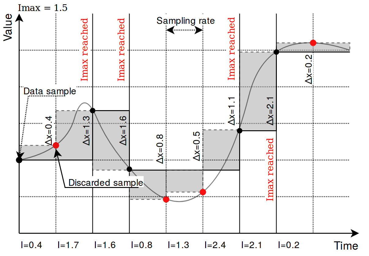](https://wiki.elseta.com/uploads/images/gallery/2020-10/image-1601977355078.png)
Picture. Result of using an integral threshold:
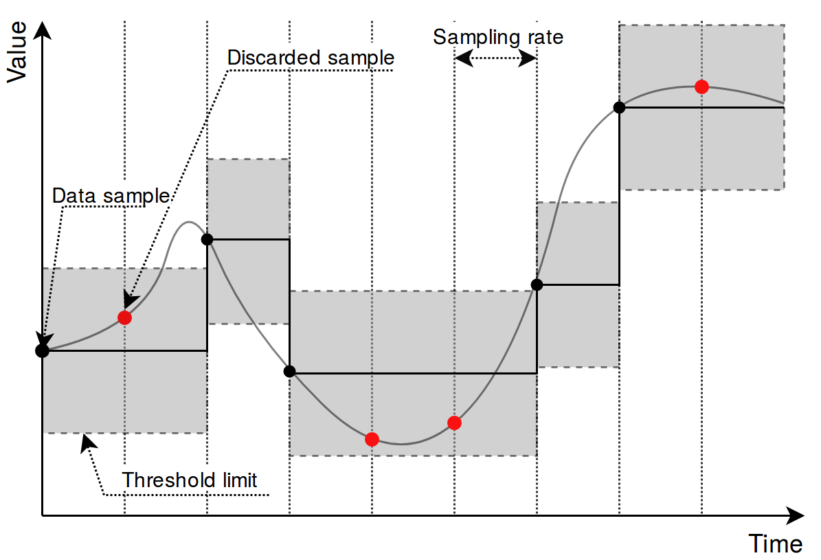
### Signal recalculation operation priority
A value generated by some protocol usually has to be recalculated in one way or another. This might mean changing the value of an argument as well as adding flags needed for other protocols to correctly interpret results. As recalculation is a sequential process, some actions are done before others. The sequence of operations done to a value is as follows:
- *Edition of attributes*. Attributes for further interpretation are added. This might, for example, include a flag to show that a signal resembles an answer to a command;
- *Mathematical calculations*. **multiply**, **add**, **bit\_select,** and **math\_expression** columns are evaluated here;
- *Usage of last value*. The decision if last value for a signal should be used if a new value of a signal is not a number (NaN) or contains a non-topical (NT) flag;
- *Limiting of values*. If a value exceeds a lower or higher configured limit, the value is approximated not be lower (or higher) than the limit. An additional overflow (OV) flag is added as frequently used in IEC-60870-5 protocols;
- *Suppression of values*. As electrical circuits can be noisy, protocols may generate multiple values in a short amount of time. What is more, some values are considered as intermediaries and ideally should not be sent to SCADA unless they stay in the same state for some amount of time. **suppression\_values** and **suppression\_time\_ms** are used to configure this functionality;
- *Threshold* checking. If a new signal doesn’t cross a threshold target value, the value is suppressed and not used in further stages. **absolute\_threshold, integral\_threshold, integral\_threshold\_interval, threshold\_units** columns are used to configure this functionality.
Not all of the elements in this sequence have to be configured, missing operations are skipped and values are fed to a further stage of signal recalculation.
### `number_type` field
This field is required for some protocols to determine a method to retrieve a signal value from hexadecimal form. Available values:
• **FLOAT** - 32-bit single precision floating point value according to IEEE 754 standard
• **DOUBLE** - 64-bit double precision floating point value according to IEEE 754 standard
• **DIGITAL** - 1-bit boolean value
• **UNSIGNED8** - 8-bit unsigned integer (0 - 255)
• **SIGNED8** - 8-bit signed integer (-128 - 127)
• **UNSIGNED16** - 16-bit unsigned integer (0 - 65535)
• **SIGNED16** - 16-bit signed integer (-32768 - 32767)
• **UNSIGNED32** - 32-bit unsigned integer (0 - 4294967295)
• **SIGNED32** - 32-bit signed integer (-2147483648 - 2147483647)
• **UNSIGNED64** - 64-bit unsigned integer (0 - 18446744073709551615)
• **SIGNED64** - 64-bit signed integer (-9223372036854775808 - 9223372036854775807)
Number conversion uses **big-endian** byte order by default. Converted data will be invalid if the byte order on the connected device side is different. In such a case, byte swap operations can be used. Adding swap prefixes to number types will set different byte orders while converting values. Following swap operations are available:
- **SW8** - Swap every pair of bytes (8 bits) (e.g., **0xAABBCCDD** is translated to **0xBBAADDCC**);
- **SW16** - Swap every pair of words (16 bits) (e.g., **0xAABBCCDD** is translated to **0xCCDDAABB**);
- **SW32** - Swap every pair of two words (32 bits) (e.g., **0x1122334455667788** is translated to **0x5566778811223344**);
| Address | 0 | 1 | 2 | 3 | 4 | 5 | 6 | 7 |
| Original number | Byte 0 | Byte 1 | Byte 2 | Byte 3 | Byte 4 | Byte 5 | Byte 6 | Byte 7 |
| SW8 | Byte 1 | Byte 0 | Byte 3 | Byte 2 | Byte 5 | Byte 4 | Byte 7 | Byte 6 |
| SW16 | Byte 2 | Byte 3 | Byte 0 | Byte 1 | Byte 6 | Byte 7 | Byte 4 | Byte 5 |
| SW32 | Byte 4 | Byte 5 | Byte 6 | Byte 7 | Byte 0 | Byte 1 | Byte 2 | Byte 3 |
| SW8.SW16 | Byte 3 | Byte 2 | Byte 1 | Byte 0 | Byte 7 | Byte 6 | Byte 5 | Byte 4 |
| SW8.SW32 | Byte 5 | Byte 4 | Byte 7 | Byte 6 | Byte 1 | Byte 0 | Byte 3 | Byte 2 |
| SW8.SW16.SW32 | Byte 7 | Byte 6 | Byte 5 | Byte 4 | Byte 3 | Byte 2 | Byte 1 | Byte 0
|
Where Byte x, means bit x position in the byte.
Add a dot-separated prefix to the number format to use byte swapping. Multiple swap operations can be used simultaneously. For example, use `SW8.SW16.SIGNED32` it to correctly parse a 32-bit signed integer in a little-endian format. Table 35 shows in detail how bytes, words, or double-words can be swapped and how swapping functions can be combined to make different swapping patterns. The table shows how byte swap is done for 64-bit (8-byte) numbers. It doesn’t matter if it is an unsigned/signed integer or double, byte swapping is considered a bit-level operation. If a number is shorter than 64 bits, the same logic applies, the only difference is the unavailability of some swapping operations (`SW32` for 32-bit and smaller numbers). Using such an unavailable operation might lead to undefined behavior.
### Linking signals
Signals can be linked together to achieve data transfer between several protocols. If a signal source is defined, all output from that source will be routed to the input of the target signal. This way events polled from a Modbus device (e.g., [Modbus](https://wiki.elseta.com/books/rtu-usage/page/modbus "Modbus protocol"), [IEC 60870-5](https://wiki.elseta.com/books/rtu-usage/chapter/protocols-configuration "Protocols - configuration"), etc.) can be delivered to an external station over a different protocol. A signal source is required if a signal is created on a slave protocol configuration to link events between protocols.
#### Example 1:
To read a coil state from a Modbus device and transfer it to [IEC 60870-5-104](https://wiki.elseta.com/books/rtu-usage/page/iec-60870-5-104 "IEC 60870-5-104") station, the following steps may be taken:
1. Create a Modbus master configuration in the Devices sheet.
2. Create an IEC 60870-5-104 slave configuration in the Devices sheet.
3. Create a signal on the master device to read coil status (function 1).
4. Create a signal on the slave device with a single point type (data\_type = 1).
5. Set **source\_device\_alias** and **source\_signal\_alias** fields on slave device signal to match **device\_alias** and **signal\_alias** on master device’s coil signal.
1. Follow steps 1-3 from example 1.
2. Create a signal on the slave device with a single command type (data\_type = 45).
3. Set source\_device\_alias and source\_signal\_alias fields on the master configuration coil signal to match device\_alias and signal\_alias on the slave device’s command signal. Coil will be written to a value received by a command.
4. Set source\_device\_alias and source\_signal\_alias fields on the command signal to match device\_alias and signal\_alias on the master device’s coil signal. A command termination signal will be reported to the station on the coil write the result.
For additional information regarding the configuration of IEC 60870-5-101/103/104 protocols, please refer to ”IEC 60780-5-101/103/104 PID interoperability for WCC Lite devices”, accordingly.
### Separators
These operators can be used when defining two or more values in a single cell. For example, source\_signal\_alias and source\_device\_alias from different signals have to be written in the same cell but separated by the separators listed below. This is useful when using the operation parameter when trying to do mathematical operations on more than one signal.
- “ “
- (newline)
- “;”
- “,”
# 18.3 Mathematical functions
Signal value might require some recalculation or signal update prior to being sent. Understandably, existing columns in Excel configuration like `multiply`, `add`, `bit_select` might not be flexible enough. To overcome these limitations, symbolic mathematical expressions can be configured to do calculations automatically on every update of a signal.
It should be noted that filling mathematical expression disables other mathematical scalar operations for a single value such as `multiply`, `add` or `bit_select`. Other functions (primarily between several signals) are still available such as operation.
### Feature list:
- Optimized for speed
- High parsing performance
- if-then-else operator with lazy evaluation
- Default implementation with many features
- 25 predefined functions
- 18 predefined operators
- Unit support
- Use postfix operators as unit multipliers (3m -> 0.003)
### Mathematical functions
Table. Supported mathematical functions:
| Name | Argument count | Explanation |
| sin | 1 | sine function (rad)
|
| cos | 1 | cosine function (rad)
|
| tan | 1 | tangent function (rad)
|
| asin | 1 | arcus sine function (rad)
|
| acos | 1 | arcus cosine function (rad)
|
| atan | 1 | arcus tangens function (rad)
|
| sinh
| 1 | hyperbolic sine function
|
| cosh | 1 | hyperbolic cosine
|
| tanh | 1 | hyperbolic tangens function
|
| asinh | 1 | hyperbolic arcus sine function
|
| acosh | 1 | hyperbolic arcus tangens function
|
| atanh | 1 | hyperbolic arcur tangens function
|
| log2 | 1 | logarithm to the base 2
|
| log10 | 1 | logarithm to the base 10
|
| log | 1 | logarithm to base e (2.71828...)
|
| ln | 1 | logarithm to base e (2.71828...)
|
| exp | 1 | e raised to the power of x
|
| sqrt | 1 | square root of a value
|
| sign | 1 | sign function -1 if x<0; 1 if x>0
|
| rint | 1 | round to nearest integer
|
| abs | 1 | absolute value
|
| min | variable | min of all arguments
|
| max | variable | max of all arguments
|
| sum | variable | sum of all arguments
|
| avg | variable | mean value of all arguments
|
| floor | 1 | round down to the nearest integer
|
It should be noted that trigonometric functions (excluding hiperbolic functions) only support arguments in radians. This means that arguments for this function have to be recalculated if angle is defined in degress.
Value recalculation is only triggered on signal change of the preconfigured signal. That means that using other signals (via TagValue() call) does not trigger value update.
Some mathematical expression cannot be mathematically evaluated in some conditions, for example, square root cannot be found for negative numbers. As complex numbers are not supported, result is then equal to Not a Number (NaN). These results are marked with an invalid (IV) flag.
### Binary operations
Table. Supported binary operators:
| Operator | Description | Priority |
| =
| assignment
| -1 |
| »
| right shift
| 0 |
| «
| left shift
| 0 |
| &
| bitwise and
| 0 |
| |
| bitwise or
| 0 |
| &&
| logical and
| 1 |
| ||
| logical or
| 2 |
| <=
| less or equal
| 4 |
| >=
| greater or equal
| 4 |
| !=
| not equal
| 4 |
| ==
| equal
| 4 |
| > | greater than
| 4 |
| < | less than
| 4 |
| + | addition
| 5 |
| - | subtraction
| 5 |
| \* | multiplication
| 6 |
| %
| modulo
| 6
|
| / | division
| 6
|
| ^
| raise x to the power of y
| 7 |
Ternary operators can be used. This expression can be compared to the operator supported by C/C++ language (Table 39). Condition is written before a question (?) sign. If condition is true, result after question sign is selected. If condition is false, result after colon (:) is selected.
### Ternary operations
Table. Supported ternary operators
| Operator | Description | Remarks |
| ?:
| if then else operator
| C++ style syntax
|
### Examples
Users can construct their own equation by using the aforementioned operators and functions. These examples can be seen in Table below.
Table. Example expressions
| Expression
| Description
|
| value \* 0.0001
| Multiply the tag by a constant.
|
| value + TagValue(”tag/dev\_alias/sig\_alias/out”)
| Add value of tag/dev\_alias/sig\_alias/out to the current tag.
|
| sin(value)
| Return a predefined sine function value of the tag.
|
| (value>5)? 1: 0
| If the value is greater than 5, the result should be equal to 1, otherwise - equal to 0
|
Variable called value is generated or updated on every signal change and represents the signals being configured. If another value from tag list is intended to be used, one should use `TagValue()` function to retrieve its last value.
The inner argument of `TagValue()` function has to described in a Redis topic structure of WCC Lite. That means that it has to be constructed in a certain way. Quotes should be used to feed the topic name value, otherwise expression evaluation will fail.
Every Redis topic name is constructed as tag/\[device\_alias\]/\[signal\_alias\]/\[direction\]. Prefix tag/ is always used before the rest of argument. `device_alias` and `signal_alias` represent columns in Excel configuration. direction can have one of four possible values - rout, out, in, rin; all of which depend on the direction data is sent or acquired device-wise. For example, out keyword marks data sent out of WCC Lite device, whereas in direction represents data that WCC Lite is waiting to receive, for example, commands. Additional r before either direction means that data is raw, it was is presented the way it was read by an individual protocol.
### Extra functions
Several functions are defined make tag operations possible:
- `TagValue(key)` - returns last known value of tag identified by redis key;
- `TagFlag(key)` - returns 1 if tag flag exists. Name format is: ”key flag”. For example to check if tag is notopical, name would be ”tag/19xxxxxxx/x/x nt”;
- `TagAttribute(key)` - similar to TagFlag, but returns a numeric value of a tag attribute;
- `TagTime(key)` - returns UNIX timestamp in milliseconds of a last know tag value.
# 18.4 Uploading configuration
As of WCC Lite version v1.4.0, there are three separate ways to import the configuration: import an Excel file via the web interface, generate compressed configuration files and later upload them via the web interface; or generate compressed configuration files and upload them via utility application.
For WCC Lite versions v1.4.0, the name of the file is shown in Protocol Hub->Configuration. Older versions only allow configuration files to be stored to a file called phub.xlsx and later downloaded with a custom-built name reflecting the date of a download. Upgrade process from older version to versions v1.4.0 and above when preserving configuration files automatically makes the necessary changes to enable this new functionality of WCC Lite.
If a user intends to **downgrade** the firmware to versions older than version v1.4.0 from newer versions, he/she must first download the configuration files and later reupload the configuration after finishing the upgrade process.
### Importing an Excel file
Excel files can be imported without any external tools. This option can be used where there is no internet connection or only minor change has to be applied. This way of importing is not suitable for the validation of Excel configuration files.
**Generating configuration is a resource-intensive task.** It might take up to 10 minutes depending on configuration complexity
Supported types of an Excel configuration: .xlsx, .xlsm, .xltm, .xltx
To upload an Excel file, open Protocol Hub->Configuration screen in Web interface, select Configuration file, and press Import configuration.
### Generating .zip file
To accelerate the task of generating configuration a computer can be used. For this users should download the WCC Excel Utility application. Upon opening an application, the user should search for a field called Excel file which lets to choose an Excel file for which a conversion should be made. The output file should be filled out automatically, however, this value can be edited.
To make a conversion press Convert. If there are no errors found in the configuration, the output file should contain the generated configuration, otherwise, an error message is shown to a user.
This .zip file can be uploaded via the Web interface, using the same tools as used for import of an Excel file.
### Uploading configuration remotely
As of WCC Lite version, v1.4.0 generated configuration files can be uploaded with a click of a button in the Excel Utility. There are four parameters (not counting the configuration file itself) that have to be filled in before starting upload:
- *Hostname*: an IP address for the device to connect to. This field conforms to hostname rules, therefore, if an invalid value is selected, it is reset to default (192.168.1.1);
- *Port*: a PORT number to which an SSH connection can be made; valid values fall into a range between 1 and 65535; if an invalid value is selected, it is reset to default (22);
- *Username*: a username which is used to make an SSH connection; make sure this user has enough rights, preferably root;
- *Password*: a password of a user used for establishing an SSH connection;
Configuration can only be uploaded if a port used for SSH connection is open for IP address filled in the hostname entry field. Please check WCC Lite firewall settings in case of connection failure.
To upload a configuration remotely, press Upload configuration. If no errors occur, you should finally be met with text output mentioning configuration has been applied. During the course of the upload process, the aforementioned button is disabled to prevent spanning multiple concurrent processes.
# 18.5 Virtual device
### General
The virtual device is a device that you can use to calculate additional math or keep a counter. It doesn't bind to any protocol and only works when its math expression is used.
Virtual device functionality is only available since firmware version v1.6.3, of WCC Lite.
### Configuring Virtual device
To configure WCC Lite to use the virtual device you must configure the device and signal sheets.
*Virtual device parameters for Device tab:*
| **Parameter**
| **Type**
| **Description**
| **Required
| **Default value**
(when not specified)
| **Range**
|
| Min
| Max
|
| name | string | User-friendly device name | Yes |
|
|
|
| description | string | Description of the device | No |
|
|
|
| device\_alias | string | Device alias to be used in the configuration | Yes |
|
|
|
| protocol | string | Selection of protocol | Yes |
| **virtual**
|
*Virtual device parameters for Signals tab:*
| **Parameter**
| **Type**
| **Description**
| **Required
| **Default value**
(when not specified)
| **Range**
|
| Min
| Max
|
| signal\_name | string | User-friendly signal name | Yes | |
| |
| device\_alias | string | Device alias from a Devices tab | Yes |
|
|
|
| signal\_alias | string | Unique signal name to be used | Yes |
|
|
|
| math\_expression | string | Field to calculate specific math.
You must enter the signal you want to use.
| Yes |
|
|
The only field that is a must to use the virtual device is the *math\_expression* field. Here you need to enter the signal which you want to associate it with. Some examples of what it can do:
- Hold a specific tag value.
- Calculate a specific math function with many signals, that you can, later on, pass to another device.
- Add tag value to the current value, to create a counter.
# 19 WCC Lite internal signals
### Overview
The WCC Lite contains several internal data points for readout and control which can be accessed via the Pooler service.
### Configuration
#### Devices section
In the devices section, only the protocol, scan\_rate\_ms and poll\_delay\_ms are to be configured for this type of device.
##### WCC Lite internal signals
| **Parameter** | **Type** | **Description** | **Required** | **Default Value**
(when not specified)
| **Range**
|
| name | string
| User-friendly device name | Yes | | |
| device\_alias | string | Alphanumeric string to identify a device | Yes | |
|
| protocol |
| Protocol identifier Internal data | Yes |
| **Internal data** |
| scan\_rate\_ms | integer | Update rate | No | 60000 |
|
| poll\_delay\_ms | integer | Poll delay | No | 200 |
|
It is advised to set scan\_rate\_ms to a value greater than 5000 ms as frequent scans may result in a significant overload of the internal data process.
#### The signals section
`tag_job` defines the tag job. This can be set to `gpio`, `board`, `netstat`, `gsm`, `led` and `process`. `tag_job_todo` defines the job sub job. This field should address the particular point of interest. There is also an extra trigger parameter which is optional. It allows changing when the signal switches between on and off and is only applicable on LED and GPIO parameters that can be set. The default trigger is value>0. When a **trigger** column is added the trigger can be changed by entering i.e. "value>10". This is useful when mapping a source signal to for example trigger a relay. An example of how to use a trigger is in the example configuration which is attached to this page. [Excel Configuration Example](https://wiki.elseta.com/attachments/33)
Digital-input GPIO will only work with Hardware versions 1.4 and above.
Certain GSM parameters will only work if a sim card is inserted.
| **job\_todo** | **Description** | **tag\_job\_todo** | **Description** |
| gpio
| ReadOnly parameters | digital-input | If the value is 1 then the digital input pin is high. If it's 0 then the digital-input value is low. |
| rs232-enable
| If the value is 1 then rs232 is enabled. If the value is 0 then rs485 is enabled. |
| Parameters that can be set. | sim-select
| Switch between sim1 and sim2. If the **value** is 0 then sim1 is selected. If the value is 1 then sim2 is selected. |
| modem-reset
| Making this value equal to 1 will reset the modem. |
| relay
| Making this value equal to 1 will activate the relay. |
| board
| Board info
| cpu-usage
| CPU usage % |
| ram-usage
| RAM usage % |
| mac-address
| Device MAC address |
| uptime
| Device uptime in seconds |
| fw-version
| Firmware version |
| hw-version
| Hardware version |
| modem-imei
| Modem IMEI number |
| modem-type
| Modem type:
0 - unknown
1 - single sim
2 - dual sim
|
| netstat|\[interface\] | Network statistics | TX
| Bytes transferred |
| RX | Bytes received |
| led
| LED status/control
| blue-heartbeat
| Heartbeat LED |
| blue-wlan
| WLAN LED |
| green-eth0 | ETH0 LED |
| green-eth1 | ETH1 LED |
| green-signal1
| Signal 1 LED |
| green-signal2
| Signal 2 LED |
| green-signal3
| Signal 3 LED |
| red-fault | Fault LED |
| process | Check if the process is running | \[process name\] | 1 or 0 is returned |
| gsm
| GSM information | rat-number
| GSM RAT number
|
| imsi-number
| GSM IMSI number |
| internet-status
| GSM Internet status |
| operator-number
| GSM operator number |
| roaming-status
| GSM roaming status |
| signal-quality
| GSM signal quality |
| sim-status
| SIM card status |
| date
| Current set time values. | year
| The current year set on the device |
| month
| The current month set on the device
|
| day
| The current day set on the device
|
| hour
| The current hour set on the device
|
| minute
| The current minute set on the device
|
| second
| The current second set on the device |
# 20 Programmable logic controller
A programmable logic controller (PLC) is a digital device adapted for control of processes which require high reliability, ease of programming and realtime responses. Such functionality has long since replaced hardwired relays, timers and sequencers which would be required to complete various tasks.
Programmable logic controllers usually had to conform to IEC 611313 standard which defines four programming languages: function block diagram (FBD), ladder diagram (LD), structured text (ST) and sequential function chart (SFC). This standard does not support distributed control systems therefore IEC 61499 standard was published in 2005. The standard is considered an extension of IEC 611313 standard.
WCC Lite supports PLC functionality while conforming to specifications of IEC 61499 standard.
# 20.1 IEC 61499
IEC 61499-1 defines the architecture for distributed systems. In IEC 61499 the cyclic execution model of IEC 61131 is replaced by an event driven execution model. The event driven execution model allows for an explicit specification of the execution order of function blocks. If necessary, periodically executed applications can be implemented by using the E\_CYCLE function block for the generation of periodic events.
IEC 61499 enables an application-centric design, in which one or more applications, defined by networks of interconnected function blocks, are created for the whole system and subsequently distributed to the available devices. All devices within a system are described within a device model. The topology of the system is reflected by the system model. The distribution of an application is described within the mapping model. Therefore, applications of a system are distributable but maintained together.
Like IEC 61131-3 function blocks, IEC 61499 function block types specify both an interface and an implementation. In contrast to IEC 61131-3, an IEC 61499 interface contains event inputs and outputs in addition to data inputs and outputs. Events can be associated with data inputs and outputs by WITH constraints. IEC 61499 defines several function block types, all of which can contain a behavior description in terms of service sequences:
Service interface function block – SIFB: The source code is hidden and its functionality is only described by service sequences;
• Basic function block - BFB: Its functionality is described in terms of an Execution Control Chart (ECC), which is similar to a state diagram (UML). Every state can have several actions. Each action references one or zero algorithms and one or zero events. Algorithms can be implemented as defined in compliant standards.
• Composite function block - CFB: Its functionality is defined by a function block network.
• Adapter interfaces: An adapter interface is not a real function block. It combines several events and data connections within one connection and provides an interface concept to separate specification and implementation.
• Subapplication: Its functionality is also defined as a function block network. In contrast to CFBs, subapplications can be distributed.
To maintain the applications on a device IEC 61499 provides a management model. The device manager maintains the lifecycle of any resource and manages the communication with the software tools (e.g., configuration tool, agent) via management commands.
# 20.2 4Diac framework
[](https://wiki.elseta.com/uploads/images/gallery/2020-10/image-1601992021990.png)
The PLC functionality in the WCC Lite is implemented using Eclipse 4diac framework, consisting of the 4diac IDE and the 4diac FORTE runtime. The system corresponds to IEC 61499, an extension of IEC 61131-3. For more in-depth instructions and function block reference please see the 4diac manual - this document is merely a quick start guide that emphasizes the specifics of tailoring the applications to run on the WCC Lite.
For this project 4Diac framework version 1.11.3 should be used.
The 4diac IDE application is used to model logic sequences. An output file, \*.fboot, is then generated and either loaded into the runtime for debugging purposes (functionality available from within the IDE), or uploaded into the controller for normal use via web interface.
During debugging, the output logic is executed directly in the runtime. Any logic loaded during debugging will be discarded after a reboot of the controller. Logic applications for regular use should be uploaded via the web interface.
It is possible to run multiple tasks at once. These tasks can either be implemented in the same screen or split into separate tasks. Please note, however, that all elements should have unique names, even between different tasks. As of 4diac IDE 1.11.3 this is not enforced between separate apps, however, 4Diac runtime application rejects such file purely because of naming issues.
The 4diac FORTE runtime is able to execute the aforementioned fboot files containing the logic. The FORTE runtime can be run on both the WCC Lite and a PC for debugging purposes. The runtime is integrated to interact with the REDIS database.
# 20.3 Example project
The best way to understand basics of 4Diac and WCC Lite collaboration is through an example project. This user manual intends to show the pieces needed to run PLC applications on WCC Lite. It is not intended to be definitive guide on how to use 4Diac IDE or how to interpret IEC 61499 standard.
During (at least) the first start of the IDE user will be asked to select a directory for the workspace as in Figure. Workspace is used to save files needed for projects.
[](https://wiki.elseta.com/uploads/images/gallery/2020-10/image-1601992159243.png)
[](https://wiki.elseta.com/uploads/images/gallery/2020-10/image-1601992177394.png)
After that a user should be met by the welcome window as in Figure 20. If such window is not shown, one can create create project by selecting File->New->Project and filling in the required fields (figure 21).
To create a simple application, simply drag and drop objects from the palette to the canvas and wire them accordingly. Event trigger and data pathways cannot be connected to one another. Displayed below is an example of a simple blinker application (figure 22).
Having less wiring by connecting several signals to same subnet as PCB designer (such as Altium Designer) as of 4Diac IDE 1.11.3 is not supported. However, if some parts are used frequently, it is highly advised to have less wiring by simply compiling several elements into a subapplication. For this, you would have to select elements to be grouped, press right key and select New Subapplication. You can later change names of such elements and its pins.
[](https://wiki.elseta.com/uploads/images/gallery/2020-10/image-1601992239152.png)
[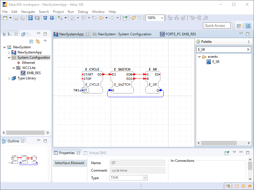](https://wiki.elseta.com/uploads/images/gallery/2020-10/image-1601992245178.png)
In the System Configuration section, drag and drop a FORTE\_PC device, an Ethernet segment and link them (figure 23). For debugging in the local (PC) runtime, leave the address ”localhost:61499”. For testing on a WCC Lite, enter the IP address of the device, along with the port number (which by default is 61499 as well).
[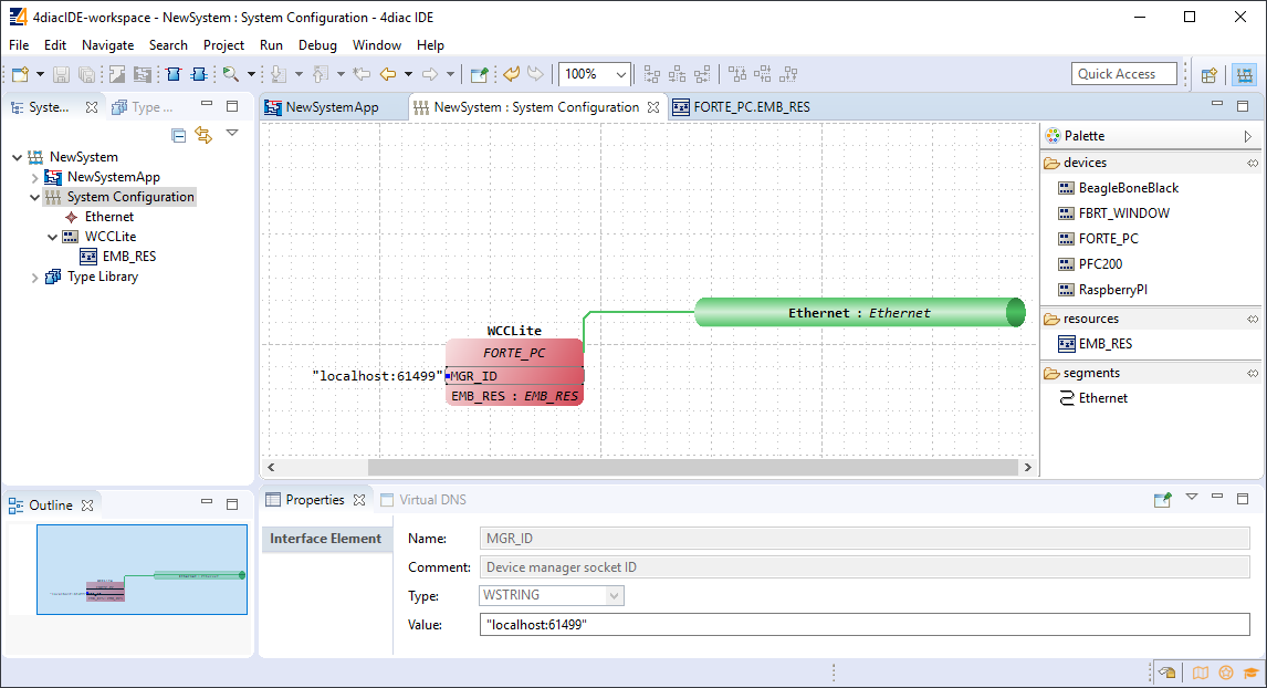](https://wiki.elseta.com/uploads/images/gallery/2020-10/image-1601992273595.png)
In order to deploy the application, the circuit needs to be mapped to the controller. For a non-distributed application (distributed application cases will not be discussed in this chapter), all the FBs of the application need to be selected and mapped to the configured controller as shown in figure 24.
[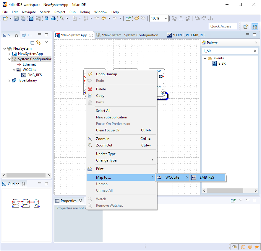](https://wiki.elseta.com/uploads/images/gallery/2020-10/image-1601992299991.png)
To start the application execution, an initial trigger needs to be present. For a non-distributed application, the initial event trigger needs to be wired from the START function block in the resource section as shown in figure 25.
[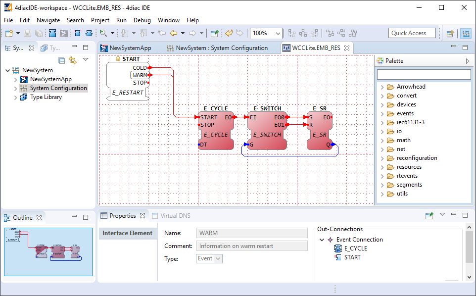](https://wiki.elseta.com/uploads/images/gallery/2020-10/image-1601992323578.png)
[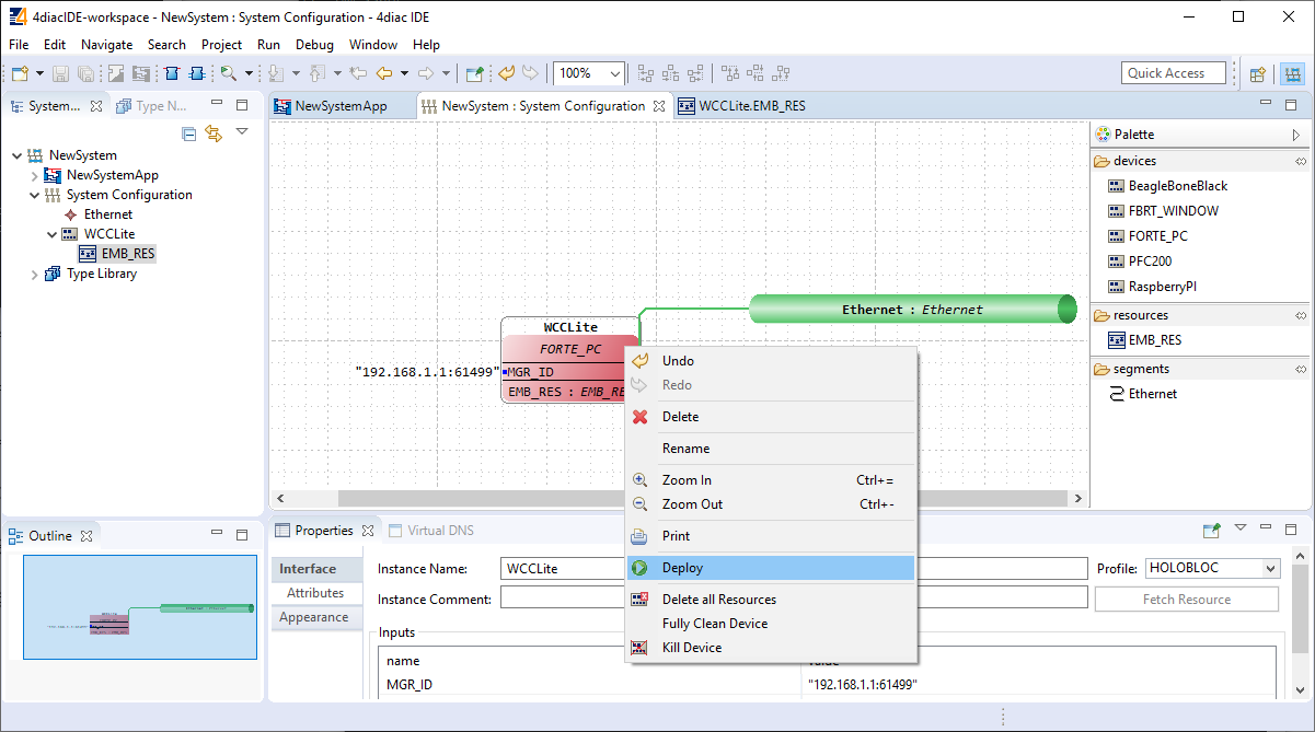](https://wiki.elseta.com/uploads/images/gallery/2020-10/image-1601992330383.png)
To deploy the application, go to the System Configuration tab and simply select ”Deploy” from the right-click menu of the controller device (figure 26). If a running application exist in the runtime, you may be asked whether you want to replace it. This will only overwrite the application in the memory and not the storage. If the controller is restarted, the old application will be loaded from the
non-volatile memory of the controller.
# 20.4 Configuring data endpoints
To use WCC Lite as a programmable logic controller, it needs to be configured in a particular way. The PLC functionality of the WCC Lite only allows for the use of data that is has been configured in the Excel configuration spreadsheet. This has been done for security purposes and to preserve transmission medium only for data that is available. Only topics defined in the configuration can post or get data. If a certain data entry exists but it has not been linked to a PLC program, all calls from PLC runtime application to Redis database will be ignored. Therefore it is highly advised to prepare and upload the Excel configuration before using this signal in the PLC application.
Some parameters are mandatory for PLC usage. These parameters are shown in two tables below (one for Devices, one for Signals tab). Please note that other parameters can be used as well, but are not covered because they aren’t specific to PLC functionality.
Table. Mandatory parameters for Devices tab
| Parameter | Type | Description |
| name
| string
| User-friendly device name
|
| device\_alias
| string
| Device alias to used in configuration
|
| enable
| boolean | Enabling/disabling of a device
|
| protocol
| string
| Selection of protocol (IEC 61499)
|
Table. Mandatory parameters for Signals tab
| Parameter | Type | Description |
| signal\_name
| string
| User-friendly signal name
|
| device\_alias
| string
| Device alias from a Devices tab
|
| signal\_alias
| string | Unique signal name to be used
|
| source\_device\_alias
| string
| device\_alias of a source device
|
| source\_signal\_alias
| string
| signal\_alias of a source signal
|
If an upload consisting of configuration for IEC 61499 has been succesful, one should be able to access a configuration stored in /etc/iec61499.json file where protocol-specific parameters are shown in a JSON format. If the file is missing, make sure you have a correct firmware version installed and haven’t made any typing errors.
Parameters mentioned earlier, namely device\_alias and signal\_alias, are the only parameters one needs to fill to bind Excel configuration to 4Diac framework. Two types of blocks are used for data transmission - PUBLISH blocks to write data to REDIS database and SUBSCRIBE blocks to acquire data from database as soon as it changes its value. Both of them have an ID connection. To connect a block to a datapoint, one should set this pin as raw\[\].redis\[device\_alias,signal\_alias\], e.g. raw\[\].redis\[example\_plc\_device,example\_plc\_signal\_alias\].
An example with SUBSCRIBE and PUBLISH function blocks is shown below in image below.
Subscribe and publish examples[](https://wiki.elseta.com/uploads/images/gallery/2020-10/image-1602661793915.png)
Outputs of variable type ANY cannot be directly wired to inputs of the same type and therefore need to be explicitly typed using transitional function blocks
No more than 20 tags should be published over a period of 5 seconds, as this may overfill the queue. A ”publish only on change” policy is advised.
Currently only PUBLISH\_1 and SUBSCRIBE\_1 function blocks are supported.
If every step until now has been succesful, a user could now start debugging a PLC application.
# 20.5 Debugging an IEC 61499 application
After a project has been built and binded to an existing Excel configuration, a user would normally want to check if every part is working according to the prior requirements before compiling finished project and uploading it to production. Both 4Diac framework and WCC Lite offer tools for flexible debugging.
There is a possibility that 4Diac FORTE might not start as a process. It may happen if multiple faults occured and process has stopped. Process is also programmed to not start if no excel configuration file is found, therefore a user should make sure that Excel configuration is uploaded and ready for use.
Individual function blocks can be set to Watch mode: events can be triggered and values can be forced at inputs or outputs (look into images bellow). To monitor the function blocks, the application should be deployed and the IDE should be in Online mode (Debug -> Monitor System -> NewSystem).
Selecting watch mode:
[](https://wiki.elseta.com/uploads/images/gallery/2020-10/image-1602662191072.png)
Function blocks in watch mode:
[](https://wiki.elseta.com/uploads/images/gallery/2020-10/image-1602662206569.png)
Seeing information dynamically updated on 4Diac IDE might be very informative, however, some applications might require accesing WCC Lite via command-line interface. For example, in case of information not being updated one would want to assure that 4Diac FORTE in WCC Lite is not filtering data out but sending it to internal database (Redis). To run 4Diac FORTE debug from command-line interface, a user should write forte and press Enter. All possible choices are shown by adding -h flag. More flags are shown in a Table bellow. Make sure to stop any running process that could use the address that 4Diac framework is going to use.
Table. 4Diac FORTE command line debugging options:
```
-h - Display help information
-c : - Set the listening IP and port for the incoming connections
-r - Show redis messages
-d - Set debugging level
-f - Set the boot-file where to read from to load the applications
```
###
# 20.6 Generating and uploading FORTE logic file
After the PLC design is finished and debugged, such design can be compiled into FBOOT file and uploaded to one or multiple devices to be used in production. As application being debuggged is not automatically considered as a default application, one should be uploaded explicitly via web interface.
To generate FORTE boot-files a user should select Run->Create FORTE boot-file.... After that one should select devices which should have their boot files created as well as additional devices’ properties and directory where these files should be stored as in picture bellow.
Generating FBOOT file:[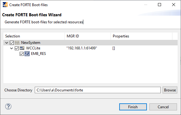](https://wiki.elseta.com/uploads/images/gallery/2020-10/image-1602662453356.png)
Upload button for FORTE file in web interface can be found in Protocol Hub tab, Configuration screen (FORTE boot file upload supported for versions v1.4.0 and above). You should see a view as in picture below.
WCC Lite Web interface. Upload and download of 4Diac configuration files:
[](https://wiki.elseta.com/uploads/images/gallery/2020-10/image-1602662559336.png)
After the file has been imported one should be able to download it from the same screen as seen in the picture before.
Please note that only files with \*.fboot extension are allowed.
Uploading a file saves it's name and shows it in the web interface. It is advised to carefully choose a filename to separate different versions of PLC application files.
# 20.7 Distributed control application
IEC 64199 standard introduced requirements for a distributed control. This means that multiple devices can change information between them and make their own decisions based on the data they receive from other sources. This enables distributed applications between multiple WCC Lite devices and all other devices that support IEC 61499.
Communication between devices can be configured using:
- Publish/Subscribe function blocks (via UDP packets);
- Client/Server function blocks (via TCP packets).
A Publish block can publish data messages using UDP multi-cast addresses meaning that multiple devices would be able to simultaneously get the same data. However, one would have to make sure that all of the devices support multi-cast option.
This user manual will only cover setting up point-to-point communication between devices via Publish/Subscribe blocks. For more information on communication between several IEC 61499 devices please check documentation for Eclipse 4diac framework.
Let’s say we would like to count how many times the light has been turned on. For this we can add counting functionality to application shown in picture below. The application should run on 2 devices. The blinking part of the application will run on a 4diac FORTE and the count on another 4diac FORTE, see the architecture below. The two different programs running on two separate WCC Lite devices emulate two PLCs. Two different devices can be identified by different colors of function blocks. One can identify device and it properties by accessing System Configuration screen as seen below. Yellow function blocks belong to WCC\_212 device which can be accessed through 192.168.4.212 (port number 61499) whereas brown function blocks belong to WCC\_218 device which can accessed through 192.168.4.212 (port number 61499).
Example blinking application as a distributed system:[](https://wiki.elseta.com/uploads/images/gallery/2020-10/image-1602662769321.png)
Example system configuration for a distributed system:[](https://wiki.elseta.com/uploads/images/gallery/2020-10/image-1602662862391.png)
Example app for blinking part of a distributed system:[](https://wiki.elseta.com/uploads/images/gallery/2020-10/image-1602662875556.png)
Example app for counting part of a distributed system:[](https://wiki.elseta.com/uploads/images/gallery/2020-10/image-1602662888137.png)
To count the blinking, two new Function Blocks (FBs) have been added to the existing application for a different device (WCC\_218):
- E\_PERMIT
- E\_CTU
To communicate between devices, an additional PUBLISH\_X/SUBSCRIBE\_X pair must be used. As one can identify, these blocks are not seen when looking at a whole distributed system and should be seen as an intermediary between devices.
The PUBLISH\_X FB is used to send messages over the network which are received by an according SUBSCRIBE\_X FB. Every time a REQ is triggered, a message is sent according to the ID input. With the value of the ID input you can specify what specific network protocol you would like to use (e.g., MQTT). If you don’t specify a dedicated protocol the default as defined in the ”IEC 61499 Compliance Profile for Feasibility Demonstrations” is used. The number X in PUBLISH\_X is the number of data elements that you want to send in the message. Since we are only sending one value we used PUBLISH\_1.
The used ID value specifies an IP:PORT pair.
# 21 Lua script runner
### Introduction
Lua is a powerful, efficient, lightweight scripting language. It has been used in many industrial applications with an emphasis on embedded systems. Lua has a deserved reputation for performance. To claim to be "as fast as Lua" is an aspiration of other scripting languages. Several benchmarks show Lua as the fastest language in the realm of interpreted scripting languages. Lua is fast not only in fine-tuned benchmark programs, but in real life too. Substantial fractions of large applications have been written in Lua.
In WCC Lite system Lua is used for extending the functionality of excel configuration adding an interface to the existing signal-linking engine. Provided functions enable to recreate PLC functionality and modify any value with ease.
### Overview
##### Execution types:
Lua runner provides 3 execution modes: interval, date, signal, which can be specified in **execution\_type**.
**Interval**: executes provided script based on provided time interval in **execution\_parameter**. It uses milliseconds, meaning if 500 value is provided, then the script is executed every 500 milliseconds.
**Date:** schedules a script execution based on provided cron expression in **execution\_parameter**. The format consists of 6-7 fields separated by space.
For example, 0 0 \* \* \* \* will execute the script at every hour mark. There are a lot of online cron expression parsers or generators to convert this expression to a more understandable sentence. [https://crontab.cronhub.io/](https://crontab.cronhub.io/)
**Signal:** uses source signal provided in signal sheet to trigger script execution. Another non excel signal can be provided in **execution\_parameter** attribute. As an example, if a signal in excel configuration has an attribute **execute** with value 1, and a source signal specified in **source\_device\_alias, source\_signal\_alias**, then if a value event happens to the source signal, the script will be executed. More than one signal can have **execute** attribute.
##### Additional functions:
To interface with existing signals and extend the available lua functions some extra functions were added:
**get, set, publish,** and **subscribe** functions are used to get the values configured in excel configuration or to communicate with other scripts.
A signal value in wcc lite system consists of 3 sub-values: **value**, **time**, and **attributes. get** function is used to get all the sub-values or **get\_value**, **get\_time** and **get\_attributes** to get only one of the sub-values. To execute this command, a signal has to be specified: **get(signal.value1).** A signal is specified by a string "tag/<device\_alias>/<signal\_alias>" or a table that is created from **iterator** parameter in excel configuration. For example:
```Lua
-- the default iterator is signals, that means there is a table 'signals' generated from excel signals
signals["tag1"] = "tag/device_alias/tag1" -- tag1 would be the signal_alias
-- to get the value of this signal:
local variable = get_value(signals.tag1)
local variable = get_value(signals["tag1"]) -- both methods are viable
-- and the 'variable' will have the value of tag1 signal
-- get function will return the value of source signal that was sent to this signal
```
Function **publish** is used to send a value to other signals:
```Lua
publish(signals.tag2, 90) -- this function will send 90 with current time to the signal tag2
publish(signals.tag2, {value = 60, time = "123456789", attributes = "iv,nt,sb"})
-- above command is used when other sub values are needed to be specified
-- and the signal-linker will send it to another signal
-- if this signal was specified as source signal in another protocol signal
```
To provide different time and attributes to the publish function, a table of these 3 values has to be specified, time can be omitted. An example of the table is returned by the **get** function.
These two functions will be used the most, others are included for communication between different scripts in a more complex system.
**set** function set the value of the signal, without sending an event of change:
```Lua
set(signal.tag3, 50) -- this command will set the value of the signal tag3
-- because it is a set function, other protocols will not see a change
-- and the value will not be accessible
-- it is only used with non excel signals
set("signal1", 60) -- now the signal1 tag will have a value
-- and another script will be able to use get to get this value
local value1 = get_value("signal1") -- value1 will be equal to 60 with current time
```
Function **subscribe** is used to wait (blocks code execution while waiting) for a value and get it. It is used the same as **get** function (does not have separate functions for sub-values). It should only be used if more complex communication between scripts is needed.
These functions are equivalent to REDIS functions.
Function **save** saves the specified value to flash memory for use after reboot. The same value sub-values apply to execution.
```Lua
save(signals.tag1, 50) -- this will save a value to tag1
-- after reboot or script runner process restart this value will be set to tag1
-- and will be accesible with get(signals.tag1)
-- this function will not set the value tag1 to 50
```
Function **time\_ms** returns current time in milliseconds and in UNIX format.
```Lua
local t = time_ms()
-- t will be equal to 1665389490555
-- if the date right now is Mon Oct 10 2022 08:11:30:555 GMT+0000
```
Function **sleep** is the same as Lua socket module function socket.sleep.
```Lua
sleep(1) -- will wait for 1 second
```
Additional functions for debug information are: **emerg, alert, crit, err, warning, notice, info, debug**. These functions correspond to levels from 0 to 7. The default level is 4, which means that the function from **emerg** to **warning** will be printed to syslog, unless specified differently in file **/etc/lua-runner.conf.**
```Lua
emerg("log message 0")
alert("log message 1")
crit("log message 2")
err("log message 3")
warning("log message 4")
notice("log message 5")
info("log message 6")
debug("log message 7")
```
These functions will require significant cpu resources even if the message log level is higher than default and no message is printed.
##### Web interface
The web interface is used to see what scripts are running, if there is a script provided, to stop/start a script. After configuring a device with lua runner as protocol, the script runner protocol hub tab will be populated with devices that where configured:
[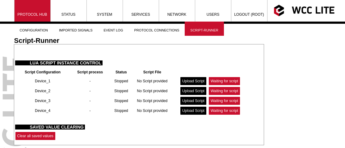](https://wiki.elseta.com/uploads/images/gallery/2022-10/image-1665406373895.png)
Then by pressing the Upload Script button, a script will be available to be selected (the name of the script will be changed to match device\_alias). When uploaded the script will not be started automatically, pressing start will be necessary.
[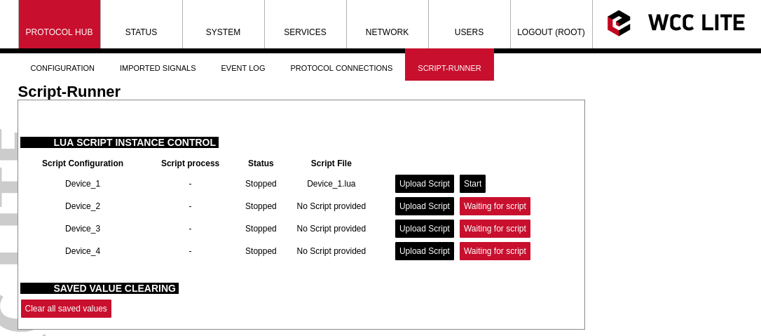](https://wiki.elseta.com/uploads/images/gallery/2022-10/image-1665408922682.png)
After pressing start, the script will be started, if there are errors it will try to start, but after a few attempts, it will stop.
[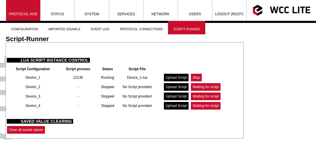](https://wiki.elseta.com/uploads/images/gallery/2022-10/image-1665409121771.png)
Clear all saved values button is used to clear the memory of saved values. Having a lot of values being saved is not healthy for the SD card and faults can happen. Also, script runner process initialization is slowed down when a lot of saved values are used.
### Configuration
#### Device configuration parameters:
| **Parameter**
| **Type**
| **Description**
| **Required
| **Default value**
(when not specified)
| **Range**
|
| Min
| Max
|
| name
| string | User-friendly name for a device
| Yes |
|
|
|
| device\_alias
| string
| Alphanumeric string to identify a device
| Yes
|
|
|
|
| description | string | Description of a device
| No |
|
|
|
| enable
| boolean
| Enabling/disabling of a device
| No
| 1
| 0
| 1
|
| protocol
| string
| Protocol to be used
| Yes
| | lua runner
|
| execution\_type
| string
| Execution type to be used
| Yes
| | interval, date, signal
|
| execution\_parameter
| int, string
| Parameters for execution
| Yes
| | interval time in ms,
date in cron format,
additional signal
|
| queue\_max
| int
| Maximum execution queue jobs
| No
| 3
| 0 to disable queue
|
| error\_limit
| int
| Error limit before stoping
| No
| 3
| 0 to disable
|
| keep\_alive\_time\_ms
| int
| Time to keep the script alive in ms
| No
| 600000
| 0 to disable
|
#### Signals configuration parameters:
| **Parameter**
| **Type**
| **Description**
| **Required
| **Default value**
(when not specified)
| **Range**
|
| Min
| Max
|
| signal\_name
| string | User-friendly name for a signal
| Yes |
|
|
|
| device\_alias
| string
| Alphanumeric string to identify a device
| Yes
|
| Must match device\_alias in the device sheet
|
| signal\_alias
| string
| Unique alphanumeric name of the signal to be Yes used
| Yes
|
|
|
|
| iterator
| string
| Lua table name to which signal is added
| No
| signals
| | |
| default\_value
| string
| Default value for a signal
| No
| | | |
| execute
| int
| Enable signal update trigger to execute script (only available for signal execution mode)
| No
| 0
| 0
| 1
|
Math (math\_expression, add, multiply, ) for source signals will not work for lua-runner device
### Debugging the script runner service
If configuration for script runner is set up, the process will start automatically. If configuration/script is missing or contains errors, process will not start. It is done intentionally decrease unnecessary memory usage.
Script runner runs a service called **lua-runner**. If the script doesn't start or does not work correctly, a user can launch a debug session from command line interface and find out what problem is causing it to not work. To launch a debugging session, a user should stop the script from web interface and run **lua-runner** command with respective flags and configuration as in the table given below.
Procedure for lua-runner service debugging:
- **Step 1**: Script must be stopped through web interface.
- **Step 2**: After script is stopped it must be started with the preferred configuration file (JSON files found in /etc/lua-runner, and the name corresponds to device\_alias) and a debug level 7: **lua-runner -c /etc/lua-runner/device\_alias.json -d7 -e.**
- **Step 3**: Once the problem is diagnosed normal operations can be resumed by starting the script through web interface.# 22 MQTT
### Introduction
MQTT (short for MQ Telemetry Transport) is an open OASIS and ISO standard (ISO/IEC PRF 20922) lightweight, publish-subscribe network protocol that transports messages between devices. The protocol usually runs over TCP/IP, although its variant, MQTT-SN, is used over other transports such as UDP or Bluetooth. It is designed for connections with remote locations where a small code footprint is required or the network bandwidth is limited.
The broker acts as a post office, MQTT doesn’t use the address of the intended recipient but uses the subject line called “Topic”, and anyone who wants a copy of that message will subscribe to that topic. Multiple clients can receive the message from a single broker (one to many capability). Similarly, multiple publishers can publish topics to a single subscriber (many to one).
Each client can both produce and receive data by both publishing and subscribing, i.e. the devices can publish sensor data and still be able to receive the configuration information or control commands. This helps in both sharing data, managing and controlling devices.
With MQTT broker architecture the devices and application becomes decoupled and more secure. MQTT might use Transport Layer Security (TLS) encryption with user name, password protected connections, and optional certifications that requires clients to provide a certificate file that matches with the server’s. The clients are unaware of each others IP address.
The broker can store the data in the form of retained messages so that new subscribers to the topic can get the last value straight away.
The main advantages of MQTT broker are:
- Eliminates vulnerable and insecure client connections
- Can easily scale from a single device to thousands
- Manages and tracks all client connection states, including security credentials and certificates
- Reduced network strain without compromising the security (cellular or satellite network)
Each connection to the broker can specify a quality of service measure. These are classified in increasing order of overhead:
- At most once - the message is sent only once and the client and broker take no additional steps to acknowledge delivery (fire and forget).
- At least once - the message is re-tried by the sender multiple times until acknowledgement is received (acknowledged delivery).
- Exactly once - the sender and receiver engage in a two-level handshake to ensure only one copy of the message is received (assured delivery).
WCC Lite supports MQTT messaging compatible with MQTT v3.1 standard (starting from version **v1.4.0**). Such messaging is possible via mapping of Redis and MQTT data therefore data can be transmitted from any protocol that is supported by WCC Lite.
All standard functions, except for data encryption, are supported. Encrypted messages are not supported yet, therefore to ensure security a user would have to use a VPN service. A user can choose from three different Quality of Service levels, select if messages are to be retained, authenticate users and optionally send Last Will messages.
To configure WCC Lite a user can fill in the needed parameters in Excel configuration. These parameters are shown in the two tables below.
Table. MQTT parameters for Devices tab
| **Parameter**
| **Type**
| **Description**
| **Required
| **Default value**
(when not specified)
| **Range**
|
| Min
| Max
|
| name | string
| User-friendly device name
| Yes |
|
|
|
| device\_alias | string
| Device alias to be used in the configuration
| Yes |
|
|
|
| enable | boolean | Enabling/disabling of a device
| No | 0 | 0 | 1 |
| protocol | string
| Selection of protocol
| Yes |
| MQTT |
| ip | string
| MQTT broker IP address/Domain name selection
| Yes |
|
|
|
| port | integer | MQTT broker port selection
| No | 1883 |
|
|
| enable\_threshold | boolean | A parameter to determine if identical values should not be sent multiple times in a row.
| No | 1 | 0 | 1 |
| gi\_interval\_sec | integer | Parameter to determine how frequently should all values be sent at once. Disabled if equal to 0.
| No | 0 |
|
|
| mqtt\_qos | integer | MQTT Quality of Service for message as in standard
| No | 0 | 0 | 2 |
| mqtt\_retain | boolean | Selecting if MQTT broker should retain last received messages
| No | 0 | 0 | 1 |
| user | string
| MQTT user name
| Yes |
|
|
|
| password | string
| MQTT user password | Yes |
|
|
|
| use\_last\_will | boolean | Selecting if MQTT should use Last Will and Testament functionality
(Default: False)
| No | 0 | 0 | 1 |
| last\_will\_topic | string
| Topic to which an MQTT message would be sent if the device abruptly disconnected message broker
| Yes
(If use\_last\_will=True)
|
|
|
|
| last\_will\_message | string
| Message to be sent over MQTT if the device abruptly disconnected message broker
| No |
|
|
|
| last\_will\_qos
| integer | MQTT Quality of Service selection as in standard
| No | 0 |
|
|
| last\_will\_retain
| boolean | Selecting if MQTT broker should retain last will message
| No | 0 | 0 | 1 |
To map the signal to send through MQTT client, it should have its device\_alias and signal\_alias mapped to source\_device\_alias and source\_signal\_alias respectively.
If MQTT is configured but does not send data, a user can use command line interface to debug transmission. All options for MQTT process which transmits data over MQTT (called mqtt-client as it
Table. MQTT parameters for Signals tab
| **Parameter**
| **Type**
| **Description**
| **Required
| **Default value**
(when not specified)
| **Range**
|
| Min
| Max
|
| signal\_name | string | User-friendly signal name
| Yes | |
| |
| device\_alias | string | Device alias from a Devices tab
| Yes |
|
|
|
| signal\_alias | string | Unique signal name to be used
| Yes |
|
|
|
| source\_device\_alias | string | device\_alias of a source device
| No |
|
|
|
| source\_signal\_alias | string | signal\_alias of a source signal
| No |
|
|
|
| enable | boolean | Enabling/disabling of an individual signal
| No | 1 | 0 | 1 |
| log | integer | Allow signal to be logged. Log signal with 1 and no logging with 0.
| No | 0 | | |
| topic | string | Topic name to override the value built by default
| No |
|
|
|
### MQTT data format
The format of a MQTT message is a bit different than Redis messages. Redis messages are supported as CSV strings: value,timeStamp,flags (where value can be float, integer or nan; timeStamp - Unix timestamp in milliseconds; flags contain additional information about a measurement). MQTT messages are supported as value,timestamp,quality (where value can be float, integer or nan; timeStamp - Unix timestamp in milliseconds; quality shows if a value is to be considered as valid). Quality parts of a string is always equal to 1 except for Redis messages containing invalid (IV), non-topic (NT) and/or overflow (OV) flags.
As mentioned, MQTT client acts as an adapter between Redis and MQTT, therefore data from topic in Redis is written to a topic in MQTT. Therefore mqtt-client has to know the mapping table before starting. This table is saved at /etc/elseta-mqtt.json. Every Redis topic name is constructed as tag/\[device\_alias\]/\[signal\_alias\]/\[direction\]. Prefix tag/ is always used before the rest of argument. `device_alias` and `signal_alias` represent columns in Excel configuration. Direction can have one of four possible values - rout, out, in, rin; all of which depend on the direction data is sent or acquired protocol-wise. The same Redis topic structure is preserved in MQTT by default making it easier to find matching signals, however, as no recalculation is done by MQTT and only PUBLISH messages are now supported, only Redis signals with in direction have their MQTT mappings.
A user can create and select his own topic name in Excel configuration, in topic column. As no recalculation is done by MQTT and only PUBLISH messages are now supported, only Redis signals with in direction have their MQTT mappings.
### Debugging a MQTT protocol
If configuration for MQTT is set up, handler for protocol will start automatically. If configuration is missing or contains errors, protocol will not start. It is done intentionally to decrease unnecessary memory usage.
MQTT Client command line debugging options
`mqtt-client`
```
-h [ –help ] Display help information
-c [ –config ] Configuration file location (default - /etc/elseta-mqtt.conf)
-V [ –version ] Show version
-d [ –debug ] Set debugging level
-r [ –redis ] Show REDIS output
-m [ –mqtt ] Show MQTT output
```
If MQTT Client does not work properly (e.g. no communication between devices, data is corrupted, etc.), a user can launch a debug session from command line interface and find out why link is not functioning properly.
To launch a debugging session, a user should stop `mqtt-client` process and run `mqtt-client` command with respective flags as was shown above.
# 23 Data Export
## General
Various protocols are made to transmit data points as they are generated. This is enough for a lot of systems (e.g. SCADAs) that have their own databases and devices only have to buffer fairly recent messages in case of connection or transmission errors. However, there is frequently a need to save and keep the data in files, grouped in batches, and later transmit these batches to a remote server via HTTP(S) or FTP(S). For this purpose a dedicated protocol has been created and called **Data export.**
Data export functionality is available since firmware version v1.5.0, of WCC Lite.
## Overview
Data export service gathers information from other protocols, puts it into files (optionally compressing them) after a timeout or when data buffers fill up; eventually periodically sending them to a server. HTTP(S) and FTP(S) servers with optional authentication are supported. A user can optionally choose between ISO8601 and UNIX timestamp time formats (the latter being the default value). More than one instance can set up, for instance, some of the information can be sent to an FTP server, while other could be transmitted to the HTTP server which is able to handle POST requests.
## Using WCC Lite for data export
To configure WCC Lite to use data export server a user can fill in the needed parameters in Excel configuration. These parameters are shown in two tables below. Default values are shown in a bold font.
*Data export (data-export) parameters for Devices tab table:*
| **Parameter**
| **Type**
| **Description**
| **Required
| **Default value**
(when not specified)
| **Range**
|
| Min
| Max
|
| name | string | User-friendly device name
| Yes |
|
|
|
| device\_alias | string | Device alias to be used in configuration
| Yes |
|
|
|
| enable | boolean | Enabling/disabling of a device
| No | 1 | 0 | 1 |
| protocol | string | Selection of protocol
| Yes |
| Data Export |
| timeout | integer | Time frame during which transmission to remote server has to be completed (**in seconds**)
| No | 5 |
|
|
| type | string | Selection of file format
| No | csv-simple | csv-simple,
json-simple,
json-samples
|
| host | string | A URL of remote server where files should be sent
| Yes |
|
|
|
| upload\_rate\_sec
| integer | Frequency of generated file uploads (**in seconds)**
| No | 60 |
|
|
| records\_buffer\_size
| integer | A maximum amount of data change entries to hold before initiating logging mechanism
| No | 100 |
|
|
| logging\_period\_sec
| integer | Describes how frequently data buffer of records\_buffer\_size is saved to file
| No |
| 1 |
|
| log\_folder
| string | A folder in WCC Lite file system to save generated file (**”/var/cache/data-export”**)
| No |
|
|
|
| timestamp
| string | Selection of time format
| No |
| unixtimestamp, iso8601 |
| compress
| string | Selection of file compression mechanism
| No | none | none, gz, tar.gz |
| compress\_password
| string | Enable feature of file password protection
| No |
| yes, true |
| csv\_field\_separator
| string | Columns separator in .csv file format
| No | "," - (comma) | "," - (comma)
";" - (dot)
"." - (semicolon)
" " - whitespace)
"|" - (pipe)
|
| csv\_decimal\_separator
| string | Decimal separator in values
| No | "." - (dot) | "." - (dot)
"," - (comma)
|
Same symbols cannot be selected for both csv\_field\_separator and csv\_decimal\_separator. In such case both of them will be set to default values ”.” and ”,” respectively.
It is possible that data generation rate is going to be bigger than what data buffer can hold (controlled by *records\_buffer\_size* and *logging\_period\_sec*). To make sure that no data loss occurs there’s an additional data logging call made in case data buffer reaches a *records\_buffer\_size* value.
Signals to be sent are configured differently than signals for most other protocols. As data export service only transmits signals and does no data processing, usual signal logic is not used for them. That means that:
• Signals for data export service are not seen in the *Imported Signals* tab;
• Signals for data export service are configured in different Excel sheet called DataExport
Parameters to be filled in the DataExport sheet are shown in a table below.
*Data export (data-export) parameters for DataExport tab*
| **Parameter**
| **Type**
| **Description**
| **Required
| **Default value**
(when not specified)
| **Range**
|
| Min
| Max
|
| device\_alias
| string | Device alias to be used in configuration Yes
| Yes |
|
|
|
| device\_name
| string | User friendly device name as in Device sheet
| Yes |
|
|
|
| tag\_name | string | User friendly signal name
| Yes |
|
|
|
| source\_device\_alias | string | device\_alias of a source device
| Yes |
|
|
|
| source\_signal\_alias | string | source\_alias of a source signa
| Yes |
|
|
|
| enable | boolean | Enabling/disabling of a measurement to be transmitted and logged
| No | 1 | 0 | 1 |
| attribute | string | Additional attribute to be attached to a signal
| No |
|
|
|
## Debugging data export service
If configuration for Data export service is set up, handler for protocol will start automatically. If configuration is missing or contains errors, protocol will not start. It is done intentionally to decrease unnecessary memory usage.
Data export (data-export) command-line debugging options
The below-described parameters for debugging are accessible over console (SSH).
`-h [--help] Display help information`
`-c [--config] Configuration file location`
`-V [ –version ] Show version`
`-d [ –debug ] Set debugging level`
`-R [ –readyfile] Ready notification file`
`-p [ –http ] Show HTTP messages`
`-r [ –redis ] Show Redis output`
If Data export service does not work properly (e.g. data is corrupted, etc.), a user can launch a debug session from command line interface and find out why it is not functioning properly. To launch a debugging session, a user should stop data-export processes and run data-export command with respective flags as in table above.
## Host URL format rules
Parameter host is highly configurable and might contain a considerable amount of information:
• *Protocol* - FTP or HTTP (encrypted and encrypted);
• *URL address* - both resolved and non-resolved;
• *Authentication* - pair of user and/or password;
• *Port* - useful when non-standard value is used;
• *Endpoint* - a place in server to which a call is made
The format for host parameter can be summarized as:
`[ h t t p ( s ) / f t p ( s ) ] : / / [ [ u s e r ] : [ p a s s w o r d ]@] [ URL ] [ : p o r t ] / [ e n d p o i n t ]`
Options are printed in square brackets. A protocol has to be selected, otherwise HTTP will be used as a default. User and password pair is optional, but if user:password pair is used, it should proceeded with @ sign.
HTTP and FTP use default or user assigned ports. By default HTTP uses port 80, while HTTPS uses port 443, FTP sends data over port 21, FTPS - over port 990. Make sure that these ports are open in firewall on both server and client side, otherwise data will not be sent succesfully.
Finally, POST request (for HTTP) or upload (for FTP) can be made to a specific place (endpoint). This endpoint should be described after a URL and port (if used).
## Format of exported data
For a server to interpret data, a set of rules for a file format have to be established.
***Csv-simple*** format applies to all files by default and is used as in this example:
```
###DUID:3182121xx
#device name; tag name; value; quality; timestamp; atribute
inv1;Ia;236.9,1;1599137189963;Pa
```
Example of additional format *csv-periodic:*
```
###DUID:318212xxx
##DEVICE:inv1
#Time;Upv1;Upv2;Upv3;Upv4;Upv5;Upv6;Ipv1;Ipv2;Ipv3;Ipv4;Ipv5;Ipv6;Status;Error;Temp;cos;fac;Pac;Qac;Eac;E-Day;E-Total;Cycle Time
2020-09-02T15:45:00Z;462.3;462.3;370.2;370.2;371.2;371.2;1.40;1.43;1.35;1.47;1.21;1.26;512;0;26.3;1.000;50.00;3.217;-0.029;0.28;17.41;54284.53;5;
2020-09-02T15:40:00Z;462.3;462.3;370.2;370.2;371.2;371.2;1.40;1.43;1.35;1.47;1.21;1.26;;512;0;26.3;1.000;50.00;3.217;-0.029;0.28;17.41;54284.53;5;
##DEVICE:meter
#Time;Uab;Ubc;Uca;P;Q;S;F;eTOT;Cycle Time
2020-09-02T15:45:00Z;421.3;421.3;421.3;15000;100;15600;50;246894;5;
2020-09-02T15:40:00Z;421.3;421.3;421.3;15000;100;15600;50;246895;5;
```
Example of additional format json-simple*:*
```
{
"metadata": {
"duid": "318xxxxx",
"name": "hostname",
"loggingPeriod": "15min",
"format": "json"
},
"data": [
{
"tag_name": "Ia",
"device_name": "inv1",
"attribute": "Pa",
"last": { "value": 12.2, "timestamp": 1213123 },
"min": { "value": 12, "timestamp": 1213123 },
"max": { "value": 12, "timestamp": 1213123 },
"avg": { "value": 12, "timestamp": 1213123 }
},
{
"tagName": "Ib",
"deviceName": "inv1",
"attribute": "Pb",
"last": { "value": -12.3, "timestamp": 1213123 },
"min": { "value": 12, "timestamp": 1213123 },
"max": { "value": 12, "timestamp": 1213123 },
"avg": { "value": 12, "timestamp": 1213123 }
},
]
}
```
Example of additional format json-sample*:*
```
{
"metadata": {
"duid": "318xxxxx",
"name": "hostname",
"loggingPeriod": "15min",
"format": "json-samples"
},
"data": [
{
"tag_name": "Ia",
"device_name": "inv1",
"attribute": "Pa",
"timestamp":{
"first": 123123,
"last": 123236
},
"first": { "value": 12.2, "timestamp": 1213123 },
"last": { "value": 12.2, "timestamp": 1213123 },
"min": { "value": -12, "timestamp": 1213123 },
"max": { "value": 12, "timestamp": 1213123 },
"avg": { "value": 12, "timestamp": 1213123 },
"samplesCount": 2,
"samples": [
{"value": 12, "timestamp": 1213123, "quality": true},
{"value": -12.3, "timestamp": 1213123, "quality": true}
]
}
]
}
```# 24 Certificates
Devices that send unencrypted data are susceptible to attacks which might cause deliberate damage to the user system. Therefore it is highly advised to use cryptography to secure the sensitive data. WCC Lite offers means to easily store certificates for their later usage.
Some protocols, namely IEC60870-5-104 Slave, DNP v3.0 Slave and Master might be configured to send data over TCP/IP. For these protocols, secured connection over TCP/IP using TLS certificates can be made. For this purpose, certificate storage has been created and is available since firmware version 1.3.0.
To make storage secure, multiple steps have been taken:
- By default certificate storage is only accessible for root user and users with group level 15
permissions;
- By default certificates are not added to backup to avoid private key leakages; private keys
should never be revealed to public;
- By default certificates are deleted after system upgrade;
- Only basic information is shown on a web interface; certificates can be uploaded, deleted but
not downloaded
Certificates can be split into three parts local (private) certificate, certificate from peer (usually called Certificate Authority (CA)) and private key. It has to be noted that all of these certificates sometimes can be found in one file, therefore ideally a user should have at least minimal understanding about formats in which certificates are stored.
Certificates should conform to the X509 standard. The difference between local certificate and certificate authority certificates is that only certificate authority generates certificates for others. Therefore Issuer and Subject fields are always the same for certificate authority certificate whereas they differ for local certificates. Both of these certificates are usually stored in a device to validate if incoming connections have valid certificates and are to be trusted. Both of the certificates have the public key which together with public key enable having encrypted connections.
The private key is a text file used initially to generate a Certificate Signing Request (CSR), and later to secure and verify connections using the certificate created per that request. It usually contains a unique hash made in a way that chances of guessing it by using brute force are technically infeasible. The private key should be closely guarded, since anyone with access to it use it in nefarious ways. If you lose your private key, or believe it was compromised in any way, it is recommended to rekey your certificate – reissue it with a new private key.
To make certificate upload more intuitive, certain restrictions are imposed. Only files with certain extensions (\*.crt, \*.pem, \*.der, \*.key) can be uploaded. Trying to upload other files will result in an error message. Certificate storage should be considered a folder with certain access restrictions, therefore file names should be unique for every file
It should be noted that this chapter only reviews main certificates and suggest means to use them for Protocol Hub services. Certificates can also be used for other causes, e.g. to secure VPN connections. For the sake of simplicity, uploading certificates and their usage are explained in their respective chapters where applicable.
Interface for certificate storage
[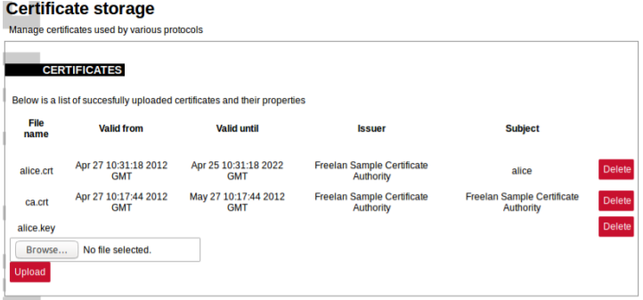](https://wiki.elseta.com/uploads/images/gallery/2021-12/image-1638366685126.png)
To get more details about how one could use TLS for Protocol Hub protocols please check section Excel configuration format.
To find out more about why certificates help keep device secure please check section Cyber security or check X.509 and RFC 5755 standard.# 25 Cyber security
WCC Lite is based on OpenWRT operating system. OpenWrt is described as a Linux distribution for embedded devices. WCC Lite has same functionality as Linux OS including user management.
Basic configuration on WCC Lite can be done using web based frontend. More advanced configuration is available over terminal interface. For secure web access, WCC Lite can be accessed via HTTPS (TLS) instead of the unencrypted HTTP protocol. You can use openssl utility to generate your own certificate authority and certificates to be used on web interface. Certificates can also be named or placed in whatever directory you wish by editing /etc/lighttpd/lighttpd.conf.
Terminal is accessible over Telnet or SSH. For security reasons we strongly recommend to use SSH. SSH, also known as Secure Socket Shell, is a network protocol that provides administrators with a secure way to access a remote computer. SSH also refers to the suite of utilities that implement the protocol. Secure shell provides strong authentication and secure encrypted data communications between two computers connecting over an insecure network such as the Internet. SSH is widely used by network administrators for managing systems and applications remotely, allowing them to log in to another computer over a network, execute commands and move files from one computer to another.
### User rights
Depending on the user name, different rights are defined: admin is generally entitled to make changes while user does not have any editing permissions, the relevant buttons are disabled. User can be assigned to one of fifteen user groups that can access different amounts of device parameters. Highest (fifteenth) permision level grants the same permission as root user has. User group rights can be edited to give more rights or restrictions, except for highest (15th) level.
#### User management and rights authentication
WCC Lite provides different authentication mechanisms:
- Authentication via locally stored credentials. In this scenario all users, passwords and
permissions are encrypted and stored in internal WCC Lite storage.
- Authentication via external RADIUS Server. In this scenario all users, passwords and
permissions (profiles) are defined in remote RADIUS Server. Login into WCC Lite is available
only if RADIUS Server will grant authentication and will provide user profile with user rights on
that device (more detailed description below). This also means that a password for such user
cannot be changed remotely.
- Authentication via external RADIUS Server with fallback option. In this scenario users will be
authenticated via RADIUS server. If server fails to respond (configured timeout is passed) WCC
will use locally stored credentials. Fallback options are selected with PAM configuration.
By default only authentication via locally stored credentials is allowed. For authentication via external RADIUS server a user should at first enable RADIUS process and configure at least one server.
#### Locally stored credentials management
Device has predefined default users like *root* and *user.*
*Screen containing all users*
[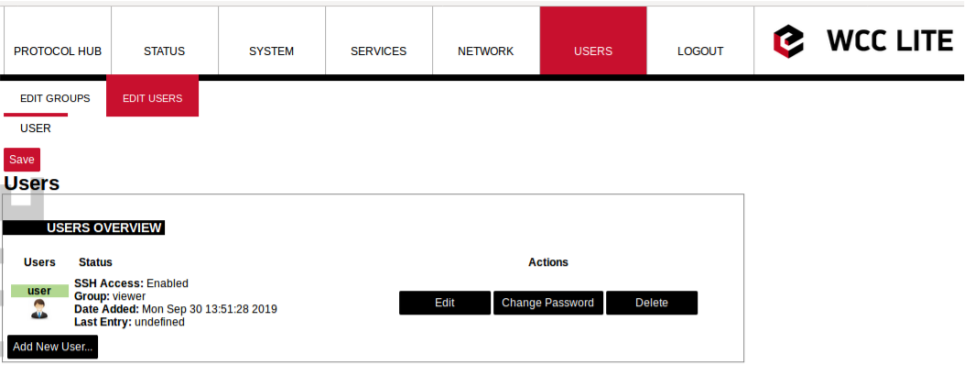](https://wiki.elseta.com/uploads/images/gallery/2021-12/image-1638367451931.png)
Screen for new user configuration
[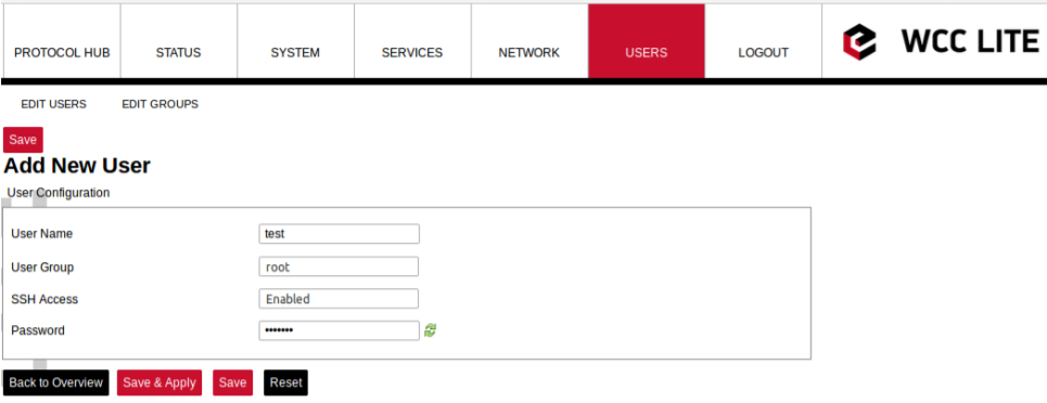](https://wiki.elseta.com/uploads/images/gallery/2021-12/image-1638367486607.png)
**root** user has full permission set to connect to WCC Lite over web interface and SSH or Telnet. This user is default user on WCC Lite and cannot be deleted. However, it is highly advised to change the default password to a different one less susceptible for attacks.
**user** is limited user on system and can’t get root rights. A default password for access via commandline interface and web interface is wcclite. It is advised to change this password to increase a level of security.
System allows customer to set up even more users with well known commands like *adduser, passwd* and *userdel.* More users can also be added or edited via web interface as shown in the figures above. User should enter user name, user groups for which the user should belong (the group must be preconfigured first), SSH access permision as well as password. When editing user settings, only *User Group* and *SSH Access* permission can be changed. To change user password, *Change Password* button should be pressed as seen in figure above to lead user to a screen seen in the figure below.
Changing user password
[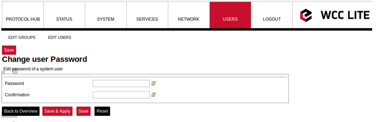](https://wiki.elseta.com/uploads/images/gallery/2021-12/image-1638367819194.png)
A user needs to be assigned to **root** group for admin rights and have root access
It should be noted that assigning user to a root group only gives complete authority over web interface. Permissions for a commandline interface should be given by a root user via commandline interface.
Following commands may be used in comamnd line interface for user control:
**adduser** - create a new user or update default new user information
When invoked without the **-D** option, the *adduser* command creates a new user account using the values specified on the command line plus the default values from the system. Depending on command line options, the useradd command will update system files and may also create the new user’s home directory and copy initial files.
**passwd** - change user password
The *passwd* command changes passwords for user accounts. A normal user may only change the password for his/her own account, while the superuser may change the password for any account. *passwd* also changes the account or associated password validity period.
**deluser** - delete a user account and related files
The *deluser* command modifies the system account files, deleting all entries that refer to the user name LOGIN. The named user must exist.
If a user intends to use newly created user account via both commandline interface and web interface he should create and delete users via web interface and not using adduser and deluser commands as they don’t create uci entries.
For more information about controlling users via command line interface one should refer to Linux documentation
#### Authentication via external service
WCC Lite support external authentification via RADIUS service. Remote Authentication DialIn User Service (RADIUS) is a networking protocol that provides centralized Authentication, Authorization, and Accounting (AAA or Triple A) management for users who connect and use a network service. RADIUS is a client/server protocol that runs in the application layer, and can use either TCP or UDP as transport. Network access servers, the gateways that control access to a network, usually contain a RADIUS client component that communicates with the RADIUS server. RADIUS is often the backend of choice for 802.1X authentication as well. The RADIUS server is usually a background process running on a UNIX or Microsoft Windows server. In WCC Lite RADIUS Client is implemented since WCC Lite software version v1.2.4. The user sends a request to a WCC Lite to gain access to get access using access credentials posted in an HTTP/HTTPS WCCLite web login form
This request includes access credentials, typically in the form of username and password. Additionally, the request may contain other information which the Device knows about the user, such as its network address or information regarding the user’s physical point of attachment to the device. The RADIUS server checks that the information is correct using authentication schemes such as PAP, CHAP or EAP. The user’s proof of identification is verified, along with, optionally, other information related to the request, such as the user’s network address, account status, and specific network service access privileges. Historically, RADIUS servers checked the user’s information against a locally stored flat file database. Modern RADIUS servers can do this, or can refer to external sources—commonly SQL, Kerberos, LDAP, or Active Directory servers—to verify the user’s credentials. The RADIUS server then returns one of two responses to the WCC Lite:
1. **Access-Reject** - The user is unconditionally denied access to all requested resources. Reasons may include failure to provide proof of identification or an unknown or inactive user account.
2. **Access-Accept** - The user is granted access. Once the user is authenticated, the RADIUS server will periodically check if the user is authorized to use the service requested. A given user may be allowed to get admin rights or user rights depending on permissions set on RADIUS Server. Again, this information may be stored locally on the RADIUS server, or may be looked up in an external source such as LDAP or Active Directory.
To use this mechanism a RADIUS server must be configured. The parameter Radius Authentication must be Enabled on WCC Lite.
As of firmware version 1.2.13, the RADIUS service is disabled by default. The service can be enabled at System->Startup.
If the RADIUS authentication is enabled, WCC Lite uses the RADIUS server IP address and the RADIUS shared secret key for communication with External RADIUS Server. After entering the login credentials and login attempt, WCC Lite sends these credentials to the RADIUS server for authentication. If the RADIUS server is available, it compares the login credentials:
- If the comparison is successful, the RADIUS server returns the specific user role and Access-Accept;
- If the login credentials are invalid, Radius Server returns Access-Reject and the logon fails.
- If the RADIUS server is not available and fallback option is disabled login into WCC Lite will
be imposible. If RADIUS server is not available and timeout occurs, login will be attempted via
local login credentials.
*Enabled:* Enables or disables this server.
*Hostname/IP:* Hostname or IP address of RADIUS server.
*Timeout:* Timeout in seconds to wait for server response.
*Shared* secret: Key shared between RADIUS server and RADIUS client.
*Add:* Adds auxiliary (backup) server.
#### Audit Log
WCC Lite OS with version >1.2.0 has integrated Audit logging for important events such as:
- Login/logout.
- Wrong password attempts to login into system.
- Device boot event, when system was started.
- Device reboot/halt event.
- Configuration changes.
- Firmware changes.
- Date and time changes in system (excluding automatic system time updates over NTP or IEC 60870510x protocol)
Enabling external system log server setup in System properties > Logging is recomended. System stores logs in RAM memory by default due to limited flash storage. Rebooting or powering off the device will result in loss of log history.
#### Secure your device’s access
There are some possibilities to grant access to the device (or to any PC/Server):
1. ask for nothing: anybody who can establish a connection gets access
2. ask for username and password on an unsecured connection (e.g. telnet)
3. ask for username and password on an encrypted connection (e.g. SSH) (e.g. by following
firstlogin)
4. ask for username and merely a signature instead of a password (e.g. SSH with
signature.authentication)
If you ask for username/password, an attacker has to guess the combination. If you use an unencrypted connection, he could eavesdrop on you and obtain them.
If you use an encrypted connection, any eavesdropper would have to decrypt the packets first. This is always possible. How long it takes to decrypt the content, depends on the algorithm and key length you used.
Also, as long as an attacker has network access to the console, he can always run a bruteforce attack to find out username and password. He does not have to do that himself: he can let his computer(s) do the guessing. To render this option improbable or even impossible you can:
- not offer access from the Internet at all, or restrict it to certain IP addresses or IP address ranges
- by letting the SSH server dropbear and the webServer lighttpd not listen on theexternal/WAN port
- by blocking incoming connections to those ports (TCP 22, 80 and 443 by default) in yourfirewall
- make it more difficult to guess:
- don’t use the username root
- don’t use a weak password with 8 or less characters
- don’t let the SSH server dropbear listen on the default port (22)
- use the combination of:
- username different than root
- tell dropbear to listen on a random port (should be >1024): **System > Administration >Dropbear Instance > Port**
- public key authentication. Your public keys can be specified in **Administation > System > SSHkeys**. An older guide to DropBear SSH public key authentication has detailed information on generating SSH keypairs which include the public key(s) you should upload to your configuration.
### Groups rights
1.
If user is logged on via external server, its authentification level is acquired. As no direct mapping to existing users is used, authentification levels are a way to grant proper permissions for external users. WCC Lite uses a CISCOlike authentification system, meaning that there are fifteen different permission set level settings, of which the first 14 can be configured to enable or disable View and Edit permissions
#### SSH Access
SSH Access of WCC Lite is made by Dropbear software package. To extend the basic functionality, Pluggable Authentification Module (PAM) for RADIUS is used. This enables user to add his own authentification modules as long as they are properly configured.
Fifteen levels of authorization are mapped for SSH access, meaning that user should be able to access SSH with credentials used to log into web interface. However, one should note that permissions in command line interface are not configurable via web interface. This means that first fourteen levels are restricted to basic permissions made my creating group by default. Highest level
user has all the permissions root user has.
If a user intends to change permissions for user groups, it should be done via command line interfaces. It is only advised for advanced users.
#### Web interface permissions
Fifteen levels of authorization permission are mapped for web interface access, meaning that user should be able to access web interface with credentials used to log into command line interface. User assigned to a highest authorization level group is able to access every possible screen therefore this groups cannot be edited.
Figure below shows a screen containing already existing groups in a device. Pressing *Add New Group...* guides user to an *Edit group* screen, with *Edit* and *Delete* buttons respectively user can Edit and Delete configuration of a given user group.
Screen showing existing user groups
[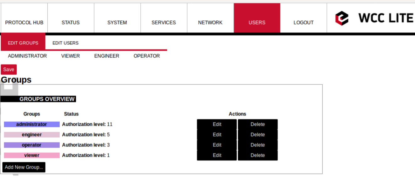](https://wiki.elseta.com/uploads/images/gallery/2021-12/image-1638369614131.png)
Screen for user group editing
[](https://wiki.elseta.com/uploads/images/gallery/2021-12/image-1638369707688.png)
Edit group screen for an individual group can be seen in Figure above. Group name doesn’t have any specific purpose for RADIUS, but it enables naming groups with words most meaningful for a given context. Access level values can only be integers between 1 and 14, other values will result in an error messages; only unconfigured levels are shown in a dropdown list when configuring. Other fields are dedicated for an individual menu configuration. To add more first level menus user should select from a dropdown list at the bottom named *–Additional Field–* and press Add.
Permissions for web interface are split into to parts: *View* and *Edit.*
*View* permissions can be assigned to second level menus meaning that only allowed subtabs are shown for a user. Selecting *View* checkbox show more parameters containing all the subtabs (submenus). If a user can access a given screen, it means all of the actions in that screen are available to be executed. Therefore, if a user with a lot of restrictions shouldn’t, for example, import Excel configuration to WCC Lite, a tab containing this action (*Protocol Hub>Configuration*) should be disabled in his groups' configuration.
*Edit* permissions can be assigned to first level menus meaning that if this permission is given, every configuration in the first level menu can be saved and applied succesfully
### Conformance to IEC 62351 standard
IEC 62351 is a standard developed by WG15 of IEC TC57. This is developed for handling the security of TC 57 series of protocols including IEC 608705 series, IEC 608706 series, IEC 61850 series, IEC 61970 series and IEC 61968 series. The different security objectives include authentication of data transfer through digital signatures, ensuring only authenticated access, prevention of
eavesdropping, prevention of playback and spoofing, and intrusion detection.
Conformance to IEC 62351 standard of WCC Lite devices is described in a table below.
Conformance to IEC 62351 standard
| **Standard** | **Description** | **Topic** | **Implemented** | **Version** |
| IEC 62351-3
| Security for any profiles including TCP/IP | TLS Encryption | Yes | >=1.3 |
| Node Authentication by means of X.509 certificates | Yes | >=1.3 |
| Message Authentication | Yes | >=1.3 |
| IEC 62351-4 | Security for any
profiles including
MMS | Authentication for MMS | Yes | >=1.5 |
|
| TLS (RFC 2246)is inserted between RFC 1006 & RFC 793 to provide transport layer
security | Yes | >=1.5 |
| IEC 62351-5 | Security for any
profiles including
IEC 608705 | TLS for TCP/IP profiles and encryption for serial profiles | No |
|
| IEC 62351-6 | Security for IEC
61850 profiles | VLAN use is made as mandatory for GOOSE | No |
|
| RFC 2030 to be used for SNTP | No |
|
| IEC 62351-7 | Security through
network and system
management | Defines Management Information Base (MIBs) that are specific for the power industry, to handle network and system
management through SNMP based methods | No |
|
| IEC 62351-8 | Role-based access control | Covers the access control of users and automated agents to data objects in power systems by means of rolebased access
control (RBAC) | Yes | >=1.2.6 |
| IEC 62351-9 | Key
Management | Describes the correct and safe usage of safety-critical parameters, e.g. passwords,
encryption keys. | No |
|
| Covers the whole life cycle of cryptographic information (enrolment, creation,
distribution, installation, usage, storage and removal) | No |
|
| Methods for algorithms using asymmetric cryptography | No |
|
| A secure distribution mechanism based on GDOI and the IKEv2 protocol is
presented for the usage of symmetric keys, e.g. session keys | No |
|
| IEC 62351-10 | Security Architecture | Explanation of security architectures for the entire IT infrastructure | No |
|
| Identifying critical points of the communication architecture, e.g. substation control center, substation automation | No |
|
| Appropriate mechanisms security requirements, e.g. data encryption, user authentication | No |
|
| Applicability of wellproven standards from the IT domain, e.g. VPN tunnel, secure FTP,
HTTPS | No |
|
| IEC 62351-11 | Security for XML Files | Embedding of the original XML content into an XML container | No |
|
| Date of issue and access control for XML data | No |
|
| X.509 signature for authenticity of XML data | No |
|
| Optional data encryption | No |
|