14 IEC 60870-5-10X
- 14.1 Introduction
- 14.2 IEC 60870-5-101 Master
- 14.3 IEC 60870-5-101 Slave
- 14.4 IEC 60870-5-103 Master
- 14.5 IEC 60870-5-104 Master
- 14.6 IEC 60870-5-104 Slave
14.1 Introduction
IEC 60870 part 5 is one of the IEC 60870 set of standards which define systems used for telecontrol (supervisory control and data acquisition) in electrical engineering and power system automation applications. Part 5 provides a communication profile for sending basic telecontrol messages between two systems, which uses permanent directly connected data circuits between the systems. The IEC Technical Committee 57 (Working Group 03) has developed a protocol standard for telecontrol, teleprotection, and associated telecommunications for electric power systems. The result of this work is IEC 60870-5. Five documents specify the base IEC 60870-5:
- IEC 60870-5-1 Transmission Frame Formats
- IEC 60870-5-2 Data Link Transmission Services
- IEC 60870-5-3 General Structure of Application Data
- IEC 60870-5-4 Definition and Coding of Information Elements
- IEC 60870-5-5 Basic Application Functions
- IEC 60870-5-6 Guidelines for conformance testing for the IEC 60870-5 companion standards
- IEC TS 60870-5-7 Security extensions to IEC 60870-5-101 and IEC 60870-5-104 protocols (applying IEC 62351)
The IEC Technical Committee 57 has also generated companion standards:
- IEC 60870-5-101 Transmission Protocols - companion standards especially for basic telecontrol tasks
- IEC 60870-5-102 Transmission Protocols - Companion standard for the transmission of integrated totals in electric power systems (this standard is not widely used)
- IEC 60870-5-103 Transmission Protocols - Companion standard for the informative interface of protection equipment
- IEC 60870-5-104 Transmission Protocols - Network access for IEC 60870-5-101 using standard transport profiles
- IEC TS 60870-5-601 Transmission protocols - Conformance test cases for the IEC 60870-5-101 companion standard
- IEC TS 60870-5-604 Conformance test cases for the IEC 60870-5-104 companion standard
IEC 60870-5-101/102/103/104 are companion standards generated for basic telecontrol tasks, the transmission of integrated totals, data exchange from protection equipment & network access of IEC101 respectively.
Source: https://en.wikipedia.org/wiki/IEC_60870-5
14.2 IEC 60870-5-101 Master
The IEC 60870-5-101 protocol is a companion standard for power system monitoring, control associated communications for telecontrol, teleprotection and associated telecommunications for electric power systems. Standard IEC 60870-5-101 was prepared by IEC Technical Committee 57 (Power system control and associated communications).
Standard IEC 60870-5-101 defines an Application Service Data Unit (ASDU Figure below). In ASDU there is an ASDU identifier (with the type of ASDU in it) and information objects.
IEC 60870-5-101 ASDU structure
Common Address of ASDU Defines the stations' address and can be configured in Devices asdu_address field for source and Signals common_address field for the destination.
Information Object Address Used as destination object address in the control direction and as source object address in the monitor direction can be configured in the Signals info_address field.
Standard IEC 60870-5-101 transmission frames are separated into 3 different types: frame with variable length, frame with fixed length, and single control characters
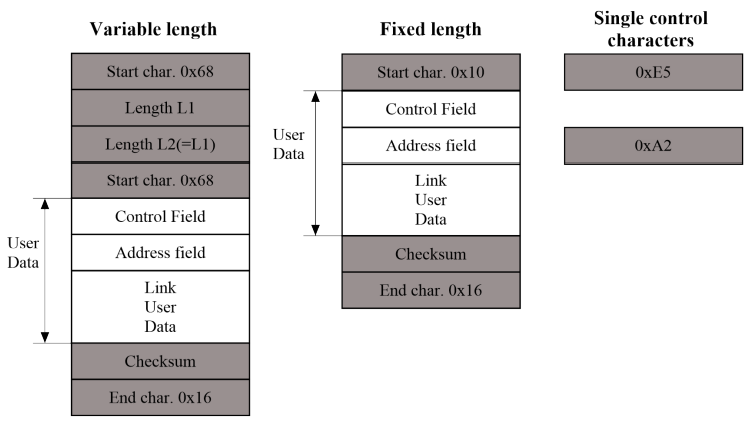
IEC 60870-5-101 ASDU structure
The control field provides information about the message direction, type of service, and checksum.
The address field specifies the link address which points to the message's destination. WCC Lite supports IEC 60870-5-101 Master protocol over a serial link (according to EIA RS485). Its full functionality list can be found in an IEC 60870-5-101 PID Interoperability List which can be downloaded separately from this user manual.
Configuring datapoints (master)
The IEC 60870-5-101 Master in WCC Lite has to be configured in Excel. This configuration contains two Excel sheets where parameters must be filled in Devices and Signals.
IEC 60870-5-101 master parameters for Devices tab
| Parameter |
Type |
Description |
Required |
Default value (when not specified) |
Range |
|
|
Min |
Max |
|||||
|
name |
string |
User-friendly name for a device |
Yes | |||
|
description |
string |
Description of a device |
No | |||
|
device_alias |
string |
Alphanumeric string to identify a device |
Yes | |||
| enable | boolean |
Enabling/disabling of a device |
No | 1 | 0 | 1 |
| protocol | string |
Protocol to be used |
Yes | IEC 60870-5-101 master | ||
| device |
string |
Communication port |
Yes |
|
PORT1 |
PORT2 |
| baudrate | integer |
Communication speed (bauds/s) |
No |
9600 |
600, 1200, 2400, 4800, 9600, 19200, 38400, 57600, 115200 |
|
| databits | integer |
Data bit count for communication |
No |
8 |
6 |
9 |
| stopbits | integer |
Stop bit count for communication |
No |
1 |
1 |
2 |
| parity |
string |
Communication parity option |
No |
none |
none, even, odd |
|
| flowcontrol |
string |
Number of requests, before the link is considered lost (device status signals are changed) and reconnect attempt will be issued |
No |
none |
none |
|
| link_address | integer | Destination address when in transmit and source address when broadcasting | Yes | 0 | 65535 | |
| link_size | integer | Link address size in bytes | No | 1 | 1 | 2 |
| asdu_address | integer | Application Service Data Unit address | Yes | 0 | 65535 | |
| asdu_size | integer | Common address size in bytes | No | 1 | 1 | 2 |
| ioa_size | integer | Information object address (IOA) size in bytes | No | 2 | 1 | 3 |
| cot_size | integer | Cause of transmission (COT) size in bytes | No | 1 | 1 | 2 |
| time_sync_interval_sec | integer |
Defines how often (in seconds) a slave will request time synchronization. If greater than 0 – slave will request synchronizations and will reset the timer if the master did it earlier. If 0 – slave won’t request timesyncs, but will allow them. If 1 – time syncs are not supported, all time sync requests will be dropped. |
No | 60 | ||
| gi_interval_sec | integer | The time frame between General Interrogation requests in seconds if 0 requests are disabled | No | 300 |
|
|
| scan_rate_ms | integer |
Polling interval in milliseconds. The time frame between two telegrams from the master |
No | 100 | ||
| timeout_ms | integer |
Response timeout in milliseconds |
No |
1000 |
|
|
| retry_count | integer |
Number of retries of failed requests before announcing that the device is in Error state |
No | 1 | ||
IEC 60870-5-101 master parameters for Signals tab
| Parameter |
Type |
Description |
Required |
Default value (when not specified) |
Range |
|
|
Min |
Max |
|||||
|
signal_name |
string |
User-friendly signal name |
Yes | |||
|
device_alias |
string |
Alphanumeric string to identify a device |
Yes | |||
|
signal_alias |
string |
Unique alphanumeric name of the signal to be used |
Yes | |||
|
source_device_alias |
string |
device_alias of a source device |
For commands | |||
|
source_signal_alias |
string |
signal_alias of a source signal |
For commands |
|||
| enable | boolean |
Enabling/disabling of an individual signal |
No | 1 | 0 | 1 |
|
log |
integer |
Allow signal to be logged. If the log is 0 signal will not be logged. If the log is more than 0 signal will be logged |
No | 0 | ||
| gi | boolean | Including/excluding (1 or 0) signals from General Interrogation | No | 0 | 0 | 1 |
| common_address | integer | Address of a destination device | No | 1 | ||
| info_address | integer | Information object address | Yes | |||
| data_type | integer | ASDU type identifier | Yes |
1, 2, 3, 4, 5, 6, 9, 10, 11, 12, 13, 14, 30, 31, 32, 34, 35, 36, 45, 46, 47, 48, 49, 50
|
||
| periodic_update_ms | integer | Signal value is published periodically according to the value set. | No |
|
||
Device status signals
IEC 60870-5-101 has an additional signal which can be configured to show communication status. It is used to indicate if the slave device has disconnected from the master (WCC Lite). To configure such signal for IEC 60870-5-101 protocol, job_todo and tag_job_todo fields with string values are required. For IEC 60870-5-101 master required parameters for the status signal will be: signal_name device_alias, signal_alias, common_address, info_address, data_type, job_todo and tag_job_todo. Job_todo value must be device_status and for tag_job_todo there are 4 variations: communication_status, device_running, device_error, uknown_error. Each signal has 4 possible values and is based on the same logic. If the signal returns the value of 0, it means an unknown error has appeared, 1 – the device or protocol connection is on and working properly, 2 – the device is off or the protocol is disconnected, and 3 – the error or service is down.
Debugging an IEC 60870-5-101 Master application
If the configuration for IEC 60870-5-101 devices is set up, a handler for the protocol will start automatically. If the configuration is missing parameters or contains errors, the protocol will not start. It is done intentionally to decrease unnecessary memory usage.
If IEC 60870-5-101 does not work properly (e.g. no communication between devices, data is corrupted, etc.), a user can launch a debug session from the command line interface and find out why the link is not functioning properly. To launch a debugging session, a user should stop the iec101-master process and run the iec101-master command with respective flags as shown in the table below.
Procedure for IEC 60870-5-101 master service debugging:
- Step 1: Service must be stopped by entering the following command into the WCC Lite:
/etc/init.d/iec101-master stop - Step 2: After the service is stopped it must be started with the preferred configuration file (JSON files found in /etc/ folder) and a debug level 7:
Additional output forming options are described here: Command line arguments.iec101-master -c /etc/iec101-master/ttyPORT1.json -d7 - Step 3: Once the problem is diagnosed normal operations can be resumed with the following command:
/etc/init.d/iec101-master start
IEC 60870-5-101 command line debugging options
-h [ –help ] Display help information
-V [ –version ] Show version
-d<debug level> Set debugging level
-c [ –config ] Config path
-e [ –redis ] Show redis debug information
14.3 IEC 60870-5-101 Slave
Configuring datapoints (slave)
The IEC 60870-5-101 Slave in WCC Lite has to be configured in Excel. This configuration contains two Excel sheets where parameters must be filled in Devices and Signals.
IEC 60870-5-101 slave parameters for Devices tab
| Parameter |
Type |
Description |
Required |
Default value (when not specified) |
Range |
|
|
Min |
Max |
|||||
|
name |
string |
User-friendly name for a device |
Yes | |||
|
description |
string |
Description of a device |
No | |||
|
device_alias |
string |
Alphanumeric string to identify a device |
Yes | |||
| enable | boolean |
Enabling/disabling of a device |
No | 1 | 0 | 1 |
| protocol | string |
Protocol to be used |
Yes | IEC 60870-5-101 slave | ||
| device |
string |
Communication port |
Yes |
|
PORT1 |
PORT2 |
| baudrate | integer |
Communication speed (bauds/s) |
No |
9600 |
300, 600, 1200, 2400, 4800, 9600, 19200, 38400, 57600, 115200 |
|
| databits | integer |
Data bit count for communication |
No |
8 |
6 |
9 |
| stopbits | integer |
Stop bit count for communication |
No |
1 |
1 |
2 |
| parity |
string |
Communication parity option |
No |
none |
none, even, odd |
|
| flowcontrol |
string |
Number of requests, before the link is considered lost (device status signals are changed) and reconnect attempt will be issued |
No |
none |
none |
|
| link_address | integer | Destination address when in transmit and source address when broadcasting | Yes | 0 | 65535 | |
| link_size | integer | Link address size in bytes | No | 1 | 1 | 2 |
| asdu_size | integer | Common address size in bytes | No | 1 | 1 | 2 |
| ioa_size | integer | Information object address (IOA) size in bytes | No | 2 | 1 | 3 |
| cot_size | integer | Cause of transmission (COT) size in bytes | No | 1 | 1 | 2 |
| time_sync | boolean | Allow time synchronization, 1 to enable and 0 to disable | Yes | 0 | 1 | |
| message_size | integer | Maximum length of a message | No | 253 | 0 | 255 |
| cache_size | integer | Maximum number of events to store in a buffer | No | 100 | 0 | 1000 |
| respond_delay | integer | Time in microseconds to wait before sending responses | No | 100 | 0 | 1000000 |
| single_byte_ack | boolean | Use single character acknowledge, 1 to enable and 0 to disable |
No |
0 | 0 | 1 |
| keep_alive_timeout | integer | Time interval in seconds before serial connection is considered offline |
No |
60 | ||
keep_alive_timeout timer is used for the connection tracker to display protocol status. This parameter does not affect protocol functionality and only tracks its status in the connection tracker.
IEC 60870-5-101 slave parameters for Signals tab
| Parameter |
Type |
Description |
Required |
Default value (when not specified) |
Range |
|
|
Min |
Max |
|||||
|
signal_name |
string |
User-friendly signal name |
Yes | |||
|
device_alias |
string |
Alphanumeric string to identify a device |
Yes | |||
|
signal_alias |
string |
Unique alphanumeric name of the signal to be Yes used |
Yes | |||
|
source_device_alias |
string |
device_alias of a source device |
For commands | |||
|
source_signal_alias |
string |
signal_alias of a source signal |
For commands | |||
| enable | boolean |
Enabling/disabling of an individual signal |
No | 1 | 0 | 1 |
|
log |
integer |
Allow signal to be logged. If the log is 0, the signal will not be logged. If the log is more than 0, the signal will be logged |
No | 0 | ||
| gi | boolean | Including/excluding (1 or 0) signals from General Interrogation | No | 0 | 0 | 1 |
| common_address | integer | Address of a destination device | Yes | |||
| info_address | integer | Information object address | Yes | |||
| data_type | integer | ASDU type identifier | Yes |
1, 2, 3, 4, 5, 6, 9, 10, 11, 12, 13, 14, 30, 31, 32, 34, 35, 36, 45, 46, 47, 48, 49, 50, 58, 59, 60, 61, 62, 63
|
||
| periodic_update_ms | integer | Signal value is published periodically according to the value set. | No | - |
-
|
|
Device status signals
IEC 60870-5-101 has an additional signal which can be configured to show communication status. It indicates if the master device has disconnected from the slave (WCC Lite). To configure such signal for IEC 60870-5-101 protocol, job_todo and tag_job_todo fields with string values are required. For IEC 60870-5-101 slave required parameters for status, signal will be signal_name device_alias, signal_alias, common_address, info_address, data_type, job_todo and tag_job_todo. Job_todo value must be device_status and for tag_job_todo there are 4 variations: communication_status, device_running, device_error, uknown_error. Each signal has 4 possible values and is based on the same logic. If the signal returns the value of 0, it means an unknown error has appeared, 1 – the device or protocol connection is on and working properly, 2 – the device is off or protocol is disconnected, and 3 – the error or service is down.
Debugging an IEC 60870-5-101 slave application
If the configuration for IEC 60870-5-101 devices is set up, the handler for the protocol will start automatically. If the configuration is missing parameters or contains errors, the protocol will not start. It is done intentionally to decrease unnecessary memory usage.
If IEC 60870-5-101 does not work properly (e.g. no communication between devices, data is corrupted, etc.), a user can launch a debug session from the command-line interface and find out why the link is not functioning properly. To launch a debugging session, a user should stop the iec101-slave process and run the iec101-slave command with respective flags as shown in the table below.
Procedure for IEC 60870-5-101 slave service debugging:
- Step 1: Service must be stopped by entering the following command into the WCC Lite:
/etc/init.d/iec101-slave stop - Step 2: After the service is stopped it must be started with the preferred configuration file (JSON
files found in /etc/ folder) and a debug level 7:
Additional output forming options are described here: Command line arguments.iec101-slave -c /etc/iec101-slave/ttyPORT1.json -d7 - Step 3: Once the problem is diagnosed normal operations can be resumed with the following
command:/etc/init.d/iec101-slave start
IEC 60870-5-101 command line debugging options
-h [ –help ] Display help information
-V [ –version ] Show version
-d<debug level> Set debugging level
-c [ –config ] Config path
-e [ –redis ] Show redis debug information
14.4 IEC 60870-5-103 Master
The IEC 60870-5-103 protocol is a companion standard for the informative interface of protection equipment. Standard IEC 60870-5-103 was prepared by IEC Technical Committee 57 (Power system control and associated communications). It is a companion standard for the basic standards in series IEC 60870-5:
Standard IEC 60870-5-103 defines communication between protection equipment and devices of a control system (supervisor or RTU) in a substation.
Standard IEC 60870-5-103 defines a multipoint communication protocol via exchanging information between a control system (supervisor or RTU) and one or more protection devices. The control system is the master and the protection devices are the slaves. Each slave is identified by a unique address between 1 and 254. Address 255 is reserved for broadcast frames.
IEC 60870-5-103 Master
Configuring datapoints
WCC Lite supports IEC 60870-5-103 Master protocol over a serial link (according to EIA RS-485). Its full functionality list can be found in an IEC 60870-5-103 PID Interoperability List.
The IEC 60870-5-103 Master in WCC Lite has to be configured in Excel. This configuration contains two Excel sheets where parameters must be filled in - Devices and Signals.
IEC 60870-5-103 parameters for Devices tab
| Parameter |
Type |
Description |
Required |
Default value (when not specified) |
Range |
|
|
Min |
Max |
|||||
|
name |
string |
User-friendly name for a device |
Yes | |||
|
description |
string |
Description of a device |
No | |||
|
device_alias |
string |
Alphanumeric string to identify a device |
Yes | |||
| enable | boolean |
Enabling/disabling of a device |
No | 1 | 0 | 1 |
| protocol | string |
Protocol to be used |
Yes | IEC 60870-5-103 master | ||
| device |
string |
Communication port |
Yes |
|
PORT1 |
PORT2 |
| baudrate | integer |
Communication speed (bauds/s) |
No |
9600 |
600, 1200, 2400, 4800, 9600, 19200, 38400, 57600, 115200 |
|
| databits | integer |
Data bit count for communication |
No |
8 |
8 |
|
| stopbits | integer |
Stop bit count for communication |
No |
1 |
1 |
2 |
| parity |
string |
Communication parity option |
No |
none |
none, even, odd |
|
| flowcontrol |
string |
Number of requests, before the link is considered lost (device status signals are changed) and reconnect attempt will be issued |
No |
none |
none |
|
| link_address | integer | Destination address when in transmit and source address when broadcasting | Yes | 0 | 65535 | |
| asdu_address | integer | Application Service Data Unit address | Yes | 0 | 65535 | |
| time_sync_interval_sec | integer |
The time frame between Time Synchronization requests in seconds. If 0 requests are disabled. |
No | 60 | ||
| gi_interval_sec | integer | The time frame between General Interrogation requests in seconds if 0 requests are disabled | No | 300 |
|
|
| scan_rate_ms | integer |
Polling interval in milliseconds. The time frame between two telegrams from the master. |
No | 100 | ||
| timeout_ms | integer |
Response timeout in milliseconds |
No |
1000 |
|
|
| serial_delay | integer | Communication device’s serial delay in milliseconds. Time frame in which the master station is not TX’ing after the last RX byte | No | 50 | ||
| retry_count | integer |
Number of retries of failed requests before announcing that the device is in Error state |
No | 3 | ||
| retry_delay_ms | integer | Time before the next retry in milliseconds | No | 500 | ||
| reset_command_type | string | The user can choose the reset command type between FCB and CU. | No | FCB | FCB | CU |
IEC 60870-5-103 master parameters for Signals tab
| Parameter |
Type |
Description |
Required |
Default value (when not specified) |
Range |
|
|
Min |
Max |
|||||
|
signal_name |
string |
User-friendly signal name |
Yes | |||
|
device_alias |
string |
Alphanumeric string to identify a device |
Yes | |||
|
signal_alias |
string |
Unique alphanumeric name of the signal to be Yes used |
Yes | |||
|
source_device_alias |
string |
device_alias of a source device |
For commands | |||
|
source_signal_alias |
string |
signal_alias of a source signal |
For commands |
|||
| enable | boolean |
Enabling/disabling of an individual signal |
No | 1 | 0 | 1 |
|
log |
integer |
Allow signal to be logged. If the log is 0, the signal will not be logged. If the log is more than 0 signal will be logged |
No | 0 | ||
| gi | boolean | Including/excluding (1 or 0) signals from General Interrogation | No | 0 | 0 | 1 |
| common_address | integer | Address of a destination device | Yes | |||
| function | integer | Function number | No | 0 | ||
| info_address | integer | Information object address | Yes | |||
| info_number | integer | Information number | Yes | |||
| data_type | integer | ASDU type identifier | No | 0 |
0, 1, 2, 3, 4, 9, 20
|
|
| fleeting | boolean | Mark the signal as a fleeting type (1 or 0). Fleeting signals have to go to DPI::OFF after a defined time | No | 0 | 1 | |
| normalise_time_ms | integer | Time in milliseconds between station receiving DPI::ON and automatically switching to DPI::OFF | If fleeting is used | 100 | ||
| periodic_update_ms | integer | Signal value is published periodically according to the value set. | No | - | - | - |
Device status signals
IEC 60870-5-103 has an additional signal which can be configured to show communication status. It indicates if the slave device has disconnected from the master (WCC Lite). To configure such signal for IEC 60870-5-103 protocol, job_todo and tag_job_todo fields with string values are required. For IEC 60870-5-103 master required parameters for the status signal will be: signal_name device_alias, signal_alias, common_address, info_address, info_number, job_todo and tag_job_todo. Job_todo value must be device_status and for tag_job_todo there are 4 variations: communication_status, device_running, device_error, uknown_error. Each signal has 4 possible values and is based on the same logic. If the signal returns the value of 0, it means an unknown error has appeared, 1 – device or protocol connection is on and working properly, 2 – device is off or protocol is disconnected, 3 – error or service is down.
Debugging an IEC 60870-5-103 Master application
If the configuration for IEC 60870-5-103 devices is set up, the handler for the protocol will start automatically. If a configuration is missing parameters or contains errors, the protocol will not start. It is done intentionally to decrease unnecessary memory usage.
If IEC 60870-5-103 does not work properly (e.g. no communication between devices, data is corrupted, etc.), a user can launch a debug session from the command-line interface and find out why the link is not functioning properly or use WCC Utility to do that.
To launch a debugging session, a user should stop the iec103-master process and run the iec103-master command with respective flags.
- Step 1: Service must be stopped by entering the following command into the WCC Lite:
/etc/init.d/iec103-master stop - Step 2: After the service is stopped it must be started with the preferred configuration file (JSON
files found in /etc/ folder) and a debug level 7:iec103-master -c /etc/iec103-master/ttyPORT1.json -d7 - Step 3: Once the problem is diagnosed normal operations can be resumed with the following command:
/etc/init.d/iec103-master start
IEC 60870-5-103 command line debugging options
-h [ –help ] Display help information
-V [ –version ] Show version
-d<debug level> Set debugging level
-c [ –config ] Config path
-e [ –redis ] Show redis debug information
14.5 IEC 60870-5-104 Master
IEC 60870-5-104 protocol (in short IEC 104) is a part of IEC Telecontrol Equipment and Systems Standard IEC 60870-5 that provides a communication profile for sending basic telecontrol messages between two systems in electrical engineering and power system automation. Telecontrol means transmitting supervisory data and data acquisition requests for controlling power transmission grids.
IEC 104 provides network access to IEC 60870-5-101 (in short IEC 101) using standard transport profiles. In simple terms, it delivers IEC 101 messages as application data (L7) over TCP, usually port 2404. IEC 104 enables communication between the control station and a substation via a standard TCP/IP network. The communication is based on the client-server model.
To set up TLS connection for both IEC104 Master and Slave, refer to sections Excel configuration and Certificates. All keys and certificates should be provided in the PEM format.
If no configuration is set up, IEC104 Master and Slave services are not started.
Configuring IEC 104 Master data points
To use IEC 60870-5-104 Master in WCC Lite, it has to be configured via an Excel configuration. This configuration contains two Excel sheets where parameters have to be filled in Devices and Signals.
IEC 60870-5-104 Master parameters for Devices tab
| Parameter |
Type |
Description |
Required |
Default value (when not specified) |
Range |
|
|
Min |
Max |
|||||
|
name |
string |
User-friendly name for a device |
Yes | |||
|
description |
string |
Description of a device |
No | |||
|
device_alias |
string |
Alphanumeric string to identify a device |
Yes | |||
| enable | boolean |
Enabling/disabling of a device |
No | 1 | 0 | 1 |
| protocol | string |
Protocol to be used |
Yes | IEC 60870-5-104 master | ||
| asdu_address | integer | Application Service Data Unit address | Yes | 0 | 65535 | |
| asdu_size | integer | Common address size in bytes | No | 2 | 1 | 2 |
| time_sync_interval_sec | integer | The time frame between Time Synchronization requests in seconds |
No | 60 | ||
| gi_interval_sec | integer |
The time frame between General Interrogation requests in seconds. If 0 requests are disabled |
No | 300 |
|
|
| port | integer | TCP port | Yes | 0 | 65535 | |
| ioa_size | integer | Information object address (IOA) size in bytes | No | 3 | 1 | 3 |
| swt | integer | Send window (k) | Yes |
|||
| rwt | integer | Receive window (w) | Yes |
|||
| cot_size | integer | Cause of transmission (COT) size in bytes | No | 2 | 1 | 3 |
| host | string | Host IP address (ipv4) | Yes | |||
|
t1* |
integer | Acknowledge timeout t1 (sec) | No | 15 | 1 | 255 |
| t2* | integer | Connection ACKRSN clock t2 (sec) | No | 10 | 1 | 254 |
| t3* | integer | Connection TESTFR clock t3 (sec) | No | 20 | 1 |
172800
|
| originator | integer | Provides a means for a controlling station to explicitly identify itself | No | 0 | 0 | 255 |
* - t1, t2 and t3 parameters must meet the inequality: t2<t1<t3.
IEC 60870-5-104 Master parameters for Signals
| Parameter |
Type |
Description |
Required |
Default value (when not specified) |
Range |
|
|
Min |
Max |
|||||
|
signal_name |
string |
User-friendly signal name |
Yes | |||
|
device_alias |
string |
Alphanumeric string to identify a device |
Yes | |||
|
signal_alias |
string |
Unique alphanumeric name of the signal to be Yes used |
Yes | |||
|
source_device_alias |
string |
device_alias of a source device |
For commands | |||
|
source_signal_alias |
string |
signal_alias of a source signal |
For commands |
|||
| enable | boolean |
Enabling/disabling of an individual signal |
No | 1 | 0 | 1 |
|
log |
integer |
Allow signal to be logged. If the log is 0, the signal will not be logged. If the log is more than 0, the signal will be logged |
No | 0 | ||
| gi | boolean | Including/excluding (1 or 0) signals from General Interrogation | No | 0 | 0 | 1 |
| common_address | integer | Address of a destination device | Yes | |||
| function | integer | Function number | No | 0 | ||
| info_address | integer | Information object address | Yes | |||
| data_type | integer | ASDU type identifier | Yes |
1, 3, 5, 9, 11, 13, 21, 30, 31, 32, 34, 35, 36, 45, 46, 47, 48, 49, 50, 58, 59, 60, 61, 62, 63
|
||
| select_ms | integer | Time limit in milliseconds for command execution. Command selection has to be performed before execution if this parameter is specified. Direct command execution can be performed only if this field is left empty or set to zero. |
No | 0 | ||
| periodic_update_ms | integer | Signal value is published periodically according to the value set. | No | - | - | - |
Device status signals
IEC 60870-5-104 has an additional signal which can be configured to show communication status. It indicates if the slave device has disconnected from the master (WCC Lite). To configure such signal for IEC 60870-5-104 protocol, job_todo and tag_job_todo fields with string values are required. For IEC 60870-5-104 master required parameters for the status signal will be: signal_name device_alias, signal_alias, common_address, info_address, data_type, job_todo and tag_job_todo. Job_todo value must be device_status and for tag_job_todo there are 4 variations: communication_status, device_running, device_error, uknown_error. Each signal has 4 possible values and is based on the same logic. If the signal returns the value of 0, it means an unknown error has appeared, 1 – device or protocol connection is on and working properly, 2 – device is off or protocol is disconnected, 3 – error or service is down.
Debugging an IEC 60870-5-104 Master application
If the configuration for IEC 60870-5-104 devices is set up, the handler for the protocol will start automatically. If a configuration is missing parameters or contains errors, the protocol will not start. It is done intentionally to decrease unnecessary memory usage.
If IEC 60870-5-104 does not work properly (e.g. no communication between devices, data is corrupted, etc.), a user can launch a debug session from the command-line interface and find out why the link is not functioning properly or use WCC Utility to do that.
To launch a debugging session, a user should stop the iec104-master process and run the iec104-master command with respective flags.
- Step 1: Service must be stopped by entering the following command into the WCC Lite:
/etc/init.d/iec104-master stop - Step 2: After the service is stopped it must be started with the preferred configuration file (JSON
files found in /etc/ folder) and a debug level 7:iec104-master -c /etc/iec104-master/ttyPORT1.json -d7 - Step 3: Once the problem is diagnosed normal operations can be resumed with the following command:
/etc/init.d/iec104-master start
IEC 60870-5-104 command-line debugging options
-h [ –help ] Display help information
-V [ –version ] Show version
-d<debug level> Set debugging level
-c [ –config ] Config path
-e [ –redis ] Show redis message
14.6 IEC 60870-5-104 Slave
Since firmware version 1.8.3, multiple signals with different data types can have the same ioa address.
IEC 60870-5-104 Slave is designed not to lose data acquired from Master protocols. The data that arrives from Master protocols is stored in the cache. This data is checked every second to manage further data sending. The data that leaves IEC 60870-5-104 Slave has output caches. They’re built to provide switching between multiple sessions (redundant SCADA). If a new connection arrives, the old one is dropped, but data, that is stored in a cache, not sent and not confirmed by SCADA is transferred to the new connection.
Configuring IEC 104 Slave data points
To use IEC 60870-5-104 Slave in WCC Lite, it has to be configured via an Excel configuration. This configuration contains two Excel sheets where parameters have to be filled in Devices and Signals.
IEC 60870-5-104 Slave parameters for Devices tab
| Parameter |
Type |
Description |
Required |
Default value (when not specified) |
Range |
|
|
Min |
Max |
|||||
|
name |
string |
User-friendly name for a device |
Yes | |||
|
description |
string |
Description of a device |
No | |||
|
device_alias |
string |
Alphanumeric string to identify a device |
Yes | |||
| enable | boolean |
Enabling/disabling of a device |
No | 1 | 0 | 1 |
| protocol | string |
Protocol to be used |
Yes | IEC 60870-5-104 slave | ||
| asdu_size | integer | Common address size in bytes | No | 2 | 1 | 2 |
| time_sync | boolean | Enable/disable (1 or 0) time synchronization | Yes | |||
| port | integer | TCP port | No | 2404 | 0 | 65535 |
| ioa_size | integer | Information object address (IOA) size in bytes | No | 3 | 1 | 3 |
| swt | integer | Send window (SWT) | No | 12 | ||
| rwt | integer | Receive window (RWT) | No | 8 | ||
| cot_size | integer | Cause of transmission (COT) size in bytes | No | 2 | 1 | 3 |
| host | string | Space-separated remote host IP addresses (ipv4) | Yes | |||
| bind_address | string | Bind to local IP address (ipv4) | No | 0.0.0.0 | ||
|
t1 |
integer | Acknowledge timeout t1 (sec) | No | 15 | 1 | 255 |
| t2 | integer |
Connection ACKRSN clock t2 (sec), t2 should be less than t1 |
No | 10 | 1 | 254 |
| t3 | integer | Connection TESTFR clock t3 (sec) | No | 20 | 1 | 172800 |
| message_size | boolean | The maximum length of a message | No | 253 | 0 | 255 |
| cache_size | integer | Amount of data to be cached | No | 100 | 0 | 1000 |
| tls | boolean | Enable/disable the use of TLS | No | 0 | 0 | 1 |
| tls_local_certificate | string | Local certificate for TLS connection | Yes (for TLS) | |||
| tls_peer_certificate | string | Certificate authority file for TLS connection | No | |||
| tls_private_key | string | A file consisting of the private key for TLS connection | No | |||
| command_timeout_ms | integer | Time to execute a command before responding negatively. | No | 30000 | 0 | |
| command_age_ms | integer | The amount of time shift allowed for the command to still be executed. | No | 0 | 0 | |
IEC 60870-5-104 Slave parameters for Signals tab
| Parameter |
Type |
Description |
Required |
Default value (when not specified) |
Range |
|
|
Min |
Max |
|||||
|
signal_name |
string |
User-friendly signal name |
Yes | |||
|
device_alias |
string |
Alphanumeric string to identify a device |
Yes | |||
|
signal_alias |
string |
Unique alphanumeric name of the signal to be Yes used |
Yes | |||
|
source_device_alias |
string |
device_alias of a source device |
For commands | |||
|
source_signal_alias |
string |
signal_alias of a source signal |
For commands |
|||
| enable | boolean |
Enabling/disabling of an individual signal |
No | 1 | 0 | 1 |
|
log |
integer |
Allow signal to be logged. If the log is 0, the signal will not be logged. If the log is more than 0, the signal will be logged |
No | 0 | 0 | 1 |
| gi | boolean | Including/excluding (1 or 0) signals from General Interrogation | No | 0 | 0 | 1 |
| common_address | integer | Address of a destination device | Yes | |||
| info_address | integer | Information object address | Yes | |||
| data_type | integer | ASDU type id. | Yes |
1, 3, 5, 9, 11, 13, 21, 30, 31, 32, 34, 35, 36, 45, 46, 47, 48, 49, 50, 58, 59, 60, 61, 62, 63
|
||
| select_ms | integer | Time limit in milliseconds for command execution. Command selection has to be performed before execution if this parameter is specified. Direct command execution can be performed only if this field is left empty or set to zero. |
No | 0 | ||
| periodic_update_ms | integer | Signal value is published periodically according to the value set. | No | - | - | - |
Device status signals
IEC 60870-5-104 has an additional signal which can be configured to show communication status. It indicates if the master device has disconnected from the slave (WCC Lite). To configure such signal for IEC 60870-5-104 protocol, job_todo and tag_job_todo fields with string values are required. For IEC 60870-5-104 slave required parameters for status, the signal will be signal_name device_alias, signal_alias, common_address, info_address, data_type, job_todo and tag_job_todo. Job_todo value must be device_status and for tag_job_todo there are 4 variations: communication_status, device_running, device_error, uknown_error. Each signal has 4 possible values and is based on the same logic. If the signal returns the value of 0, it means an unknown error has appeared, 1 – device or protocol connection is on and working properly, 2 – device is off or protocol is disconnected, 3 – error or service is down.
Debugging an IEC 60870-5-104 Slave application
If the configuration for IEC 60870-5-104 devices is set up, the handler for the protocol will start automatically. If a configuration is missing parameters or contains errors, the protocol will not start. It is done intentionally to decrease unnecessary memory usage.
If IEC 60870-5-104 does not work properly (e.g. no communication between devices, data is corrupted, etc.), a user can launch a debug session from the command-line interface and find out why the link is not functioning properly or use WCC Utility to do that.
To launch a debugging session, a user should stop the iec104-slave process and run the iec104-slave command with respective flags.
- Step 1: Service must be stopped by entering the following command into the WCC Lite:
/etc/init.d/iec104-slave stop - Step 2: After the service is stopped it must be started with the preferred configuration file (JSON
files found in /etc/ folder) and a debug level 7:
(0_0_0_0 - bind_address, 502 - port)iec104-slave -c /etc/iec104-slave/0_0_0_0_502.json -d7 - Step 3: Once the problem is diagnosed normal operations can be resumed with the following command:
/etc/init.d/iec104-slave start
IEC 60870-5-104 command-line debugging options
-h [ –help ] Display help information
-V [ –version ] Show version
-d<debug level> Set debugging level
-c [ –config ] Config path
-e [ –redis ] Show redis message