| **System** | ||
| 1. | Dimension | 101 x 119 x 17.5 mm |
| 2. | Case | ABS, black |
| 3. | Working environment | Indoor |
| 4. | Working temperature | -30 | +70 |
| 5. | Recommended operating conditions | 5 – 60°C and 20 – 80%RH; |
| 6. | Configuration | USB – configuration terminal via com port |
| 7. | Firmware upgrade | USB – mass storage device |
| **Electrical specifications** | ||
| 8. | Inputs | 16-bit resolution, Input resistance: ~1 MOhm Input capacitance: ~170pF Input Ranges: - Current input: - nominal 225mV (rms); - Voltage input: - nominal 1.876V (rms); Overvoltage protection up to ±20V (all inputs) |
| **Power** | ||
| 9. | Power Supply | 9V to 33V |
| 10. | Current consumption | 40mA @ 12VDC, 20mA @ 24VDC |
It is highly advised to exit the main screen before disconnecting the device
If the terminal window is closed accidentally, a user can connect the terminal program again, and press any key on a keyboard to show the main menu again. #### Configuration terminal menu| Menu Name | Submenu | Values | Default Values | |
| \[S\] | Process parameters | \[1\] Set rated primary voltage \[2\] Set rated primary current | 1 – 65000 V 1 – 65000 A | 1 V 1 A |
| \[P\] | Communication protocol | \[1\] IEC103 \[2\] Modbus RTU | - - | Modbus RTU |
| \[1\] | Link or device Address | Set link or device address | 1-254 | 1 |
| \[2\] | Baud rate, Parity and Stop bits | \[1\] Set 8 Data bits + 1 Stop bit \[2\] Set 8 Data bits + 2 Stop bit \[3\] Configure baud rate \[4\] Configure Parity | - - 100-256000 None/ Odd / Even / Mark/ Space | 1 Stop bit 9600 Even |
| \[3\] | RS485 Terminating Resistor | \[1\] Enable \[2\] Disable | - - | Disabled |
| \[4\] | Configure sensors | \[1\] – magnitude factor of voltage sensor 1 \[2\] – magnitude factor of voltage sensor 2 \[3\] – magnitude factor of voltage sensor 3 \[5\] – current sensor nominal value | 100 - 3000 100 - 3000 100 - 3000 100 – 3000 mV | 1000 1000 1000 225 mV |
| \[5\] | Select measurand set and scale factor\* \*(this menu is visible only when the IEC103 protocol is activated) | \[1\] Measurand set 1 \[2\] Measurand set 2 \[3\] Measurand set 3 \[4\] Measurand set 4 \[5\] Scale factor 1.2 \[6\] Scale factor 2.4 \[7\] Function type | - - - - - - 1 - 255 | Measurand set 4 Scale factor 1.2 253 |
| \[6\] | Set nominal system frequency | \[1\] – 50 Hz \[2\] – 60 Hz | - - | 50 Hz |
| \[7\] | Set Default Settings | \[1\] - confirm \[0\] - cancel | - - | - |
| \[8\] | Firmware Upgrade | \[1\] - confirm \[0\] - cancel | - - | - |
| \[9\] | Diagnostics | Raw input values | - | - |
| \[0\] | Exit | Exit and disconnect | - | - |
| **Set Nr.** | **ASDU** | **FUN\*** | **INF** | **Qty** **of data** | **Information elements (measurands)** |
| 1 | 9 | 253 | 148 | 9 | I1, I2, I3, U1, U2, U3, P, Q, f |
| 2 | 9 | 253 | 149 | 23 | I1, I2, I3, I4, U1, U2, U3, U4, P1, P2, P3, Q1, Q2, Q3, S1, S2, S3, PF1, PF2, PF3, U12ph, U23ph, U13ph |
| 3 | 9 | 253 | 150 | 60 | I1, I2, I3, IN, U1, U2, U3, UN, P1, P2, P3, Q1, Q2, Q3, S1, S2, S3, PF1, PF2, PF3, U12, U23, U13, f, THDU1, THDU2, THDU3, THDI1, THDI2, THDI3, I1\_H2, I1\_H3, I1\_H5, I1\_H7, I1\_H9, I2\_H2, I2\_H3, I2\_H5, I2\_H7, I2\_H9, I3\_H2, I3\_H3, I3\_H5, I3\_H7, I3\_H9, U1\_H2, U1\_H3, U1\_H5, U1\_H7, U1\_H9, U2\_H2, U2\_H3, U2\_H5, U2\_H7, U2\_H9, U3\_H2, U3\_H3, U3\_H5, U3\_H7, U3\_H9 |
| 4 | 9 | 253 | 151 | 54 | I1, I2, I3, IN, U12, U23, U13, UN, S, P, Q, PF, THDU1, THDU2, THDU3, THDI1, THDI2, THDI3, I1\_H3, I1\_H5, I1\_H7, I1\_H9, I2\_H3, I2\_H5, I2\_H7, I2\_H9, I3\_H3, I3\_H5, I3\_H7, I3\_H9, U1\_H3, U1\_H5, U1\_H7, U1\_H9, U2\_H3, U2\_H5, U2\_H7, U2\_H9, U3\_H3, U3\_H5, U3\_H7, U3\_H9, P1, P2, P3, Q1, Q2, Q3, U1ph, U2ph, U3ph, U1, U2, U3 |
| No. | Designation | Measured quantity |
| 1 | I1 | Phase L1 current with standard scaling (1.2 or 2.4) |
| 2 | I2 | Phase L2 current with standard scaling (1.2 or 2.4) |
| 3 | I3 | Phase L3 current with standard scaling (1.2 or 2.4) |
| 4 | I4\* | IN channel current with standard scaling (1.2 or 2.4) |
| 5 | U1 | Phase L1 voltage with standard scaling (1.2 or 2.4) |
| 6 | U2 | Phase L2 voltage with standard scaling (1.2 or 2.4) |
| 7 | U3 | Phase L3 voltage with standard scaling (1.2 or 2.4) |
| 8 | U4\* | UN channel voltage with standard scaling (1.2 or 2.4) |
| 9 | P1 | Phase L1 real power with standard scaling (1.2 or 2.4) |
| 10 | P2 | Phase L2 real power with standard scaling (1.2 or 2.4) |
| 11 | P3 | Phase L3 real power with standard scaling (1.2 or 2.4) |
| 12 | P | Total 3 phase real power (P1+P2+P3) with standard scaling (1.2 or 2.4) divided by 3 |
| 13 | Q1 | Phase L1 reactive power with standard scaling (1.2 or 2.4) |
| 14 | Q2 | Phase L2 reactive power with standard scaling (1.2 or 2.4) |
| 15 | Q3 | Phase L3 reactive power with standard scaling (1.2 or 2.4) |
| 16 | Q | Total 3 phase reactive power (Q1+Q2+Q3) with standard scaling (1.2 or 2.4) divided by 3 |
| 17 | S1 | Phase L1 apparent power with standard scaling (1.2 or 2.4) |
| 18 | S2 | Phase L2 apparent power with standard scaling (1.2 or 2.4) |
| 19 | S3 | Phase L3 apparent power with standard scaling (1.2 or 2.4) |
| 20 | S | Total 3 phase apparent power (S1+S2+S3) with standard scaling (1.2 or 2.4) divided by 3 |
| 21 | PF1 | Phase L1 power factor with standard scaling (1.2 or 2.4) |
| 22 | PF2 | Phase L2 power factor with standard scaling (1.2 or 2.4) |
| 23 | PF3 | Phase L3 power factor with standard scaling (1.2 or 2.4) |
| 24 | PF | Total 3-phase power factor with standard scaling (1.2 or 2.4) |
| 25 | U12ph | Phase angle between U1 and U2 without scaling in 0.1deg |
| 26 | U23ph | Phase angle between U2 and U3 without scaling in 0.1deg |
| 27 | U13ph | Phase angle between U1 and U3 without scaling in 0.1deg |
| 28 | f | Phase L1 voltage frequency with fixed scaling 50 |
| 29 | IN | Calculated neutral current with standard scaling (1.2 or 2.4) |
| 30 | UN | Calculated neutral voltage with standard scaling (1.2 or 2.4) |
| 31 | U12 | Calculated phase-to-phase voltage with standard scaling (1.2 or 2.4) divided by SQRT(3) |
| 32 | U23 | Calculated phase-to-phase voltage with standard scaling (1.2 or 2.4) divided by SQRT(3) |
| 33 | U13 | Calculated phase-to-phase voltage with standard scaling (1.2 or 2.4) divided by SQRT(3) |
| 34 | THDU1 | Total harmonic distortions of U1 voltage in 0.1% |
| 35 | THDU2 | Total harmonic distortions of U2 voltage in 0.1% |
| 36 | THDU3 | Total harmonic distortions of U3 voltage in 0.1% |
| 37 | THDI1 | Total harmonic distortions of I1 current in 0.1% |
| 38 | THDI2 | Total harmonic distortions of I2 current in 0.1% |
| 39 | THDI3 | Total harmonic distortions of I3 current in 0.1% |
| 40 | I1\_H2 | 2nd harmonic level of I1 current in 0.1% |
| 41 | I1\_H3 | 3rd harmonic level of I1 current in 0.1% |
| 42 | I1\_H5 | 5th harmonic level of I1 current in 0.1% |
| 43 | I1\_H7 | 7th harmonic level of I1 current in 0.1% |
| 44 | I1\_H9 | 9th harmonic level of I1 current in 0.1% |
| 45 | I2\_H2 | 2nd harmonic level of I2 current in 0.1% |
| 46 | I2\_H3 | 3rd harmonic level of I2 current in 0.1% |
| 47 | I2\_H5 | 5th harmonic level of I2 current in 0.1% |
| 48 | I2\_H7 | 7th harmonic level of I2 current in 0.1% |
| 48 | I2\_H9 | 9th harmonic level of I2 current in 0.1% |
| 49 | I3\_H2 | 2nd harmonic level of I3 current in 0.1% |
| 50 | I3\_H3 | 3rd harmonic level of I3 current in 0.1% |
| 51 | I3\_H5 | 5th harmonic level of I3 current in 0.1% |
| 52 | I3\_H7 | 7th harmonic level of I3 current in 0.1% |
| 53 | I3\_H9 | 9th harmonic level of I3 current in 0.1% |
| 54 | U1\_H2 | 2nd harmonic level of U1 voltage in 0.1% |
| 55 | U1\_H3 | 3rd harmonic level of U1 voltage in 0.1% |
| 56 | U1\_H5 | 5th harmonic level of U1 voltage in 0.1% |
| 57 | U1\_H7 | 7th harmonic level of U1 voltage in 0.1% |
| 58 | U1\_H9 | 9th harmonic level of U1 voltage in 0.1% |
| 59 | U2\_H2 | 2nd harmonic level of U2 voltage in 0.1% |
| 60 | U2\_H3 | 3rd harmonic level of U2 voltage in 0.1% |
| 61 | U2\_H5 | 5th harmonic level of U2 voltage in 0.1% |
| 62 | U2\_H7 | 7th harmonic level of U2 voltage in 0.1% |
| 63 | U2\_H9 | 9th harmonic level of U2 voltage in 0.1% |
| 64 | U3\_H2 | 2nd harmonic level of U3 voltage in 0.1% |
| 65 | U3\_H3 | 3rd harmonic level of U3 voltage in 0.1% |
| 66 | U3\_H5 | 5th harmonic level of U3 voltage in 0.1% |
| 67 | U3\_H7 | 7th harmonic level of U3 voltage in 0.1% |
| 68 | U3\_H9 | 9th harmonic level of U3 voltage in 0.1% |
| 69 | U1ph | Phase angle of U1 without scaling in 0.1deg |
| 70 | U2ph | Phase angle of U2 without scaling in 0.1deg |
| 71 | U3ph | Phase angle of U3 without scaling in 0.1deg |
| **Address** **(Dec)** | **Designation** | **Parameter** | **Multiplier** | **Read/** **Write** | **Unit** |
| 0 | I1 | Phase L1 current | Data \* 100 | R | % |
| 1 | I2 | Phase L2 current | Data \* 100 | R | % |
| 2 | I3 | Phase L3 current | Data \* 100 | R | % |
| 3 | I0 | Calculated neutral current | Data \* 100 | R | % |
| 4 | U12 | Calculated phase to phase voltage L1 – L2 | Data \* 100 | R | % |
| 5 | U23 | Calculated phase to phase voltage L2 – L3 | Data \* 100 | R | % |
| 6 | U13 | Calculated phase to phase voltage L1 – L3 | Data \* 100 | R | % |
| 7 | U0 | Calculated zero sequence voltage | Data \* 100 | R | % |
| 8 | S | Total 3 phase apparent power (S1+S2+S3) | Data \* 100 | R | % |
| 9 | P | Total 3 phase active power (P1+P2+P3) | Data \* 100 | R | % |
| 10 | Q | Total 3 phase reactive power (Q1+Q2+Q3) | Data \* 100 | R | % |
| 11 | PF | Total 3 phase power factor | Data \* 100 | R | % |
| 12 | THDU1 | Total harmonic distortions of U1 voltage | Data \* 100 | R | % |
| 13 | THDU2 | Total harmonic distortions of U2 voltage | Data \* 100 | R | % |
| 14 | THDU3 | Total harmonic distortions of U3 voltage | Data \* 100 | R | % |
| 15 | THDI1 | Total harmonic distortions of I1 current | Data \* 100 | R | % |
| 16 | THDI2 | Total harmonic distortions of I2 current | Data \* 100 | R | % |
| 17 | THDI3 | Total harmonic distortions of I3 current | Data \* 100 | R | % |
| 18 | I1\_H3 | 3nd harmonic level of I1 current | Data \* 100 | R | % |
| 19 | I1\_H5 | 5nd harmonic level of I1 current | Data \* 100 | R | % |
| 20 | I1\_H7 | 7nd harmonic level of I1 current | Data \* 100 | R | % |
| 21 | I1\_H9 | 9nd harmonic level of I1 current | Data \* 100 | R | % |
| 22 | I2\_H3 | 3nd harmonic level of I2 current | Data \* 100 | R | % |
| 23 | I2\_H5 | 5nd harmonic level of I2 current | Data \* 100 | R | % |
| 24 | I2\_H7 | 7nd harmonic level of I2 current | Data \* 100 | R | % |
| 25 | I2\_H9 | 9nd harmonic level of I2 current | Data \* 100 | R | % |
| 26 | I3\_H3 | 3nd harmonic level of I3 current | Data \* 100 | R | % |
| 27 | I3\_H5 | 5nd harmonic level of I3 current | Data \* 100 | R | % |
| 28 | I3\_H7 | 7nd harmonic level of I3 current | Data \* 100 | R | % |
| 29 | I3\_H9 | 9nd harmonic level of I3 current | Data \* 100 | R | % |
| 30 | U1\_H3 | 3nd harmonic level of U1 voltage | Data \* 100 | R | % |
| 31 | U1\_H5 | 5nd harmonic level of U1 voltage | Data \* 100 | R | % |
| 32 | U1\_H7 | 7nd harmonic level of U1 voltage | Data \* 100 | R | % |
| 33 | U1\_H9 | 9nd harmonic level of U1 voltage | Data \* 100 | R | % |
| 34 | U2\_H3 | 3nd harmonic level of U2 voltage | Data \* 100 | R | % |
| 35 | U2\_H5 | 5nd harmonic level of U2 voltage | Data \* 100 | R | % |
| 36 | U2\_H7 | 7nd harmonic level of U2 voltage | Data \* 100 | R | % |
| 37 | U2\_H9 | 9nd harmonic level of U2 voltage | Data \* 100 | R | % |
| 38 | U3\_H3 | 3nd harmonic level of U3 voltage | Data \* 100 | R | % |
| 39 | U3\_H5 | 5nd harmonic level of U3 voltage | Data \* 100 | R | % |
| 40 | U3\_H7 | 7nd harmonic level of U3 voltage | Data \* 100 | R | % |
| 41 | U3\_H9 | 9nd harmonic level of U3 voltage | Data \* 100 | R | % |
| 42 | P1 | Phase L1 active power | Data \* 100 | R | % |
| 43 | P2 | Phase L2 active power | Data \* 100 | R | % |
| 44 | P3 | Phase L3 active power | Data \* 100 | R | % |
| 45 | Q1 | Phase L1 reactive power | Data \* 100 | R | % |
| 46 | Q2 | Phase L2 reactive power | Data \* 100 | R | % |
| 47 | Q3 | Phase L3 reactive power | Data \* 100 | R | % |
| 48 | U1ph | Phase angle of U1 voltage | Data \* 100 | R | deg |
| 49 | U2ph | Phase angle of U2 voltage | Data \* 100 | R | deg |
| 50 | U3ph | Phase angle of U3 voltage | Data \* 100 | R | deg |
| 51 | U1 | Phase L1 voltage | Data \* 100 | R | % |
| 52 | U2 | Phase L2 voltage | Data \* 100 | R | % |
| 53 | U3 | Phase L3 voltage | Data \* 100 | R | % |
| 54 | F | Frequency of phase L1 voltage | Data \* 100 | R | Hz |
| 55 | I4\* | Input I4 current | Data \* 100 | R | % |
| 56 | U4\* | Input U4 voltage | Data \* 100 | R | % |
| **Address** **(Dec)** | **Designation** | **Parameter** | **Multiplier** | **Read/** **Write** | **Unit** |
| 75 | PC | Primary current value | Data | R/W | A |
| 76 | PV | Primary voltage value | Data | R/W | V |
| 77 | VS1 | Amplitude correction factor U1 | Data | R/W | - |
| 78 | VS2 | Amplitude correction factor U2 | Data | R/W | - |
| 79 | VS3 | Amplitude correction factor U3 | Data | R/W | - |
| 80 | VS4\* | Amplitude correction factor U4 | Data | R/W | - |
| 81 | CS1 | Current sensor nominal value | Data | R/W | mV |
| **Address** **(Dec)** | **Designation** | **Parameter** | **Multiplier** | **Read/** **Write** | **Unit** |
| 100 | I1 | Phase L1 current | R | A | |
| 102 | I2 | Phase L2 current | R | A | |
| 104 | I3 | Phase L3 current | R | A | |
| 106 | I0 | Calculated neutral current | R | A | |
| 108 | U12 | Calculated phase to phase voltage L1 – L2 | R | V | |
| 110 | U23 | Calculated phase to phase voltage L2 – L3 | R | V | |
| 112 | U13 | Calculated phase to phase voltage L1 – L3 | R | V | |
| 114 | U1 | Phase L1 voltage | R | V | |
| 116 | U2 | Phase L2 voltage | R | V | |
| 118 | U3 | Phase L3 voltage | R | V | |
| 120 | U0 | Calculated zero sequence voltage | R | V | |
| 122 | U1ph | Phase angle of U1 voltage | R | deg | |
| 124 | U2ph | Phase angle of U2 voltage | R | deg | |
| 126 | U3ph | Phase angle of U3 voltage | R | deg | |
| 128 | S | Total 3 phase apparent power | R | kVA | |
| 130 | P | Total 3 phase active power | R | kW | |
| 132 | Q | Total 3 phase reactive power | R | kVAr | |
| 134 | PF | Total 3 phase power factor | R | - | |
| 136 | S1 | Phase L1 apparent power | R | kVA | |
| 138 | S2 | Phase L2 apparent power | R | kVA | |
| 140 | S3 | Phase L3 apparent power | R | kVA | |
| 142 | P1 | Phase L1 active power | R | kW | |
| 144 | P2 | Phase L2 active power | R | kW | |
| 146 | P3 | Phase L3 active power | R | kW | |
| 148 | Q1 | Phase L1 reactive power | R | kVAr | |
| 150 | Q2 | Phase L2 reactive power | R | kVAr | |
| 152 | Q3 | Phase L3 reactive power | R | kVAr | |
| 154 | PF1 | Phase L1 power factor | R | - | |
| 156 | PF2 | Phase L2 power factor | R | - | |
| 158 | PF3 | Phase L3 power factor | R | - | |
| 160 | F | Frequency of phase L1 voltage | Hz | ||
| 162 | THDU1 | Total harmonic distortions of U1 voltage | R | % | |
| 164 | THDU2 | Total harmonic distortions of U2 voltage | R | % | |
| 166 | THDU3 | Total harmonic distortions of U3 voltage | R | % | |
| 168 | THDI1 | Total harmonic distortions of I1 current | R | % | |
| 170 | THDI2 | Total harmonic distortions of I2 current | R | % | |
| 172 | THDI3 | Total harmonic distortions of I3 current | R | % | |
| 174 | I1\_H3 | 3nd harmonic level of I1 current | R | % | |
| 176 | I1\_H5 | 5nd harmonic level of I1 current | R | % | |
| 178 | I1\_H7 | 7nd harmonic level of I1 current | R | % | |
| 180 | I1\_H9 | 9nd harmonic level of I1 current | R | % | |
| 182 | I2\_H3 | 3nd harmonic level of I2 current | R | % | |
| 184 | I2\_H5 | 5nd harmonic level of I2 current | R | % | |
| 186 | I2\_H7 | 7nd harmonic level of I2 current | R | % | |
| 188 | I2\_H9 | 9nd harmonic level of I2 current | R | % | |
| 190 | I3\_H3 | 3nd harmonic level of I3 current | R | % | |
| 192 | I3\_H5 | 5nd harmonic level of I3 current | R | % | |
| 194 | I3\_H7 | 7nd harmonic level of I3 current | R | % | |
| 196 | I3\_H9 | 9nd harmonic level of I3 current | R | % | |
| 198 | U1\_H3 | 3nd harmonic level of U1 voltage | R | % | |
| 200 | U1\_H5 | 5nd harmonic level of U1 voltage | R | % | |
| 202 | U1\_H7 | 7nd harmonic level of U1 voltage | R | % | |
| 204 | U1\_H9 | 9nd harmonic level of U1 voltage | R | % | |
| 206 | U2\_H3 | 3nd harmonic level of U2 voltage | R | % | |
| 208 | U2\_H5 | 5nd harmonic level of U2 voltage | R | % | |
| 210 | U2\_H7 | 7nd harmonic level of U2 voltage | R | % | |
| 212 | U2\_H9 | 9nd harmonic level of U2 voltage | R | % | |
| 214 | U3\_H3 | 3nd harmonic level of U3 voltage | R | % | |
| 216 | U3\_H5 | 5nd harmonic level of U3 voltage | R | % | |
| 218 | U3\_H7 | 7nd harmonic level of U3 voltage | R | % | |
| 220 | U3\_H9 | 9nd harmonic level of U3 voltage | R | % | |
| 222 | I4\* | Input I4 current | R | A | |
| 224 | U4\* | Input U4 voltage | R | V |
It is recommended to close the terminal window after entering firmware upgrade mode
The device should then reconnect as a mass storage device (Fig. 10.1). [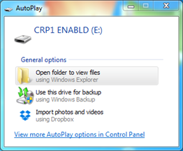](https://wiki.elseta.com/uploads/images/gallery/2021-06/image-1623935180203.png)Fig. 10.1. Reconnecting as a mass storage device Delete the existing file “firmware.bin” and simply upload a new firmware file by dragging and dropping as in Fig. 10.2. [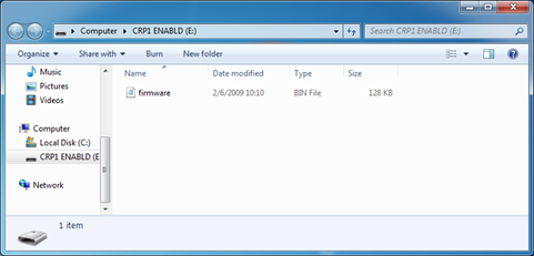](https://wiki.elseta.com/uploads/images/gallery/2021-06/image-1623935213196.png)Fig. 10.2 Mass storage device for firmware upload Reconnect the device and check the firmware version. It should have changed. # Firmware version 2 # IOMod Meter User Manual ### 1. Introduction IOMod Meter is a compact-sized, stand-alone power meter for measuring analog AC input signals from low-power current and voltage sensors. It measures three phases of AC voltage and current amplitudes and phase shifts. Unlike IOMod 4Cs4Vs IOMod Meter only has three inputs for each phase current and voltage measurements. The measured and calculated values are transmitted to the host system via the communication protocol **Modbus RTU, IEC 60870-5-101 or IEC 60870-5-103**. #### 1.1 Features - 3 AC current sensor inputs according to IEC 60044-8 (nominal value 225 mV); - 3 AC voltage sensor inputs according to IEC 60044-7 (nominal value 3.25/√3 V); - 32 samples per cycle; - FFT-based calculation with harmonic information; - Additional measurements of: - Frequency (Nominal frequencies: 50 and 60 Hz; Frequency range: 45–65 Hz); - Active, reactive, and apparent power; - Neutral voltage, neutral current; - Power factor; - Phase angle; - Firmware upgrade over USB, RS485; - Configurable using the IOMOD Utility app for user-friendly setup; - RS-485 interface with a switchable terminating resistor; - Compact case with a removable transparent front panel; - DIN rail mounting for seamless integration into industrial systems; #### 1.2 Block diagram [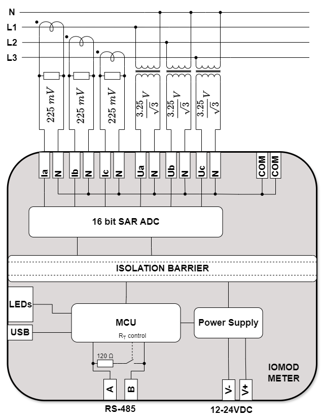](https://wiki.elseta.com/uploads/images/gallery/2025-02/image-1740038444975-drawio.png) Fig. 1.2.1. IOMOD Meter internal structure and block diagram ### 2. Hardware data #### 2.1 Mechanical drawings [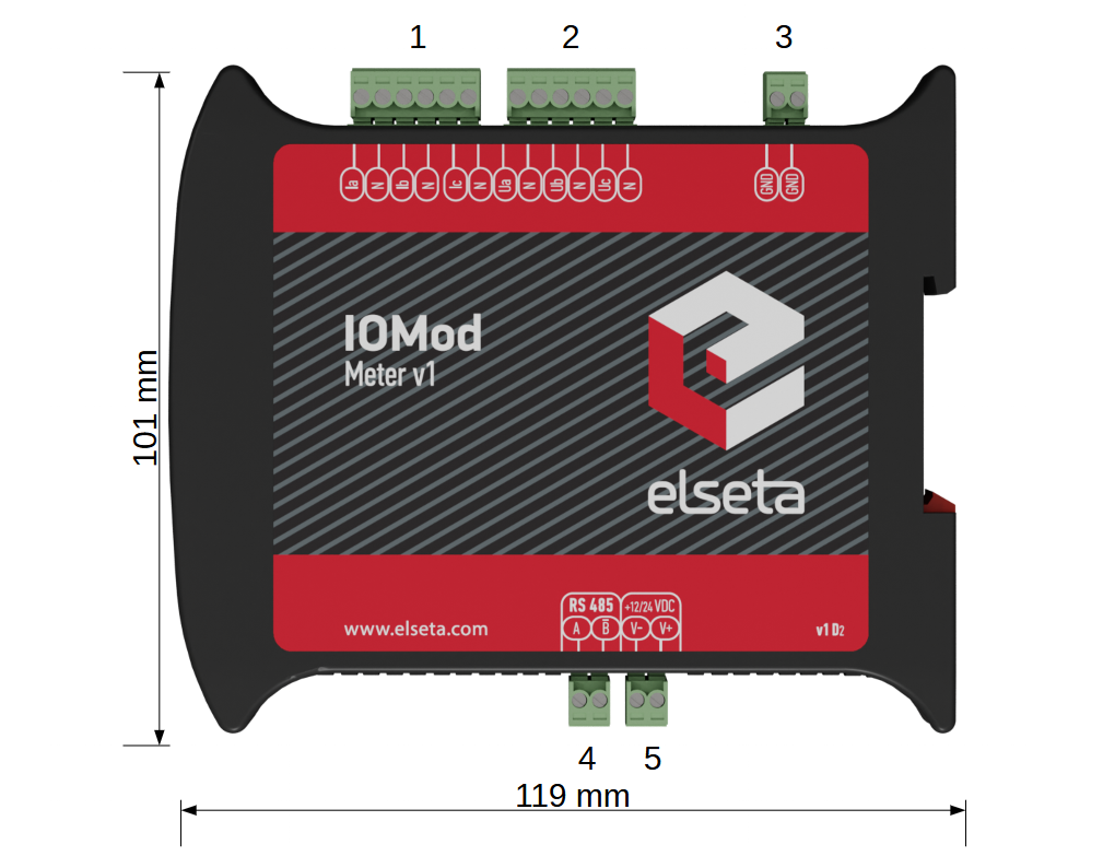](https://wiki.elseta.com/uploads/images/gallery/2025-02/image-1738838645151.png) Fig. 2.1.1. IOMod Meter side view with dimensions and terminal description. 1 – current measurement inputs; 2 – voltage measurement inputs; 3 – ground input for analogue measurements; 4 - RS485 interface; 5 - power supply input [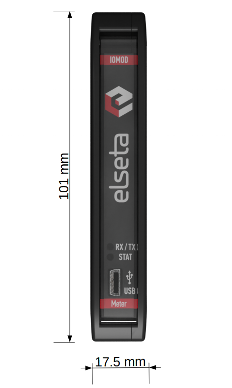](https://wiki.elseta.com/uploads/images/gallery/2025-02/image-1738838959320.png) Fig. 2.1.2 IOMOD Meter front view with measurements #### 2.2 Terminal Connections IOMod Meter has 18 terminals, which are depicted below: [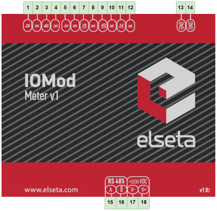](https://wiki.elseta.com/uploads/images/gallery/2025-02/image-1738841460195.png) Fig. 2.2.1 IOMod Meter terminal diagram The description of each terminal can be found in the table below: Table 2.2.1 Terminal Specifications| **Terminal number** | **Terminal name** | **Description** |
| 1 | Ia | Phase current 1 |
| 2 | N | |
| 3 | Ib | Phase current 2 or neutral current in case of I0 metered mode |
| 4 | N | |
| 5 | Ic | Phase current 3 |
| 6 | N | |
| 7 | Ua | Phase voltage 1 or phase current 1 in case of 3I3I connection mode |
| 8 | N | |
| 9 | Ub | Phase voltage 2 or phase current 2 in case of 3I3I connection mode, or neutral current in case of 3I3I connection mode, along with I0 metered mode |
| 10 | N | |
| 11 | Uc | Phase voltage 3 or phase current 3 in case of 3I3I connection mode |
| 12 | N | |
| 13 | COM | Analogue measurements common neutral terminals |
| 14 | COM | |
| 15 | A | RS-485 interface port |
| 16 | B̄ | |
| 17 | V- | Power source inputs |
| 18 | V+ |
| **Name** | **LED color** | **Description** |
| RX/TX | 🟢 (green) | A blinking green light indicates active communication via the RS-485 interface. |
| STAT | 🟢 (green) | The power source is connected to the power supply input. |
| 🔵 (blue) | IOMod Meter is connected to an external device via a USB mini cable. |
| **System** | ||
| Dimension | 101 x 119 x 17.5 mm | |
| Case | ABS, black | |
| Working environment | Indoor | |
| Operating temperature | -40°C ... +85°C | |
| Recommended operating conditions | 5–60°C and 20–80%RH; | |
| Configuration | USB, RS485 | |
| Firmware upgrade | USB, RS485 | |
| **Electrical specifications** | ||
| Inputs | Resolution | 16 bits |
| Input resistance | ~1 MΩ | |
| Input capacitance | < 170 pF | |
| Input ranges | ±10 V (amplitude) | |
| Nominal values | Current input: 225 mV (rms) Voltage input: 1.876 V (rms) | |
| Overvoltage protection for all inputs | up to ±20 V (amplitude) | |
| **Power** | ||
| Power Supply | 9–33 VDC (full range) | |
| Current consumption | 40 mA @ 12 VDC, 20 mA @ 24 VDC | |
| **Parameter** | **Range** | **Default value** |
| Connection mode | 3I3I, 3I3U | 3I3U |
| Frequency | 50 Hz, 60 Hz | 50 Hz |
| Value update time (ms) \* | 20-60000 | 500 |
| Measurands set \*\* | 1-4 | 1 |
| Scale factor \*\* | 1.2, 1.4 | 1.2 |
| **Parameter** | **Range** | **Default value** |
| Primary current (A) | 1–2000 | 100 |
| Primary voltage (kV) | 0.2–60.0 | 10.0 |
| Current sensor (mV) | 100–300 | 225 |
| Voltage sensor (V) | 1.0–3.0 | 1.876 |
| I0 mode | Calculated, Metered | Calculated |
| Primary current I0 | 1–2000 | 100 |
| **Parameter** | **Range** | **Default value** |
| Primary current ch1 (A) | 1–2000 | 100 |
| Primary current ch2 (A) | 1–2000 | 100 |
| Current sensor ch1 (mV) | 100–300 | 225 |
| Current sensor ch2 (mV) | 100–300 | 225 |
| I0 mode ch1 | Calculated, Metered | Calculated |
| I0 mode ch2 | Calculated, Metered | Calculated |
| Primary current I0 ch1 | 1–2000 | 100 |
| Primary current I0 ch2 | 1–2000 | 100 |
| **Address** **(Dec)** | **Description** | **Units** | **Data type** | **Access** |
| 0 | Phase L1 current | % x10 | UINT16 | R |
| 1 | Phase L2 current | % x10 | UINT16 | R |
| 2 | Phase L3 current | % x10 | UINT16 | R |
| 3 | Calculated neutral current | % x10 | UINT16 | R |
| 4 | Calculated line voltage U12 | % x10 | UINT16 | R |
| 5 | Calculated line voltage U23 | % x10 | UINT16 | R |
| 6 | Calculated line voltage U31 | % x10 | UINT16 | R |
| 7 | Calculated zero sequence voltage | % x10 | UINT16 | R |
| 8 | Total 3-phase apparent power (S1+S2+S3) | % x10 | UINT16 | R |
| 9 | Total 3-phase active power (P1+P2+P3) | % x10 | INT16 | R |
| 10 | Total 3-phase reactive power (Q1+Q2+Q3) | % x10 | INT16 | R |
| 11 | Total 3-phase power factor | x1000 | INT16 | R |
| 12 | Total harmonic distortions of U1 voltage | UINT16 | R | |
| 13 | Total harmonic distortions of U2 voltage | UINT16 | R | |
| 14 | Total harmonic distortions of U3 voltage | UINT16 | R | |
| 15 | Total harmonic distortions of I1 current | UINT16 | R | |
| 16 | Total harmonic distortions of I2 current | UINT16 | R | |
| 17 | Total harmonic distortions of I3 current | UINT16 | R | |
| 18 | 3rd harmonic level of the I1 current | % | UINT16 | R |
| 19 | 5th harmonic level of I1 current | % | UINT16 | R |
| 20 | 7th harmonic level of I1 current | % | UINT16 | R |
| 21 | 9th harmonic level of I1 current | % | UINT16 | R |
| 22 | 3rd harmonic level of the I2 current | % | UINT16 | R |
| 23 | 5th harmonic level of I2 current | % | UINT16 | R |
| 24 | 7th harmonic level of I2 current | % | UINT16 | R |
| 25 | 9th harmonic level of I2 current | % | UINT16 | R |
| 26 | 3rd harmonic level of the I3 current | % | UINT16 | R |
| 27 | 5th harmonic level of I3 current | % | UINT16 | R |
| 28 | 7th harmonic level of I3 current | % | UINT16 | R |
| 29 | 9th harmonic level of I3 current | % | UINT16 | R |
| 30 | 3rd harmonic level of U1 voltage | % | UINT16 | R |
| 31 | 5th harmonic level of U1 voltage | % | UINT16 | R |
| 32 | 7th harmonic level of U1 voltage | % | UINT16 | R |
| 33 | 9th harmonic level of U1 voltage | % | UINT16 | R |
| 34 | 3rd harmonic level of U2 voltage | % | UINT16 | R |
| 35 | 5th harmonic level of U2 voltage | % | UINT16 | R |
| 36 | 7th harmonic level of U2 voltage | % | UINT16 | R |
| 37 | 9th harmonic level of U2 voltage | % | UINT16 | R |
| 38 | 3rd harmonic level of U3 voltage | % | UINT16 | R |
| 39 | 5th harmonic level of U3 voltage | % | UINT16 | R |
| 40 | 7th harmonic level of U3 voltage | % | UINT16 | R |
| 41 | 9th harmonic level of U3 voltage | % | UINT16 | R |
| 42 | Phase L1 active power | % x10 | INT16 | R |
| 43 | Phase L2 active power | % x10 | INT16 | R |
| 44 | Phase L3 active power | % x10 | INT16 | R |
| 45 | Phase L1 reactive power | % x10 | INT16 | R |
| 46 | Phase L2 reactive power | % x10 | INT16 | R |
| 47 | Phase L3 reactive power | % x10 | INT16 | R |
| 48 | The phase angle of U1 voltage | 0.1 deg | INT16 | R |
| 49 | The phase angle of U2 voltage | 0.1 deg | INT16 | R |
| 50 | The phase angle of U3 voltage | 0.1 deg | INT16 | R |
| 51 | Phase L1 voltage | % x10 | UINT16 | R |
| 52 | Phase L2 voltage | % x10 | UINT16 | R |
| 53 | Phase L3 voltage | % x10 | UINT16 | R |
| 54 | Frequency of phase L1 voltage | Hz x100 | UINT16 | R |
| 55 | Input I4 current | % x10 | UINT16 | R |
| 56 | Input U4 voltage | % x10 | UINT16 | R |
| 57 | S1 phase apparent power | % x10 | INT16 | R |
| 58 | S2 phase apparent power | % x10 | INT16 | R |
| 59 | S3 phase apparent power | % x10 | INT16 | R |
| 60 | L1 phase power factor | % x10 | INT16 | R |
| 61 | L2 phase power factor | % x10 | INT16 | R |
| 62 | L3 phase power factor | % x10 | INT16 | R |
| 63 | The angle of the I1 current | 0.1 deg | INT16 | R |
| 64 | The angle of the I2 current | 0.1 deg | INT16 | R |
| 65 | The angle of the I3 current | 0.1 deg | INT16 | R |
| 66 | Line voltage U12 angle | 0.1 deg | INT16 | R |
| 67 | Line voltage U23 angle | 0.1 deg | INT16 | R |
| 68 | Line voltage U31 angle | 0.1 deg | INT16 | R |
| 69 | Current positive sequence | Data \* 10 | UINT16 | % |
| 70 | Current negative sequence | % x10 | UINT16 | R |
| 71 | Voltage positive sequence | % x10 | UINT16 | R |
| 72 | Voltage negative sequence | % x10 | UINT16 | R |
| 73 | Current I0 angle | 0.1 deg | UINT16 | R |
| 74 | Current I4 angle | 0.1 deg | UINT16 | R |
| 75 | Voltage U0 angle | 0.1 deg | UINT16 | R |
| 76 | Voltage U4 angle | 0.1 deg | UINT16 | R |
| 77 | Current Ip angle | 0.1 deg | UINT16 | R |
| 78 | Current In angle | 0.1 deg | UINT16 | R |
| 79 | Current Up angle | 0.1 deg | UINT16 | R |
| 80 | Current Un angle | 0.1 deg | UINT16 | R |
| 81 | Current I1 2nd harmonic | % x10 | UINT16 | R |
| 82 | Current I2 2nd harmonic | % x10 | UINT16 | R |
| 83 | Current I3 2nd harmonic | % x10 | UINT16 | R |
| 84 | Current I1 channel 2 | % x10 | UINT16 | R |
| 85 | Current I2 channel 2 | % x10 | UINT16 | R |
| 86 | Current I3 channel 2 | % x10 | UINT16 | R |
| 87 | Current I0 channel 2 | % x10 | UINT16 | R |
| 88 | Current I4 channel 2 | % x10 | UINT16 | R |
| 89 | Current Ip channel 2 | % x10 | UINT16 | R |
| 90 | Current In channel 2 | % x10 | UINT16 | R |
| 91 | Current I1 channel 2 angle | 0.1 deg | UINT16 | R |
| 92 | Current I2 channel 2 angle | 0.1 deg | UINT16 | R |
| 93 | Current I3 channel 2 angle | 0.1 deg | UINT16 | R |
| 94 | Current I0 channel 2 angle | 0.1 deg | UINT16 | R |
| 95 | Current I4 channel 2 angle | 0.1 deg | UINT16 | R |
| 96 | Current Ip channel 2 angle | 0.1 deg | UINT16 | R |
| 97 | Current In channel 2 angle | 0.1 deg | UINT16 | R |
| 98 | Current I1 2nd harmonic channel 2 | 0.1 deg | UINT16 | R |
| 99 | Current I2 2nd harmonic channel 2 | 0.1 deg | UINT16 | R |
| 100 | Current I3 2nd harmonic channel 2 | 0.1 deg | UINT16 | R |
| 101 | THD of current I1 channel 2 | UINT16 | R | |
| 102 | THD of current I2 channel 2 | UINT16 | R | |
| 103 | THD of current I3 channel 2 | UINT16 | R | |
| 104 | Current I1 3rd harmonic channel 2 | % | UINT16 | R |
| 105 | Current I1 5th harmonic channel 2 | % | UINT16 | R |
| 106 | Current I1 7th harmonic channel 2 | % | UINT16 | R |
| 107 | Current I1 9th harmonic channel 2 | % | UINT16 | R |
| 108 | Current I2 3rd harmonic channel 2 | % | UINT16 | R |
| 109 | Current I2 5th harmonic channel 2 | % | UINT16 | R |
| 110 | Current I2 7th hamonic channel 2 | % | UINT16 | R |
| 111 | Current I2 9th harmonic channel 2 | % | UINT16 | R |
| 112 | Current I3 3rd harmonic channel 2 | % | UINT16 | R |
| 113 | Current I3 5th harmonic channel 2 | % | UINT16 | R |
| 114 | Current I3 7th harmonic channel 2 | % | UINT16 | R |
| 115 | Current I3 9th harmonic channel 2 | % | UINT16 | R |
| 116-117 | Active import energy | kWh | UINT32 | R |
| 118-119 | Active export energy | kWh | UINT32 | R |
| 120-121 | Reactive import energy | kVArh | UINT32 | R |
| 122-123 | Reactive export energy | kVArh | UINT32 | R |
| **Address (Dec)** | **Description** | **Units** | **Data type** | **Access** |
| 200 - 201 | Current I1 | A | FLOAT | R |
| 202 - 203 | Current I2 | A | FLOAT | R |
| 204 - 205 | Current I3 | A | FLOAT | R |
| 206 - 207 | Current I0 | A | FLOAT | R |
| 208 - 209 | Voltage U12 | U | FLOAT | R |
| 210 - 211 | Voltage U23 | U | FLOAT | R |
| 212 - 213 | Voltage U31 | U | FLOAT | R |
| 214 - 215 | Voltage U1 | U | FLOAT | R |
| 216 - 217 | Voltage U2 | U | FLOAT | R |
| 218 - 219 | Voltage U3 | U | FLOAT | R |
| 220 - 221 | Voltage U0 | U | FLOAT | R |
| 222 - 223 | Voltage U1 angle | ° | FLOAT | R |
| 224 - 225 | Voltage U2 angle | ° | FLOAT | R |
| 226 - 227 | Voltage U3 angle | ° | FLOAT | R |
| 228 - 229 | Apparent power Σ3 phase | VA | FLOAT | R |
| 230 - 231 | Active power Σ3 phase | W | FLOAT | R |
| 232 - 233 | Reactive power Σ3 phase | Var | FLOAT | R |
| 234 - 235 | Power factor Σ3 phase | FLOAT | R | |
| 236 - 237 | Apparent power S1 | VA | FLOAT | R |
| 238 - 239 | Apparent power S2 | VA | FLOAT | R |
| 240 - 241 | Apparent power S3 | VA | FLOAT | R |
| 242 - 243 | Active power P1 | W | FLOAT | R |
| 244 - 245 | Active power P2 | W | FLOAT | R |
| 246 - 247 | Active power P3 | W | FLOAT | R |
| 248 - 249 | Reactive power Q1 | Var | FLOAT | R |
| 250 - 251 | Reactive power Q2 | Var | FLOAT | R |
| 252 - 253 | Reactive power Q3 | Var | FLOAT | R |
| 254 - 255 | Power factor PF1 | FLOAT | R | |
| 256 - 257 | Power factor PF2 | FLOAT | R | |
| 258 - 259 | Power factor PF3 | FLOAT | R | |
| 260 - 261 | Frequency | Hz | FLOAT | R |
| 262 - 263 | THD Voltage U1 | FLOAT | R | |
| 264 - 265 | THD Voltage U2 | FLOAT | R | |
| 266 - 267 | THD Voltage U3 | FLOAT | R | |
| 268 - 269 | THD Current I1 | FLOAT | R | |
| 270 - 271 | THD Current I2 | FLOAT | R | |
| 272 - 273 | THD Current I3 | FLOAT | R | |
| 274 - 275 | Current I1 3rd harmonic | FLOAT | R | |
| 276 - 277 | Current I1 5th harmonic | FLOAT | R | |
| 278 - 279 | Current I1 7th harmonic | FLOAT | R | |
| 280 - 281 | Current I1 9th harmonic | FLOAT | R | |
| 282 - 283 | Current I2 3rd harmonic | FLOAT | R | |
| 284 - 285 | Current I2 5th harmonic | FLOAT | R | |
| 286 - 287 | Current I2 7th harmonic | FLOAT | R | |
| 288 - 289 | Current I2 9th harmonic | FLOAT | R | |
| 290 - 291 | Current I3 3rd harmonic | FLOAT | R | |
| 292 - 293 | Current I3 5th harmonic | FLOAT | R | |
| 294 - 295 | Current I3 7th harmonic | FLOAT | R | |
| 296 - 297 | Current I3 9th harmonic | FLOAT | R | |
| 298 - 299 | Voltage U1 3rd harmonic | FLOAT | R | |
| 300 - 301 | Voltage U1 5th harmonic | FLOAT | R | |
| 302 - 303 | Voltage U1 7th harmonic | FLOAT | R | |
| 304 - 305 | Voltage U1 9th harmonic | FLOAT | R | |
| 306 - 307 | Voltage U2 3rd harmonic | FLOAT | R | |
| 308 - 309 | Voltage U2 5th harmonic | FLOAT | R | |
| 310 - 311 | Voltage U2 7th harmonic | FLOAT | R | |
| 312 - 313 | Voltage U2 9th harmonic | FLOAT | R | |
| 314 - 315 | Voltage U3 3rd harmonic | FLOAT | R | |
| 316 - 317 | Voltage U3 5th harmonic | FLOAT | R | |
| 318 - 319 | Voltage U3 7th harmonic | FLOAT | R | |
| 320 - 321 | Voltage U3 9th harmonic | FLOAT | R | |
| 322 - 323 | Current I4 | A | FLOAT | R |
| 324 - 325 | Voltage U4 | U | FLOAT | R |
| 326 - 327 | Current I1 angle | ° | FLOAT | R |
| 328 - 329 | Current I2 angle | ° | FLOAT | R |
| 330 - 331 | Current I3 angle | ° | FLOAT | R |
| 332 - 333 | Current I0 angle | ° | FLOAT | R |
| 334 - 335 | Voltage U0 angle | ° | FLOAT | R |
| 336 - 337 | Voltage U12 angle | ° | FLOAT | R |
| 338 - 339 | Voltage U23 angle | ° | FLOAT | R |
| 340 - 341 | Voltage U31 angle | ° | FLOAT | R |
| 342 - 343 | Current I4 angle | ° | FLOAT | R |
| 344 - 345 | Voltage U4 angle | ° | FLOAT | R |
| 346 - 347 | Current positive seq Ip | A | FLOAT | R |
| 348 - 349 | Current negative seq In | A | FLOAT | R |
| 350 - 351 | Current Ip angle | ° | FLOAT | R |
| 352 - 353 | Current In angle | ° | FLOAT | R |
| 354 - 355 | Voltage positive seq Up | U | FLOAT | R |
| 356 - 357 | Voltage negative seq Un | U | FLOAT | R |
| 358 - 359 | Voltage Up angle | ° | FLOAT | R |
| 360 - 361 | Voltage Un angle | ° | FLOAT | R |
| 362 - 363 | Current I1 2nd harmonic | FLOAT | R | |
| 364 - 365 | Current I2 2nd harmonic | FLOAT | R | |
| 366 - 367 | Current I3 2nd harmonic | FLOAT | R | |
| 368 - 369 | Current I1 channel 2 | A | FLOAT | R |
| 370 - 371 | Current I2 channel 2 | A | FLOAT | R |
| 372 - 373 | Current I3 channel 2 | A | FLOAT | R |
| 374 - 375 | Current I0 channel 2 | A | FLOAT | R |
| 376 - 377 | Current I4 channel 2 | A | FLOAT | R |
| 378 - 379 | Current I1 channel 2 angle | ° | FLOAT | R |
| 380 - 381 | Current I2 channel 2 angle | ° | FLOAT | R |
| 382 - 383 | Current I3 channel 2 angle | ° | FLOAT | R |
| 384 - 385 | Current I0 channel 2 angle | ° | FLOAT | R |
| 386 - 387 | Current I4 channel 2 angle | ° | FLOAT | R |
| 388 - 389 | Current Ip channel 2 | A | FLOAT | R |
| 390 - 391 | Current In channel 2 | A | FLOAT | R |
| 392 - 393 | Current Ip channel 2 angle | ° | FLOAT | R |
| 394 - 395 | Current In channel 2 angle | ° | FLOAT | R |
| 396 - 397 | Current I1 2nd harmonic ch2 | FLOAT | R | |
| 398 - 399 | Current I2 2nd harmonic ch2 | FLOAT | R | |
| 400 - 401 | Current I3 2nd harmonic ch2 | FLOAT | R | |
| 402 - 403 | THD Current I1 ch2 | FLOAT | R | |
| 404 - 405 | THD Current I2 ch2 | FLOAT | R | |
| 406 - 407 | THD Current I3 ch2 | FLOAT | R | |
| 408 - 409 | Current I1 3rd harmonic ch2 | FLOAT | R | |
| 410 - 411 | Current I1 5th harmonic ch2 | FLOAT | R | |
| 412 - 413 | Current I1 7th harmonic ch2 | FLOAT | R | |
| 414 - 415 | Current I1 9th harmonic ch2 | FLOAT | R | |
| 416 - 417 | Current I2 3rd harmonic ch2 | FLOAT | R | |
| 418 - 419 | Current I2 5th harmonic ch2 | FLOAT | R | |
| 420 - 421 | Current I2 7th harmonic ch2 | FLOAT | R | |
| 422 - 423 | Current I2 9th harmonic ch2 | FLOAT | R | |
| 424 - 425 | Current I3 3rd harmonic ch2 | FLOAT | R | |
| 426 - 427 | Current I3 5th harmonic ch2 | FLOAT | R | |
| 428 - 429 | Current I3 7th harmonic ch2 | FLOAT | R | |
| 430 - 431 | Current I3 9th harmonic ch2 | FLOAT | R |
| **IOA** | **Description** | **Units** | **TI** |
| 0 | Current I1 | A | 13 (M\_ME\_NC\_1) |
| 1 | Current I2 | A | 13 (M\_ME\_NC\_1) |
| 2 | Current I3 | A | 13 (M\_ME\_NC\_1) |
| 3 | Current I0 | A | 13 (M\_ME\_NC\_1) |
| 4 | Voltage U12 | U | 13 (M\_ME\_NC\_1) |
| 5 | Voltage U23 | U | 13 (M\_ME\_NC\_1) |
| 6 | Voltage U31 | U | 13 (M\_ME\_NC\_1) |
| 7 | Voltage U1 | U | 13 (M\_ME\_NC\_1) |
| 8 | Voltage U2 | U | 13 (M\_ME\_NC\_1) |
| 9 | Voltage U3 | U | 13 (M\_ME\_NC\_1) |
| 10 | Voltage U0 | U | 13 (M\_ME\_NC\_1) |
| 11 | Voltage U1 angle | ° | 13 (M\_ME\_NC\_1) |
| 12 | Voltage U2 angle | ° | 13 (M\_ME\_NC\_1) |
| 13 | Voltage U3 angle | ° | 13 (M\_ME\_NC\_1) |
| 14 | Apparent power Σ 3-phase | VA | 13 (M\_ME\_NC\_1) |
| 15 | Active power Σ 3-phase | W | 13 (M\_ME\_NC\_1) |
| 16 | Reactive power Σ 3-phase | Var | 13 (M\_ME\_NC\_1) |
| 17 | Power factor Σ 3-phase | 13 (M\_ME\_NC\_1) | |
| 18 | Apparent power S1 | VA | 13 (M\_ME\_NC\_1) |
| 19 | Apparent power S2 | VA | 13 (M\_ME\_NC\_1) |
| 20 | Apparent power S3 | VA | 13 (M\_ME\_NC\_1) |
| 21 | Active power P1 | W | 13 (M\_ME\_NC\_1) |
| 22 | Active power P2 | W | 13 (M\_ME\_NC\_1) |
| 23 | Active power P3 | W | 13 (M\_ME\_NC\_1) |
| 24 | Reactive power Q1 | Var | 13 (M\_ME\_NC\_1) |
| 25 | Reactive power Q2 | Var | 13 (M\_ME\_NC\_1) |
| 26 | Reactive power Q3 | Var | 13 (M\_ME\_NC\_1) |
| 27 | Power factor PF1 | 13 (M\_ME\_NC\_1) | |
| 28 | Power factor PF2 | 13 (M\_ME\_NC\_1) | |
| 29 | Power factor PF3 | 13 (M\_ME\_NC\_1) | |
| 30 | Frequency | Hz | 13 (M\_ME\_NC\_1) |
| 31 | THD Voltage U1 | 13 (M\_ME\_NC\_1) | |
| 32 | THD Voltage U2 | 13 (M\_ME\_NC\_1) | |
| 33 | THD Voltage U3 | 13 (M\_ME\_NC\_1) | |
| 34 | THD Current I1 | 13 (M\_ME\_NC\_1) | |
| 35 | THD Current I2 | 13 (M\_ME\_NC\_1) | |
| 36 | THD Current I3 | 13 (M\_ME\_NC\_1) | |
| 37 | Current I1 3rd harmonic | 13 (M\_ME\_NC\_1) | |
| 38 | Current I1 5th harmonic | 13 (M\_ME\_NC\_1) | |
| 39 | Current I1 7th harmonic | 13 (M\_ME\_NC\_1) | |
| 40 | Current I1 9th harmonic | 13 (M\_ME\_NC\_1) | |
| 41 | Current I2 3rd harmonic | 13 (M\_ME\_NC\_1) | |
| 42 | Current I2 5th harmonic | 13 (M\_ME\_NC\_1) | |
| 43 | Current I2 7th harmonic | 13 (M\_ME\_NC\_1) | |
| 44 | Current I2 9th harmonic | 13 (M\_ME\_NC\_1) | |
| 45 | Current I3 3rd harmonic | 13 (M\_ME\_NC\_1) | |
| 46 | Current I3 5th harmonic | 13 (M\_ME\_NC\_1) | |
| 47 | Current I3 7th harmonic | 13 (M\_ME\_NC\_1) | |
| 48 | Current I3 9th harmonic | 13 (M\_ME\_NC\_1) | |
| 49 | Voltage U1 3rd harmonic | 13 (M\_ME\_NC\_1) | |
| 50 | Voltage U1 5th harmonic | 13 (M\_ME\_NC\_1) | |
| 51 | Voltage U1 7th harmonic | 13 (M\_ME\_NC\_1) | |
| 52 | Voltage U1 9th harmonic | 13 (M\_ME\_NC\_1) | |
| 53 | Voltage U2 3rd harmonic | 13 (M\_ME\_NC\_1) | |
| 54 | Voltage U2 5th harmonic | 13 (M\_ME\_NC\_1) | |
| 55 | Voltage U2 7th harmonic | 13 (M\_ME\_NC\_1) | |
| 56 | Voltage U2 9th harmonic | 13 (M\_ME\_NC\_1) | |
| 57 | Voltage U3 3rd harmonic | 13 (M\_ME\_NC\_1) | |
| 58 | Voltage U3 5th harmonic | 13 (M\_ME\_NC\_1) | |
| 59 | Voltage U3 7th harmonic | 13 (M\_ME\_NC\_1) | |
| 60 | Voltage U3 9th harmonic | 13 (M\_ME\_NC\_1) | |
| 61 | Current I4 | A | 13 (M\_ME\_NC\_1) |
| 62 | Voltage U4 | U | 13 (M\_ME\_NC\_1) |
| 63 | Current I1 angle | ° | 13 (M\_ME\_NC\_1) |
| 64 | Current I2 angle | ° | 13 (M\_ME\_NC\_1) |
| 65 | Current I3 angle | ° | 13 (M\_ME\_NC\_1) |
| 66 | Current I0 angle | ° | 13 (M\_ME\_NC\_1) |
| 67 | Voltage U0 angle | ° | 13 (M\_ME\_NC\_1) |
| 68 | Voltage U12 angle | ° | 13 (M\_ME\_NC\_1) |
| 69 | Voltage U23 angle | ° | 13 (M\_ME\_NC\_1) |
| 70 | Voltage U31 angle | ° | 13 (M\_ME\_NC\_1) |
| 71 | Current I4 angle | ° | 13 (M\_ME\_NC\_1) |
| 72 | Voltage U4 angle | ° | 13 (M\_ME\_NC\_1) |
| 73 | Current positive seq Ip | A | 13 (M\_ME\_NC\_1) |
| 74 | Current negative seq In | A | 13 (M\_ME\_NC\_1) |
| 75 | Current Ip angle | ° | 13 (M\_ME\_NC\_1) |
| 76 | Current In angle | ° | 13 (M\_ME\_NC\_1) |
| 77 | Voltage positive seq Up | U | 13 (M\_ME\_NC\_1) |
| 78 | Voltage negative seq Un | U | 13 (M\_ME\_NC\_1) |
| 79 | Voltage Up angle | ° | 13 (M\_ME\_NC\_1) |
| 80 | Voltage Un angle | ° | 13 (M\_ME\_NC\_1) |
| 81 | Current I1 2nd harmonic | 13 (M\_ME\_NC\_1) | |
| 82 | Current I2 2nd harmonic | 13 (M\_ME\_NC\_1) | |
| 83 | Current I3 2nd harmonic | 13 (M\_ME\_NC\_1) | |
| 84 | Current I1 channel 2 | A | 13 (M\_ME\_NC\_1) |
| 85 | Current I2 channel 2 | A | 13 (M\_ME\_NC\_1) |
| 86 | Current I3 channel 2 | A | 13 (M\_ME\_NC\_1) |
| 87 | Current I0 channel 2 | A | 13 (M\_ME\_NC\_1) |
| 88 | Current I4 channel 2 | A | 13 (M\_ME\_NC\_1) |
| 89 | Current I1 channel 2 angle | ° | 13 (M\_ME\_NC\_1) |
| 90 | Current I2 channel 2 angle | ° | 13 (M\_ME\_NC\_1) |
| 91 | Current I3 channel 2 angle | ° | 13 (M\_ME\_NC\_1) |
| 92 | Current I0 channel 2 angle | ° | 13 (M\_ME\_NC\_1) |
| 93 | Current I4 channel 2 angle | ° | 13 (M\_ME\_NC\_1) |
| 94 | Current Ip channel 2 | A | 13 (M\_ME\_NC\_1) |
| 95 | Current In channel 2 | A | 13 (M\_ME\_NC\_1) |
| 96 | Current Ip channel 2 angle | ° | 13 (M\_ME\_NC\_1) |
| 97 | Current In channel 2 angle | ° | 13 (M\_ME\_NC\_1) |
| 98 | Current I1 2nd harmonic ch2 | 13 (M\_ME\_NC\_1) | |
| 99 | Current I2 2nd harmonic ch2 | 13 (M\_ME\_NC\_1) | |
| 100 | Current I3 2nd harmonic ch2 | 13 (M\_ME\_NC\_1) | |
| 101 | THD Current I1 ch2 | 13 (M\_ME\_NC\_1) | |
| 102 | THD Current I2 ch2 | 13 (M\_ME\_NC\_1) | |
| 103 | THD Current I3 ch2 | 13 (M\_ME\_NC\_1) | |
| 104 | Current I1 3rd harmonic ch2 | 13 (M\_ME\_NC\_1) | |
| 105 | Current I1 5th harmonic ch2 | 13 (M\_ME\_NC\_1) | |
| 106 | Current I1 7th harmonic ch2 | 13 (M\_ME\_NC\_1) | |
| 107 | Current I1 9th harmonic ch2 | 13 (M\_ME\_NC\_1) | |
| 108 | Current I2 3rd harmonic ch2 | 13 (M\_ME\_NC\_1) | |
| 109 | Current I2 5th harmonic ch2 | 13 (M\_ME\_NC\_1) | |
| 110 | Current I2 7th harmonic ch2 | 13 (M\_ME\_NC\_1) | |
| 111 | Current I2 9th harmonic ch2 | 13 (M\_ME\_NC\_1) | |
| 112 | Current I3 3rd harmonic ch2 | 13 (M\_ME\_NC\_1) | |
| 113 | Current I3 5th harmonic ch2 | 13 (M\_ME\_NC\_1) | |
| 114 | Current I3 7th harmonic ch2 | 13 (M\_ME\_NC\_1) | |
| 115 | Current I3 9th harmonic ch2 | 13 (M\_ME\_NC\_1) | |
| 400 | Active import energy | kWh | 7 (M\_BO\_NA\_1) |
| 401 | Active export energy | kWh | 7 (M\_BO\_NA\_1) |
| 402 | Reactive import energy | kVArh | 7 (M\_BO\_NA\_1) |
| 403 | Reactive export energy | kVArh | 7 (M\_BO\_NA\_1) |
| **Set Nr.** | **TYPE** | **FUN\*** | **INF** | **Qty of data** | **Information elements (measurands)** |
| 1 | 9 | 253 | 148 | 9 | I1, I2, I3, U1, U2, U3, P, Q, f |
| 2 | 9 | 253 | 149 | 23 | I1, I2, I3, I4, U1, U2, U3, U4, P1, P2, P3, Q1, Q2, Q3, S1, S2, S3, PF1, PF2, PF3, U12(angle), U23(angle), U13(angle) |
| 3 | 9 | 253 | 150 | 60 | I1, I2, I3, IN, U1, U2, U3, UN, P1, P2, P3, Q1, Q2, Q3, S1, S2, S3, PF1, PF2, PF3, U12, U23, U13, f, THDU1, THDU2, THDU3, THDI1, THDI2, THDI3, I1(h2), I1(h3), I1(h5), I1(h7), I1(h9), I2(h2), I2(h3), I2(h5), I2(h7), I2(h9), I3(h2), I3(h3), I3(h5), I3(h7), I3(h9), U1(h2), U1(h3), U1(h5), U1(h7), U1(h9), U2(h2), U2(h3), U2(h5), U2(h7), U2(h9), U3(h2), U3(h3), U3(h5), U3(h7), U3(h9) |
| 4 | 9 | 253 | 151 | 54 | I1, I2, I3, IN, U12, U23, U13, UN, S, P, Q, PF, THDU1, THDU2, THDU3, THDI1, THDI2, THDI3, I1(h3), I1(h5), I1(h7), I1(h9), I2(h3), I2(h5), I2(h7), I2(h9), I3(h3), I3(h5), I3(h7), I3(h9), U1(h3), U1(h5), U1(h7), U1(h9), U2(h3), U2(h5), U2(h7), U2(h9), U3(h3), U3(h5), U3(h7), U3(h9), P1, P2, P3, Q1, Q2, Q3, U1(angle), U2(angle), U3(angle), U1, U2, U3 |
| **Set Nr.** | **TYPE** | **FUN\*** | **INF** | **Qty of data** | **Information elements (measurands)** |
| 1 | 9 | 253 | 148 | 7 | I1(ch1), I2(ch1), I3(ch1), I1(ch2), I2(ch2), I3(ch2), f |
| 2 | 9 | 253 | 149 | 8 | I1(ch1), I2(ch1), I3(ch1), I4(ch1), I1(ch2), I2(ch2), I3(ch2), I4(ch2) |
| 3 | 9 | 253 | 150 | 45 | I1(ch1), I2(ch1), I3(ch1), I0(ch1), I1(ch2), I2(ch2), I3(ch2), I0(ch2), f, THDI1(ch1), THDI2(ch1), THDI3(ch1), I1(h3, ch1), I1(h5, ch1), I1(h7, ch1), I1(h9, ch1), I2(h3, ch1), I2(h5, ch1), I2(h7, ch1), I2(h9, ch1), I3(h3, ch1), I3(h5, ch1), I3(h7, ch1), I3(h9, ch1), THDI1(ch2), THDI2(ch2), THDI3(ch2), I1(h3, ch2), I1(h5, ch2), I1(h7, ch2), I1(h9, ch2), I2(h3, ch2), I2(h5, ch2), I2(h7, ch2), I2(h9, ch2), I3(h3, ch2), I3(h5, ch2), I3(h7, ch2), I3(h9, ch2) |