IOMOD HT
IOMod HT – temperature and humidity sensor
- IOMOD HT User Manual Modbus
- IOMOD HT User Manual IEC 60870-5-103
- IOMOD HT User Manual IEC 60870-5-101
IOMOD HT User Manual Modbus
Introduction
IOMOD HT is used for temperature and humidity data monitoring over Modbus (RTU), IEC 60870-5-103 or IEC 60870-5-101. The advanced version of the device is also capable of switching relays automatically (thermostat function) as configured.
Features
- Temperature measurement in 0.1°C resolution
- Humidity measurement in 0.1% resolution
- Modbus, IEC-60870-5-103 and IEC-60870-5-101 communication over RS485
- 2 normally open relay outputs (advanced version)
- Automatically configurable relay switching on temperature or humidity change
- Configuration over USB console
- Drag and Drop firmware upgrade over USB mass storage
- LED indication for input/output and data transmission
- Spring contact connectors
- Easy connection with WCC Lite gateway and CloudIndustries.eu platform
Operational Information
IOMOD uses Modbus (RTU) or IEC-60870-103 or IEC-60870-101 protocols over RS485 connection, which can be used with cable length up to 1500 meters and connect up to 30 devices on one line. Default Modbus settings are: 9600 baudrate, 8 databits, N parity, 1 stopbit , Slave address - 1.
To read temperature and humidity, user can use device with default settings without configuring it. To read humidity, send 04 Modbus command (Read Input Registers) with resolution of first register (0). Returned value will be measured in % and will be multiplied by 10, to show one decimal place. To read temperature, send 04 (Read Input Registers) with resolution of second register (1). The returned value will be measured in °C and will be multiplied by 10.
PWR LED
Green - Normal operation, device is powered correctly.
RX/TX LED
The RX/TX LED on the IOMod flashes when data is either being transmitted or received via the RS485 port.
IOMod HT advanced temperature and humidity limit operation logic
First Relay (Heater):
- Activation Conditions: When temperature drops below lower limit OR humidity exceeds upper limit.
- Deactivation Conditions: When temperature rises by 5 degrees above the set temperature limit.
This logic ensures that the heater is activated when the conditions are too cold (temperature drops below the lower limit) or too humid, and it's deactivated when the temperature rises sufficiently.
Second Relay (Fan):
- Activation Conditions: When temperature or humidity exceeds the upper limit.
- Deactivation Conditions: When humidity decreases by 10% AND temperature gets below the set temperature limit by 5 degrees.
This logic ensures that the fan is activated when conditions are too hot or humid, and it's deactivated when both humidity decreases sufficiently and temperature decreases to a set level.
To enable thermostat function, user can configure device over USB or over MODBUS. Configurable options are shown in table below.
| CONFIGURABLE OPTIONS | OVER USB | OVER MODBUS |
| Slave Address | Yes | No |
| Baudrate | Yes | No |
| Data, Stop and Parity bits | Yes | No |
| RS485 Terminating Resistor | Yes | No |
| 1st Relay enabled/disabled | Yes | Yes |
| 1st Relay set temperature and humidity limit | Yes | Yes |
| 2nd Relay enabled/disabled | Yes | Yes |
| 2nd Relay set temperature and humidity limit | Yes | Yes |
| Default Settings | Yes | No |
Supported MODBUS functions
IOMod HT basic
04 (0x04) Read Input Registers
Reads current Humidity and Temperature status. Address 0 – Humidity, Address 1 – Temperature; Value is multiplied by 10 to show one decimal place. For example: 23.3 °C will be shown as 233; 50.0 % will be shown as 500 in the Registers.
IOMod HT Advanced
01 (0x01) Read Coils Status
Reads the status of relays (True - closed or False - open). IOMOD HT advanced has 2 relays on coils #6 (heater) and #7 (fan).
03 (0x03) Read Holding Registers
Reads current configuration of relays. Address 2 – Relay #1 (heater) control: 0- disabled; 1 - enabled; Address 3 – Relay #1 (heater) temperature lower limit value; Address 4 - Relay #1 (heater) humidity upper limit value; Address 5 – Relay #2 (fan) control: 0- disabled; 1 - enabled; Address 6 – Relay #2 (fan) temperature upper limit value; Address 7 – Relay #2 (fan) humidity upper limit value;
04 (0x04) Read Input Registers
Reads current Humidity and Temperature status. Address 0 – Humidity, Address 1 – Temperature; Value is multiplied by 10 to show one decimal place. For example: 23.3 °C will be shown as 233; 50.0 % will be shown as 500 in the Registers.
06 (0x06) Preset Single Register
Sets single relay configuration. Address 2 – Sets Relay #1 (heater) On or Off: 0- disabled; 1 - enabled; Address 3 – set Relay #1 (heater) temperature lower limit; valid range -10 to 60; Address 4 - set Relay #1 (heater) humidity upper limit: valid range 0-100; Address 5 – Set Relay #2 (fan) On or Off: 0- disabled; 1 - enabled; Address 6 – set Relay #2 (fan) temperature upper limit; valid range -10 to 60; Address 7 – set Relay #2 (fan) humidity upper limit; valid range 0-100.
Technical information
| System | ||
| Dimensions | 26 (H) x 71 (W) x 71 (L), mm | |
| Case | ABS, white | |
| Working environment | Indoors | |
| Working temperature | -20 ÷ +70 °C | |
| Recommended operating conditions |
5 – 60 °C and 20 – 80 %RH; | |
| Configuration | USB | |
| Firmware upgrade | USB – mass storage device | |
| Electrical Characteristics | Basic | Advanced |
| Termination Resistor | Selectable 120 Ω | Selectable 120 Ω |
| Power supply | 12-24 VDC, 8 mA (nominal); 5-33 VDC (full range) | 24 VDC, 25 mA (nominal); 18-27 VDC (full range) |
| Relays | - | 2 (Normally Open); |
| Relay specifications | Basic | Advanced |
| Resistive load (cosφ=1) | - | 5 A at 250 VAC, 5 A at 30 VDC |
| Inductive load (cosφ=0.4, L/R=7ms) | - | 2 A at 250 VAC, 2 A at 30 VDC |
| Max. switching power | - | 1,250 VA, 150 W |
Device Connection
IOMOD HT has an integrated 120 Ω termination resistor which can be enabled or disabled over USB configuration. It is recommended to use termination at each end of the RS485 cable. See the typical connection diagram on Fig. 1.
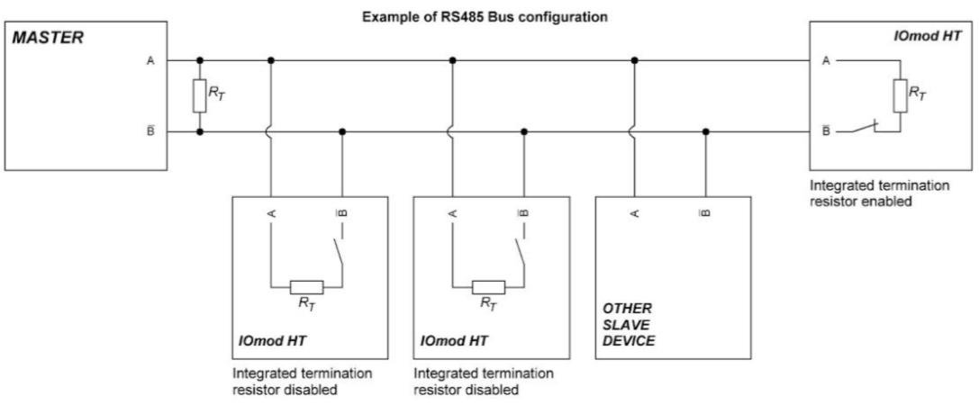
Fig. 1.
Figure 2 shows explanation on device connection.
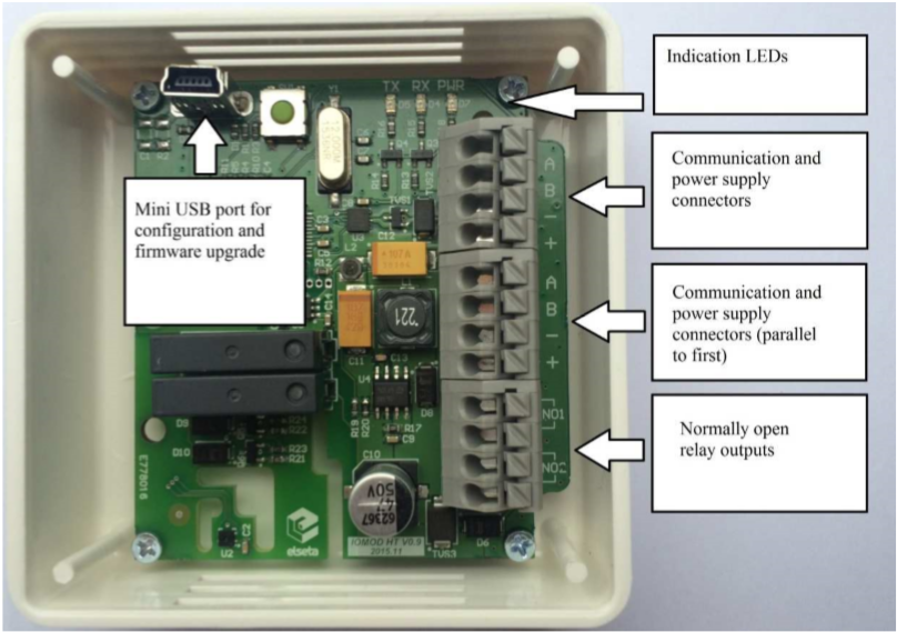 Fig. 2.
Configuration over USB
Driver installation
Device requires USB drivers to work as a Virtual COM port. First-time connection between device and computer could result in “Device driver software was not successfully installed” error such as one shown in Fig. 3.
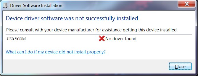
Fig. 3.
A user then should manually install drivers by selecting a downloaded driver folder:
- Go to Control Panel -> Device Manager;
- Select a failing device;
- Press “Update driver software”; screen as in Fig. 4 should appear:
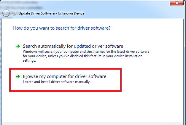
Fig. 4.
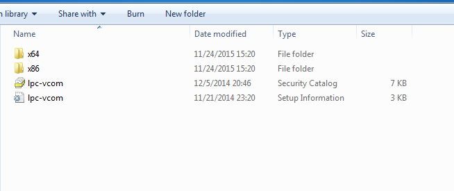
- Select “x86” driver for a 32-bit machine or x64 for a 64-bit machine. If not sure, select a root
folder (folder in which x64 and x86 lay inside, as in Fig. 5).
IOMod HT configuration via PuTTY terminal
Configuration of IOMOD device is done through CLI (Command Line Interface) on virtual COM port. Drivers needed for MS Windows to install VCOM will be provided. To open up CLI simply connect to specific VCOM port with terminal software (it is advised to use PuTTY terminal software. If other software is being used, user might need to send <return> symbol after each command). When connected user should immediately see main screen similar to one in Fig. 6.
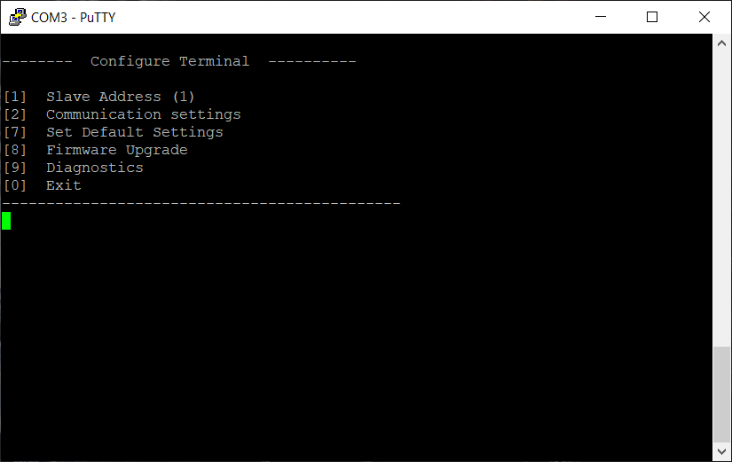 Fig. 6.
If terminal window is accidentally closed without exiting, user can connect to terminal again, and press any key on keyboard to show up main menu once again.
Configuration of device is not possible when USB Simulation Mode is entered. To access configuration menu again user should reset device and then try again.
|
Menu Name |
Function |
Values |
Default Values |
|
| 1. |
Slave Address |
Modbus Slave address / ID |
1-254 |
1 |
| 2. |
Communication settings |
[1] Baud rate, [2] Data, Stop and Parity Bits, [3] RS485 Terminating resistor |
[1] 100 - 256000, [2] 8 Data bits + 1/2 Stop bits, Even/None/Odd Parity [3] Enabled/Disabled |
[1] 9600, [2] 8+1 None, [3] Disabled |
| 7. |
Set Default Settings |
Sets Default Settings |
[1] Confirm |
- |
| 8. |
Firmware Upgrade |
Mass Storage Device Firmware Upgrade |
[1] Confirm |
- |
| 9. |
Diagnostics |
Monitoring values |
[] Refresh, |
- |
| 0. |
Exit |
Exit and disconnect |
- |
- |
IOMOD HT Advanced modbus main menu
| Main Menu | Function | Values | Default Values | |
| 1. | Slave Address | Modbus Slave address / ID | 1-247 | 1 |
| 2. | Communication settings |
[1] Configure baudrate [2] Data, stop and Parity bits [3] RS485 Terminating Resistor |
[1] 100 - 256000 [2] 8 Data bits + 1/2 Stop bits, Even/None/Odd Parity [3] Enabled/Disabled |
[1] 9600 [2] 8+1 None [3] Disabled |
| 3. | Relay #1 (heater) settings |
Active mode and active range [1] Enable/disable relay [2] Set temperature limit [3] Set humidity limit |
[1] disable [1], enable [2] [2] Valid range -10 to 60 °C [3] Valid range 0 to 100 % |
[1] Disabled [2] 0 °C [3] 0 % |
| 4. | Relay #2 (fan) settings | Active mode and active range
[1] Enable/disable relay [2] Set temperature limit [3] Set humidity limit |
[1] disable [1], enable [2] [2] Valid range -10 to 60 °C [3] Valid range 0 to 100 % |
[1] Disabled [2] 0 °C [3] 0 % |
| 7. | Set Default Settings | Sets Default Settings | [1] Confirm [0] Cancel |
- |
| 8. | Firmware Upgrade | Mass Storage Device Firmware Upgrade | [1] Confirm [0] Cancel |
- |
| 9. |
Diagnostics |
Monitoring values |
[] Refresh, |
- |
| 0. | Exit | Exit and disconnect | - | - |
Firmware upgrade over USB
To update device firmware user must enter main configuration menu.
Enter Firmware update screen by pressing [8];
Confirm update by pressing [1];
User then must delete existing file “firmware.bin”, and simply upload new firmware file by drag and drop, Fig. 7.
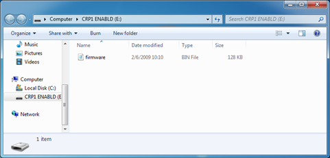 Fig. 7.
Reconnect device and check firmware version. It should now represent the one it was updated to.
Testing With “THE VINCI” software
To test IOMOD HT with default settings, user can connect device through RS485 to Modbus or IEC-60870 (depending on firmware) master or using USB Simulation Mode. Example will show The Vinci Expert as serial interface converter and adapter to PC with The Vinci software. Default settings – 9600 baud; 8 databits, none parity, 1 stop bit. When opening The Vinci software, choose Modbus serial – Master mode. In Settings tab, choose Slave address (default – 1); configure a job as shown in Figure 8 and set the tag names to the created job if needed; the presented values are multiplied by 10 as mentioned before. Press Start and go to the Statistic tab.
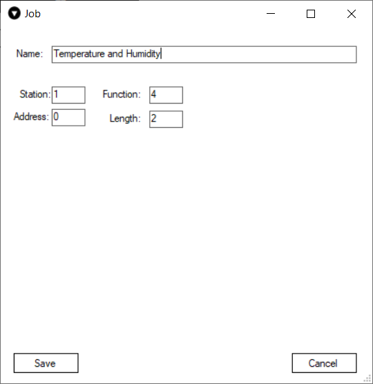 Fig. 8.
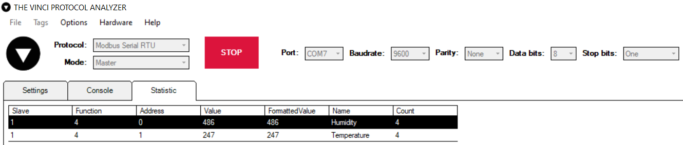 Fig. 9. Basic version example
Downloads
Configuration example download for IOMod HT basic -> iomod_HT_Modbus_to_IEC104_SCADA.xlsx
Configuration example download for IOMod HT advanced -> iomod_HT_advanced_Modbus_to_IEC104_SCADA.xlsx
IOMOD HT Modbus firmware ->IOMOD_MODBUS_v1_24_4.bin
IOMOD HT User Manual IEC 60870-5-103
Introduction
IOMOD HT is used for temperature and humidity data monitoring over Modbus (RTU), IEC 60870-5-103 or IEC 60870-5-101. Advanced version of the device is also capable of switching relays automatically (thermostat function) as configured.
Features
- Temperature measurement in 0.1°C resolution
- Humidity measurement in 0.1% resolution
- Modbus, IEC-60870-5-103 and IEC-60870-5-101 communication over RS485
- 2 normally open relay outputs (advanced version)
- Automatically configurable relay switching on temperature or humidity change
- Configuration over USB console
- Drag and Drop firmware upgrade over USB mass storage
- LED indication for input/output and data transmission
- Spring contact connectors
- Easy connection with WCC Lite gateway and CloudIndustries.eu platform
Operational Information
IOMOD uses Modbus (RTU) or IEC-60870-103 or IEC-60870-101 protocols over RS485 connection, which can be used with cable length up to 1500 meters and connect up to 30 devices on one line. Default IEC 60870-5-103 settings are: 9600 baudrate, 8 databits, E parity, 1 stopbit , Slave address - 1.
To read temperature and humidity, user can use device with default settings without configuring it. To read humidity, set info number to 0. To read temperature, set info number to 1.
To enable thermostat function, user can configure device over USB or over MODBUS. Configurable options are shown in table below.
| CONFIGURABLE OPTIONS | OVER USB | OVER MODBUS |
| Slave Address | Yes | No |
| Baudrate | Yes | No |
| Data, Stop and Parity bits | Yes | No |
| RS485 Terminating Resistor | Yes | No |
| 1st Relay active mode | Yes | Yes |
| 1st Relay active range | Yes | Yes |
| 2nd Relay active mode | Yes | Yes |
| 2nd Relay active range | Yes | Yes |
| Default Settings | Yes | No |
PWR LED
Green - Normal operation, device is powered correctly.
RX/TX LED
The RX/TX LED on the IOMod flashes when data is either being transmitted or received via the RS485 port.
IEC 60870-5-103 working information
Initialization
IOmod uses a standard IEC-60870-5-103 communication scheme. Initiation, control messages and queries are initiated by the master (controlling station), while IOmod device (controlled station) only answers these requests. Therefore, the first message should be sent by master to start/restart communication (7 (RESET CU or LINK RESET FCB). This message is answered by IOmod with an acknowledgement (ACK) to enable master to proceed with sending other messages defined by IEC- 60870-5-103 protocol. Other messages are ignored until a successful initialization has taken place.
Data polling
When initialization is complete, master may poll IOmod device with both Class 1 and Class 2 requests. Class 2 is used when master polls for a cyclic data. Controlled device answers with a message containing Access Demand flag when spontaneous data exists and master then sends request for Class 1. IOmod would then respond with time-tagged message.
On first Class 1 request IOmod device always asks for the Access Demand to send an identification string. However, if there are spontaneous messages to be sent, they will be sent before the identification string.
Output control
To control device outputs master (controlling station) sends command conforming to the IEC-60870-5-103 protocols. It should contain output address which is 160 by default. Info number 0 represents humidity, 1 is temperature, 2 - communication error (this applies for basic version). Successful command is accepted with a positive acknowledge. Negative acknowledge is returned if the output is already set or if another command for the same output is already in progress and hasn’t finished yet.
Sensor messages
When sensor status changes, IOmod device filters input glitches through filters with a user configurable filter time. When the filter is passed device sends message with “Function type” as input address (default function type of inputs – 255), and “Info number” as input pin number.
Time synchronization
To initiate the time synchronization between devices master must send variable frame, with function code “User data with ACK”, ASDU type “6” and Cause of Transmission “8”. Info elements must contain the 7- byte time structure.
As per IEC-60870-5-103 protocol specification time synchronization can be completed for multiple devices using broadcasting messages. It is included in IEC-60870-5-103 firmware since version 1.7.3. To broadcast time synchronization message, link address should be equal to 255.
General interrogation
General Interrogation (GI) is initiated by the master with variable frame, including function code “3” (User data with ACK), ASDU type “7” and Cause of Transmission “9”. Slave device then responds with an acknowledgement (ACK). Master gets GI data by polling with Class 2 request till slave transmits “End of GI” (Cause of Transmission – “10”). IOmod device responds with a time-tagged message, including DPI states of inputs and outputs (Outputs are sent first). Output and input numbers are represented by “Info number” in protocol.
Technical information
| System | ||
| Dimensions | 26 (H) x 71 (W) x 71 (L), mm | |
| Case | ABS, white | |
| Working environment | Indoors | |
| Working temperature | -20 ÷ +70 °C | |
| Recommended operating conditions |
5 – 60 °C and 20 – 80 %RH; | |
| Configuration | USB | |
| Firmware upgrade | USB – mass storage device | |
| Electrical Characteristics | Basic | Advanced |
| Termination Resistor | Selectable 120 Ω | Selectable 120 Ω |
| Power supply | 12-24 VDC, 8 mA (nominal); 5-33 VDC (full range) | 24 VDC, 25 mA (nominal); 18-27 VDC (full range) |
| Relays | - | 2 (Normally Open); |
| Relay specifications | Basic | Advanced |
| Resistive load (cosφ=1) | - | 5 A at 250 VAC, 5 A at 30 VDC |
| Inductive load (cosφ=0.4, L/R=7ms) | - | 2 A at 250 VAC, 2 A at 30 VDC |
| Max. switching power | - | 1,250 VA, 150 W |
Device Connection
IOMOD HT has integrated 120 Ω termination resistor which can be enabled or disabled over USB configuration. It is recommended to use termination at each end of the RS485 cable. See typical connection diagram on Fig. 1.
Fig. 1.
Figure 2 shows explanation on device connection.
Fig. 2.
Configuration over USB
Driver installation
Device requires USB drivers to work as a Virtual COM port. First-time connection between device and computer could result in “Device driver software was not successfully installed” error such as one shown in Fig. 3.
Fig. 3.
A user then should manually install drivers by selecting a downloaded driver folder:
- Go to Control Panel -> Device Manager;
- Select a failing device;
- Press “Update driver software”; screen as in Fig. 4 should appear:
Fig. 4.
- Select “x86” driver for a 32-bit machine or x64 for a 64-bit machine. If not sure, select a root
folder (folder in which x64 and x86 lay inside, as in Fig. 5).
IOMod HT configuration via PuTTY terminal
Configuration of IOMOD device is done through CLI (Command Line Interface) on virtual COM port. Drivers needed for MS Windows to install VCOM will be provided. To open up CLI simply connect to specific VCOM port with terminal software (it is advised to use PuTTY terminal software. If other software is being used, user might need to send <return> symbol after each command). When connected user should immediately see main screen similar to one in Fig. 6.
Fig. 6.
If terminal window is accidentally closed without exiting, user can connect to terminal again, and press any key on keyboard to show up main menu once again.
Configuration of device is not possible when USB Simulation Mode is entered. To access configuration menu again user should reset device and then try again.
|
Menu Name |
Function |
Values |
Default Values |
|
|
1. |
Link Address |
Setts Link address |
1-255 |
1 |
|
2. |
Baudrate, Parity and stop bits |
Enters configuring screen for communication settings |
[1] Set 8 Data bits + 1 Stop bit |
[3] 9600, 8 Data bits + 1 Stop bit, [4] Parity - Even |
|
3. |
Data addressing config |
Enters configuring screen for Input/ Output address (function type) |
[4] Configure analog inputs' function type [255] |
[4] 255 [5] 160 |
|
4. |
RS485 Terminating Resistor |
RS485 120 Ohms Terminating Resistor |
[1] Enable [2] Disable |
Disabled |
|
7. |
Set Default Settings |
Sets Default Settings |
[1] Confirm [0] Cancel |
- |
|
8. |
Firmware Upgrade |
Mass Storage Device Firmware Upgrade |
[1] Confirm [0] Cancel |
- |
|
9. |
Diagnostics |
Input / Output states |
[] Refresh [9] Enter USB protocol simulator mode [0] Back |
- |
|
0. |
Exit |
Exit and disconnect |
- |
- |
IOMOD HT Advanced IEC 60870-5-103 main menu
| Main Menu | Function | Values | Default Values | |
|
1. |
Link Address |
Setts Link address |
1-255 |
1 |
|
2. |
Baudrate, Parity and stop bits |
Enters configuring screen for communication settings |
[1] Set 8 Data bits + 1 Stop bit |
[3] 9600, 8 Data bits + 1 Stop bit, [4] Parity - Even |
|
3. |
Data addressing config |
Enters configuring screen for Input/ Output address (function type) |
[4] Configure analog inputs' function type [255] |
[4] 255 [5] 160 |
|
4. |
RS485 Terminating Resistor |
RS485 120 Ohms Terminating Resistor |
[1] Enable [2] Disable |
Disabled |
| 5. | Relay #1 settings | Active mode and active range | Active mode: 1 –Relay disabled; 2- Temperature active 3- Humidity active; active range: -10 to 60 (temperature) and 0 to 100 (humidity) | 0 |
| 6. | Relay #2 settings | Active mode and active range | Active mode: 1 –Relay disabled; 2- Temperature active 3- Humidity active; active range: -10 to 60 (temperature) and 0 to 100 (humidity) | 0 |
|
7. |
Set Default Settings |
Sets Default Settings |
[1] Confirm [0] Cancel |
- |
|
8. |
Firmware Upgrade |
Mass Storage Device Firmware Upgrade |
[1] Confirm [0] Cancel |
- |
|
9. |
Diagnostics |
Input / Output states |
[] Refresh [9] Enter USB protocol simulator mode [0] Back |
- |
|
0. |
Exit |
Exit and disconnect |
- |
- |
Firmware upgrade over USB
To update device firmware user must enter main configuration menu.
Enter Firmware update screen by pressing [8];
Confirm update by pressing [1];
User then must delete existing file “firmware.bin”, and simply upload new firmware file by drag and drop, Fig. 7.
Fig. 7.
Reconnect device and check firmware version. It should now represent the one it was updated to.
Testing With “THE VINCI” software
To test IOMOD HT with default settings, user can connect device through RS485 to Modbus or IEC-60870 (depending on firmware) master or using USB Simulation Mode. Example will show The Vinci Expert as serial interface converter and adapter to PC with The Vinci software. Default settings – 9600 baud; 8 databits, even parity, 1 stop bit. When opening The Vinci software, choose IEC 60870-5-103 – Master mode; press Start and go to Statistic tab; the lower value is temperature.
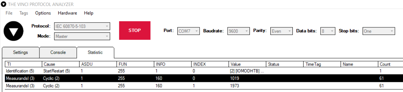
Fig. 8. Basic version example.
The presented values should be multiplied by 0.02442002442, because as of now the IOMOD uses the following equation to calculate a value in a register: x/4095*100; x is the presented value, 1019 and 1973 in Figure 8. 1019 is equal to 24.88 °C and 1973 is 48.18 %RH.
Configuration example download -> iomod_HT_IEC103_to_IEC104_SCADA.xlsx
IOMOD HT User Manual IEC 60870-5-101
Introduction
IOMOD HT is used for temperature and humidity data monitoring over Modbus (RTU), IEC 60870-5-103 or IEC 60870-5-101. Advanced version of the device is also capable of switching relays automatically (thermostat function) as configured.
Features
- Temperature measurement in 0.1°C resolution
- Humidity measurement in 0.1% resolution
- Modbus, IEC-60870-5-103 and IEC-60870-5-101 communication over RS485
- 2 normally open relay outputs (advanced version)
- Automatically configurable relay switching on temperature or humidity change
- Configuration over USB console
- Drag and Drop firmware upgrade over USB mass storage
- LED indication for input/output and data transmission
- Spring contact connectors
- Easy connection with WCC Lite gateway and CloudIndustries.eu platform
Operational Information
IOMOD uses Modbus (RTU) or IEC-60870-103 or IEC-60870-101 protocols over RS485 connection, which can be used with cable length up to 1500 meters and connect up to 30 devices on one line. Default IEC 60870-5-101 settings are: 9600 baudrate, 8 databits, E parity, 1 stopbit , Slave address - 1.
To read temperature and humidity, user can use device with default settings without configuring it. To enable thermostat function, user can configure device over USB or over MODBUS. Configurable options are shown in table below.
| CONFIGURABLE OPTIONS | OVER USB | OVER MODBUS |
| Slave Address | Yes | No |
| Baudrate | Yes | No |
| Data, Stop and Parity bits | Yes | No |
| RS485 Terminating Resistor | Yes | No |
| 1st Relay active mode | Yes | Yes |
| 1st Relay active range | Yes | Yes |
| 2nd Relay active mode | Yes | Yes |
| 2nd Relay active range | Yes | Yes |
| Default Settings | Yes | No |
PWR LED
Green - Normal operation, device is powered correctly.
RX/TX LED
The RX/TX LED on the IOMod flashes when data is either being transmitted or received via the RS485 port.
IEC 60870-5-101 working information
Initialization
IOmod uses a standard IEC-60870-5-101 communication scheme. Initiation, control messages, and queries are initiated by the master (controlling station), while the IOmod device (controlled station) only answers these requests. Therefore, the first message should be sent by the master to request status of link (function code = 9). This message is answered by IOmod with the status of link (function code = 11) if link is available. Otherwise there is going to be no response. After receiving the status of link the master will send Reset of remote link command (function code = 0) to restart the communication. The IOMod can respond with either acknowledgment (function code = 0, ACK) or Negative Acknowledgment (function code = 1, NACK). If IOMod respond is ACK then the initialization procedure is finished. The described procedure enables the master to proceed with sending other messages defined by the IEC-60870-5-101 protocol.
Data polling
When initialization is complete, the master may request data from the IOmod device with general interrogation. Although according to the protocol specification IOMod will send data on value change, the HT IOMod responds with type 30 (M_SP_TB_1) a single point value with a time tag.
Output control
To control device outputs master (controlling station) sends a command conforming to the IEC-60870-5-101 protocols. Negative acknowledge is returned if the sent command isn't configured. For example wrong address or type.
Sensor messages
When input status changes, IOmod device filters input glitches through filters with a user-configurable filter time. When the filter is passed device sends a message with the 36 data type (M_ME_TF_1) if the measurements type is float, if it is integer, the device sends a message with the 34 data type (M_ME_TD_1),
Time synchronization
To initiate the time synchronization between devices the master must send a Clock Sync command. The command type is C_CS_NA_1 (103) and the Cause of Transmission (COT) has to be 6. The command has to be sent to the correct link address and CASDU, which is the same as the link address by default. If the sent frame is correct the IOMod will respond with a C_CS_NA_1 (103) type command with the COT (cause of transmission) of 7 and the p/n bit will be positive (0) also the command will be time-tagged with the device time. If the time synchronization feature is disabled or the command is sent to an undefined CASDU the response is the same except the p/n bit will be negative (1).
General interrogation
General Interrogation (GI) is initiated by the master sending the General Interrogation command. The command type is C_IC_NA_1 (100) and the Cause of Transmission (COT) has to be 6. The command has to be sent to the correct link address and CASDU, which is the same as the link address by default. If the sent frame is correct the IOMod will respond with a C_IC_NA_1 (103) type command with the COT (cause of transmission) of 7 and the p/n bit will be positive (0). Otherwise, it will respond with the same command just that the p/n bit will be negative (1). Then the device will begin to send all of its data. After that's done the IOMOD will also send another 100 type command with the COT (cause of transmission) of 10 (ActTerm) meaning the general interrogation is over.
Technical information
| System | ||
| Dimensions | 26 (H) x 71 (W) x 71 (L), mm | |
| Case | ABS, white | |
| Working environment | Indoors | |
| Working temperature | -20 ÷ +70 °C | |
| Recommended operating conditions |
5 – 60 °C and 20 – 80 %RH; | |
| Configuration | USB | |
| Firmware upgrade | USB – mass storage device | |
| Electrical Characteristics | Basic | Advanced |
| Termination Resistor | Selectable 120 Ω | Selectable 120 Ω |
| Power supply | 12-24 VDC, 8 mA (nominal); 5-33 VDC (full range) | 24 VDC, 25 mA (nominal); 18-27 VDC (full range) |
| Relays | - | 2 (Normally Open); |
| Relay specifications | Basic | Advanced |
| Resistive load (cosφ=1) | - | 5 A at 250 VAC, 5 A at 30 VDC |
| Inductive load (cosφ=0.4, L/R=7ms) | - | 2 A at 250 VAC, 2 A at 30 VDC |
| Max. switching power | - | 1,250 VA, 150 W |
Device Connection
IOMOD HT has integrated 120 Ω termination resistor which can be enabled or disabled over USB configuration. It is recommended to use termination at each end of the RS485 cable. See typical connection diagram on Fig. 1.
Fig. 1.
Figure 2 shows explanation on device connection.
Fig. 2.
Configuration over USB
Driver installation
Device requires USB drivers to work as a Virtual COM port. First-time connection between device and computer could result in “Device driver software was not successfully installed” error such as one shown in Fig. 3.
Fig. 3.
A user then should manually install drivers by selecting a downloaded driver folder:
- Go to Control Panel -> Device Manager;
- Select a failing device;
- Press “Update driver software”; screen as in Fig. 4 should appear:
Fig. 4.
- Select “x86” driver for a 32-bit machine or x64 for a 64-bit machine. If not sure, select a root
folder (folder in which x64 and x86 lay inside, as in Fig. 5).
IOMod HT configuration via PuTTY terminal
Configuration of IOMOD device is done through CLI (Command Line Interface) on virtual COM port. Drivers needed for MS Windows to install VCOM will be provided. To open up CLI simply connect to specific VCOM port with terminal software (it is advised to use PuTTY terminal software. If other software is being used, user might need to send <return> symbol after each command). When connected user should immediately see main screen similar to one in Fig. 6.
Fig. 6.
If terminal window is accidentally closed without exiting, user can connect to terminal again, and press any key on keyboard to show up main menu once again.
Configuration of device is not possible when USB Simulation Mode is entered. To access configuration menu again user should reset device and then try again.
|
Menu Name |
Function |
Values |
Default Values |
|
|
1. |
Link Address |
Setts Link address |
1-255 |
1 |
|
2. |
Baudrate, Parity and stop bits |
Enters configuring screen for communication settings |
[1] Set 8 Data bits + 1 Stop bit |
[3] 9600 baudrate, 8 Data bits + 1 Stop bit, [4] Parity - Even |
|
3. |
RS485 Terminating Resistor |
RS485 120 Ohms Terminating Resistor |
[1] Enable [2] Disable |
Disabled |
|
6. |
Protocol settings |
Change specifitc protocol options |
[1] Toggle 24/56 bit time [0] Back |
[1] 56 bit |
|
7. |
Set Default Settings |
Sets Default Settings |
[1] Confirm [0] Cancel |
- |
|
8. |
Firmware Upgrade |
Mass Storage Device Firmware Upgrade |
[1] Confirm [0] Cancel |
- |
|
9. |
Diagnostics |
Input / Output states |
[] Refresh [9] Enter USB protocol simulator mode [0] Back |
- |
|
0. |
Exit |
Exit and disconnect |
- |
- |
IOMOD HT Advanced IEC 60870-5-101 main menu
| Main Menu | Function | Values | Default Values | |
|
Menu Name |
Function |
Values |
Default Values |
|
|
1. |
Link Address |
Setts Link address |
1-255 |
1 |
|
2. |
Baudrate, Parity and stop bits |
Enters configuring screen for communication settings |
[1] Set 8 Data bits + 1 Stop bit |
[3] 9600 baudrate, 8 Data bits + 1 Stop bit, [4] Parity - Even |
|
3. |
RS485 Terminating Resistor |
RS485 120 Ohms Terminating Resistor |
[1] Enable [2] Disable |
Disabled |
| 4. | Relay #1 settings | Active mode and active range | Active mode: 1 –Relay disabled; 2- Temperature active 3- Humidity active; active range: -10 to 60 (temperature) and 0 to 100 (humidity) | 0 |
| 5. | Relay #2 settings | Active mode and active range | Active mode: 1 –Relay disabled; 2- Temperature active 3- Humidity active; active range: -10 to 60 (temperature) and 0 to 100 (humidity) | 0 |
|
6. |
Protocol settings |
Change specifitc protocol options |
[1] Toggle 24/56 bit time [0] Back |
[1] 56 bit |
|
7. |
Set Default Settings |
Sets Default Settings |
[1] Confirm [0] Cancel |
- |
|
8. |
Firmware Upgrade |
Mass Storage Device Firmware Upgrade |
[1] Confirm [0] Cancel |
- |
|
9. |
Diagnostics |
Input / Output states |
[] Refresh [9] Enter USB protocol simulator mode [0] Back |
- |
|
0. |
Exit |
Exit and disconnect |
- |
- |
Firmware upgrade over USB
To update device firmware user must enter main configuration menu.
Enter Firmware update screen by pressing [8];
Confirm update by pressing [1];
User then must delete existing file “firmware.bin”, and simply upload new firmware file by drag and drop, Fig. 7.
Fig. 7.
Reconnect device and check firmware version. It should now represent the one it was updated to.
Testing With “THE VINCI” software
To test IOMOD HT with default settings, user can connect device through RS485 to Modbus or IEC-60870 (depending on firmware) master or using USB Simulation Mode. Example will show The Vinci Expert as serial interface converter and adapter to PC with The Vinci software. Default settings – 9600 baud; 8 databits, even parity, 1 stop bit. When opening The Vinci software, choose IEC 60870-5-101 – Master mode. In Settings tab, change the IAO size in bytes to 1, as that is the default setting; configure a tag as shown in Fig. 8 (floating type is 36, integer type is 34); press Start and go to Statistic tab.
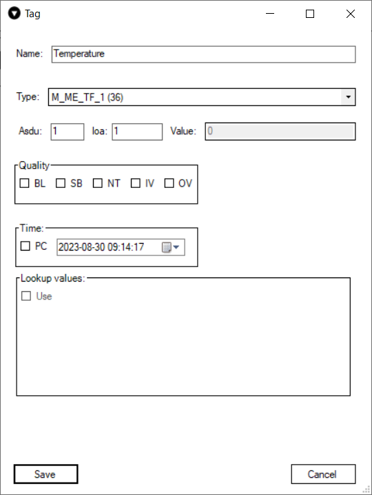
Fig. 8.
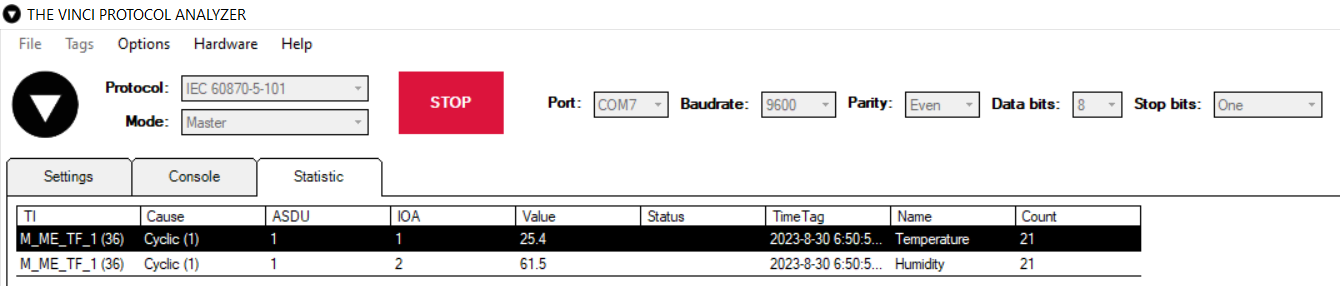 Fig. 9. Basic version example.
Floating measurements type represents the exact value of the registers, integer measurements type is multiplied by 10. To counter that the user must multiply the signals values by 0.1 in the configuration file.
This manual applies to IOMod FW versions 1.0.5 or newer -> iomod_iec101_v1.0.5.bin
Configuration example download -> iomod_HT_IEC101_to_IEC104_SCADA.xlsx