IOMOD 8DI4RO
IOMod 8DI4RO – industrial 8 digital inputs and 4 relay outputs module.
- Firmware version 1
- IOMOD 8DI4RO User Manual Modbus
- IOMOD 8DI4RO User Manual IEC 60870-5-103
- IOMOD 8DI4RO User Manual IEC 60870-5-101
- Firmware version 2
Firmware version 1
IOMOD 8DI4RO User Manual Modbus
Introduction
IOMod 8DI4RO is a small-size stand-alone Modbus RTU, IEC 60870-5-103 or IEC-60870-5-101 digital input and relay output controller (protocol depends on firmware). IOmod can be used for industrial applications, where digital signaling is used and robust communication is needed. IOmod is an ideal solution for applications such as data acquisition, control, and process monitoring at remote places. This user manual is written for Modbus protocol firmware version.
Features
-
8 digital inputs;
-
Configurable active input signal polarity or input inversion;
-
4 relay outputs;
-
Galvanically isolated inputs and outputs;
-
Pulsed or latched mode for individual outputs;
-
Possible output feedback measurement with inputs;
-
Configuration over USB console or MODBUS RTU;
-
Values with data and time information;
-
Drag and Drop firmware upgrade over USB mass storage;
-
Modbus RTU, IEC-60870-5-103, IEC-60870-5-101 communication over RS485;
- Software selectable RT 120 Ohm termination resistor on RS485 interface;
-
LED indication for input/output and data transmission;
-
Easy integration with WCC Lite gateway and CloudIndustries.eu platform;
Operational information
IOmod 8DI4RO uses Modbus RTU, IEC 60870-5-103, or IEC 60870-5-101 protocol to communicate with a master device over RS485 interface. Protocol used by the device can be changed by uploading the corresponding firmware.
Status LED
Status LED can be in 2 colors :
Blue - Device connected to USB.
Green - Normal operation.
Rx/Tx LED
The RX/TX LED on the IOMod flashes when data is either being transmitted or received via the RS485 port.
MODBUS operational information
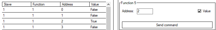
To read output status, send 01 Modbus command (Read Coils) with address of the first register (0) and displacement of 4. Returned value will show all 4 output states (1 - turned On, 0 - turned Off).
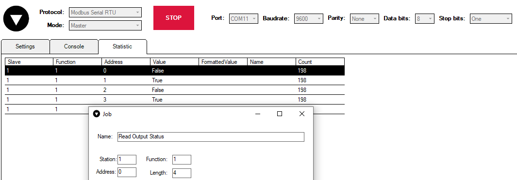
The fourth byte in 8DI4RO respond shows the status of outputs (0A = 0000 1010, means that RO2 and RO4 outputs are turned on).

To read input status, send 02 Modbus command (Read Discrete Inputs) with address of first register (0), and displacement of 8. Returned value will show 8 input states.
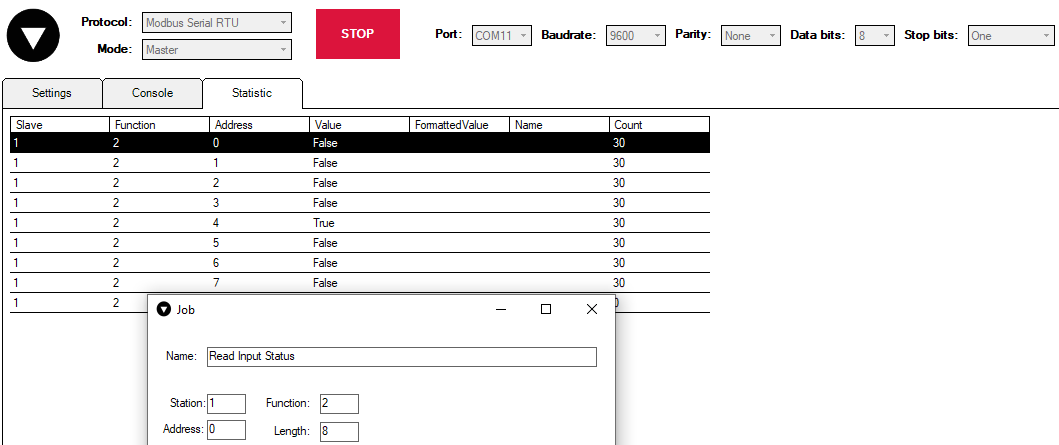
The fourth byte in 8DI4RO respond shows the status of outputs (10 = 0001 0000, means that fifth input is turned on).

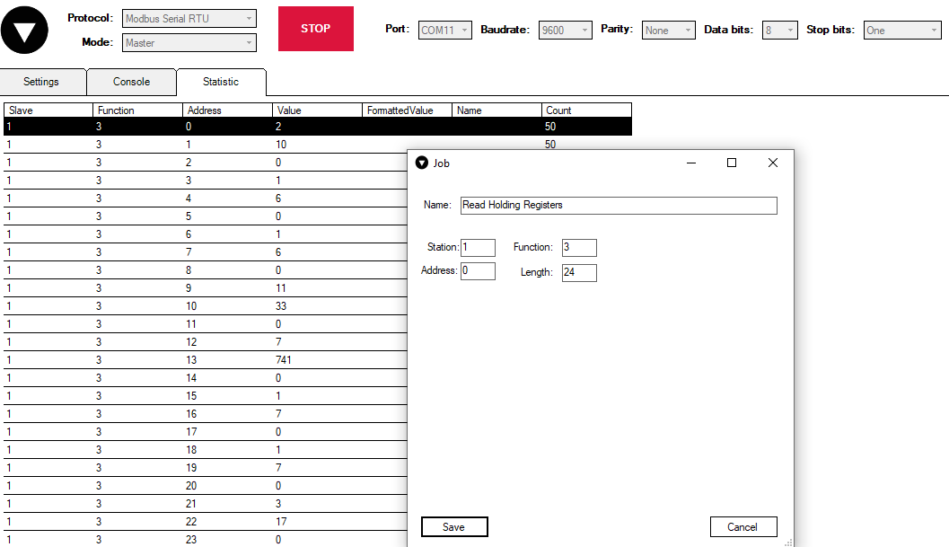
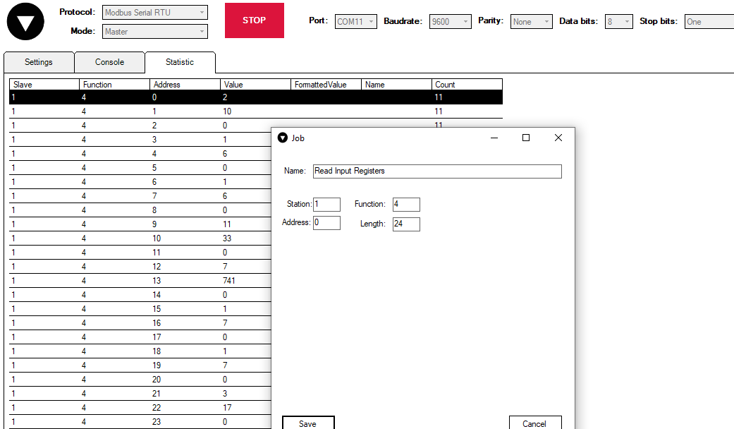
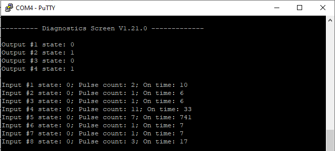
To read input counter values, send 03 Modbus command (Read Holding Registers) or 04 Modbus command (Read Input Registers) with resolution of first register (0) and size of 24. Returned data will show pulse count (first register) and ON time (2nd and 3rd registers) for each input – pulse count of input #2 will be at register 4th, and so on. ON time will be shown as seconds.
Function 3:
Function 4:
Values can be compared with values in Diagnostics Screen in Putty application (this interface will be discussed later):
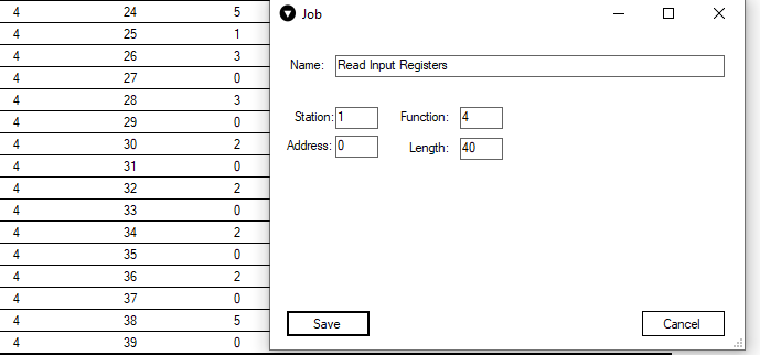
ON time and pulse count will increase when input pulse is longer than Filter time, which is configured by user in USB terminal menu. Shorter pulses will be ignored in both pulse and ON time registers. From software version 1.10, as capacity of input counter expanded to 32-bits, additional 16 registers depict such wider values in registers 00023-00039. That means that function 3 and 4 commands can be sent with length 40 specified. Then 24-39 registers are going to display only pulse count values:
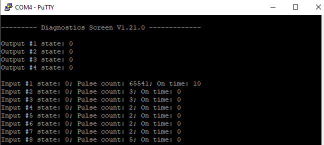
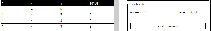
Two registers are allocated for each pulse count value. If value of pulse count becomes more than 65535 then second register comes into use. The values above can be compared with values from diagnostics screen:
These input counter values can be changed by using 06 Modbus command.

To turn single output on or off, send command 05 (Write Single Coil), with output address (0 to 3). To turn output on – send hex value FF00; to turn off – hex value 0000.

To turn multiple outputs on or off, use command 15 (Write Multiple Coils), and send binary coded value for 4 coils at address (0) and length 4.
To invert input states by software configure device over USB terminal. Useable Modbus commands shown in table below.
Supported MODBUS functions
01 (0x01) Read Coil Status
Reads status of relays (Off or On). IOMOD 8DI4RO has 4 relay outputs from address 0 to address 3.
02 (0x02) Read Discrete Inputs
Reads status of digital inputs (Off or On). IOMOD 8DI4RO has 8 digital inputs from address 0 to address 7. These inputs are active-high by default.
03 (0x03) Read Holding Registers
Lets user read counter/timer values dedicated to digital inputs. There are 40 MODBUS registers. Values held in these registers are explained in a table below. There are two types of values - Pulse Counter and On Timer, the latter calculating the time that respective input was held in its active state.
04 (0x04) Read Input Registers
Lets user read counter/timer values dedicated to digital inputs. There are 80 MODBUS registers. Values held in these registers are explained in a table below. There are two types of values - Pulse Counter and On Timer, the latter calculating the time in seconds that respective input was held in its active state. This function is deprecated and mirrors function 0x03 to conform to past versions of IOMOD 16DI.
05 (0x05) Write Single Coil
Sets a single relay output On or Off. Output addresses from 0 to 3 (first output – address 0, last output – address 3).
06 (0x06) Preset Single Register
Sets a single register. Register addresses is identical to “Read Input Registers” addresses.
15 (0x0F) Write Multiple Coils
Sets multiple relay output On or Off. Output addresses from 0 to 3 (first output – address 0, last output – address 3).
Modbus register mapping table
| Register | Description | Value range |
| Read coil status (01) | ||
| 00000-00007 | Reading digital outputs RO1-RO4 |
0-255 |
| Read discrete inputs (02) | ||
| 00000-00007 | Reading digital inputs DI1-DI8 |
0-255 |
| Read holding register (03), Read input register (04), Preset Single Register (06) | ||
| 00000 | Pulse count for DI1, Least Significant Word |
0-65535 |
| 00001-00002 | On-time in seconds for DI1, Least Significant Word first* | 0-65535 |
| ... | ... | ... |
| 00021 | Pulse count for DI8, Least Significant Word | 0-65535 |
| 00022-00023 | On-time in seconds for DI8, Least Significant Word first* | 0-65535 |
| 00024-00039 | Pulse count for DI1-DI8, Least Significant Word first* | 0-65535 |
| Write single coil (05) | ||
| 00000-00003 | Writing a single relay output | 0x0000 / 0xFF00 |
| Write multiple coils (15) | ||
| 00000-00003 | Writing multiple relay outputs RO1-RO4 | 0-255 |
*It is advised to set most significant word of counter/timer first
Device configuration
Input inversion and polarity selection
Unlike 8DI8DO IOmod 8DI4RO does not have pull-up resistors. If user desires to turn input status on, when that input signal is low, user then inverts inputs logically. All input indication LED’s stay the same (are not inverted).
Input / Output grouping
Sometimes two inputs or two outputs must be captured as one DPI input or output. Inputs and outputs can be grouped into the pairs of two. This allows outputs to be controlled by one DPI command (of address of first output in the group). Only two neighbor pins can be grouped into pair, while first pin in pair must be an odd number pin. When grouped, second pin in the pair is not used anymore – all requests for this pin generate an error. For example – RO1.1-2 and RO2.1-2 can be grouped, after that RO2.1-2 is not used; RO2.1-2 and RO3.1-2 cannot be grouped; RO3.1-2 and RO4.1-2 can be grouped, but RO4.1-2 is not used then, etc.
Fig. 1. picture shows outputs and inputs ungrouped and controlled independently. In this mode, General Interrogation will be composed of 4 output states and 8 input states.
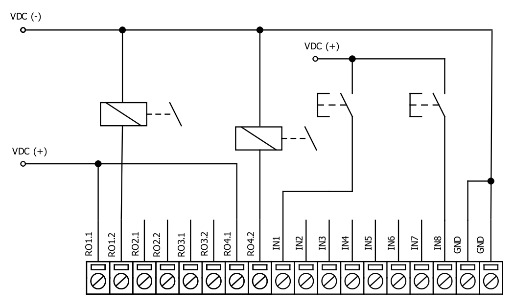
Fig. 1.
Let's consider a situation shown in Fig. 2. In the picture below first two relay outputs are grouped into pair. Also 3rd and 4th inputs are grouped into pair. Now, General interrogation will be composed of 3 output states (with RO2.1-2 missing), and 7 input states (with IN4 missing). Output and input numbers is represented by “Info number” in protocol.
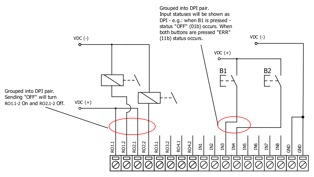
Fig. 2.
Input filter
Input filter is a simple glitch filter with time input. This filter time corresponds to stable time that input must achieve before sending a status change.
Output pulse time
User can configure outputs to be pulse controlled – it means that output will be turned on for configured amount of time. When this time runs out, output is turned off. This is useful when pulse toggle relays are used. Output pulse is independent from output grouping option and can be used on both grouped and ungrouped outputs. When output is grouped, device will allow only one command completion at a time – when output is already turned ON, other “turn ON” requests will be responded with NACK. If user desires latching outputs to be used, output pulse time is set to 0.
In the picture below is depicted an example of pulse output usage. Inputs and outputs are grouped, and output pulse time is set to 1s. When user sends ON command, RO2.1-2 are pulsed for 1s, and relay is set. This will connect NO contact and IN2 will turn on (assuming it is not inverted). When user sends OFF command, RO1.1-2 are pulsed, and relay is reset, turning IN1 on.
Output detection with inputs
Users can detect an output change with inputs.
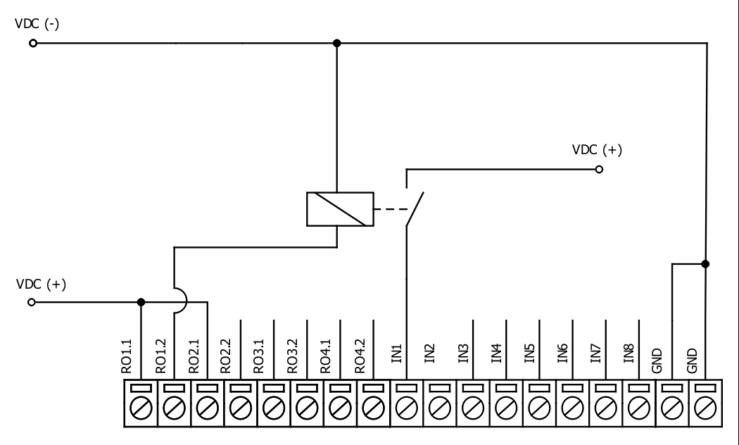
Fig. 3.
To find out if relays are turned on, user can connect relay outputs to IOmod inputs (maximum allowed voltage must be taken into account). When relays are turned on, device responds with IEC-60870-5-101 protocol message “Remote Operation”. If inputs are never turned on or off, device will send “Remote Operation” message after time-out period, with current input statuses. Time-out period is configured by user as a Feedback Time.
Technical information
|
|
System |
|
|
1. |
Dimensions |
101 x 119 x 22.5 mm |
| 2. |
Case |
IP20, blend PC/ABS self-extinguishing, black |
|
3. |
Working environment |
Indoors |
|
4. |
Operating temperature |
from -30°C to +70°C |
|
5. |
Humidity |
5-95% RH (non-condensing) |
|
6. |
Configuration |
USB – serial console, MODBUS RTU |
|
7. |
Firmware upgrade |
USB – mass storage device |
|
|
Electrical specifications |
|
|
|
Inputs |
|
|
8. |
Nominal input voltage range |
12-48VDC |
|
9. |
Isolation |
8 X 3kV(rms) |
|
10. |
Maximum input voltage |
60VDC |
|
|
Output relay contacts ratings |
|
|
11. |
Isolation |
4 X 3kV(rms) |
|
12. |
Rated resistive load |
5 A (at 250 VAC or at 30 VDC) |
|
13. |
Rated inductive (L/R=7ms) load |
2 A (at 250 VAC or at 30 VDC) |
|
14. |
Maximum switching voltage |
277 VAC 125 VDC |
|
15. |
Maximum switching current |
5 A |
|
|
Power |
|
|
16. |
Power Supply |
12-24 VDC / 9-33 VDC (full range) |
|
17. |
Current consumption |
70 mA |
In the Fig. 5. you can see internal structure of 8DI4RO IOmod. An important fact to metion is that as it can be noticed in the scheme below all inputs are isolated. However ground connection is common for all phototransistors.

Fig. 4.
Mounting and installation guide
IOmod 8DI4RO RS485 interface
IOmod 8DI4RO has an integrated 120Ω termination resistor which can be enabled or disabled over USB configuration. It is recommended to use termination at each end of the RS485 cable. See typical connection diagram on Fig. 6.
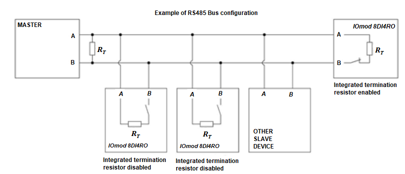
Fig. 5.
IOmod 8DI4RO has 1/8 Unit load receiver which allows to have up to 256 units on line (compared to standard 32 units). To reduce reflections, keep the stubs (cable distance from main RS485 bus line) as short as possible when connecting device.
IOmod 8DI4RO inputs
Typical application of IOmod 8DI4RO inputs is shown on Fig. 2. When default configuration for inputs is applied, user will see inputs connected to +12-24V as “high” or state “1” and input status LED will glow.
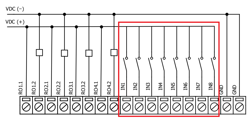
Fig. 6.
User also can configure to enable software input inversion. With this configuration, user will see inputs connected to 0V (see Fig. 3.) as “high” or state “1”, input status LED will NOT glow.
IOmod 8DI4RO outputs
IOmod 8DI4RO has 4 relay outputs. Internal clamp diodes are connected to each output which makes IOmod 8DI4RO ideal for driving inductive loads like relays. Maximum 5A per output is allowed. For higher loads outputs can be connected in parallel. Make sure your power supply can provide enough power. Typical application of outputs is shown on Fig. 4.
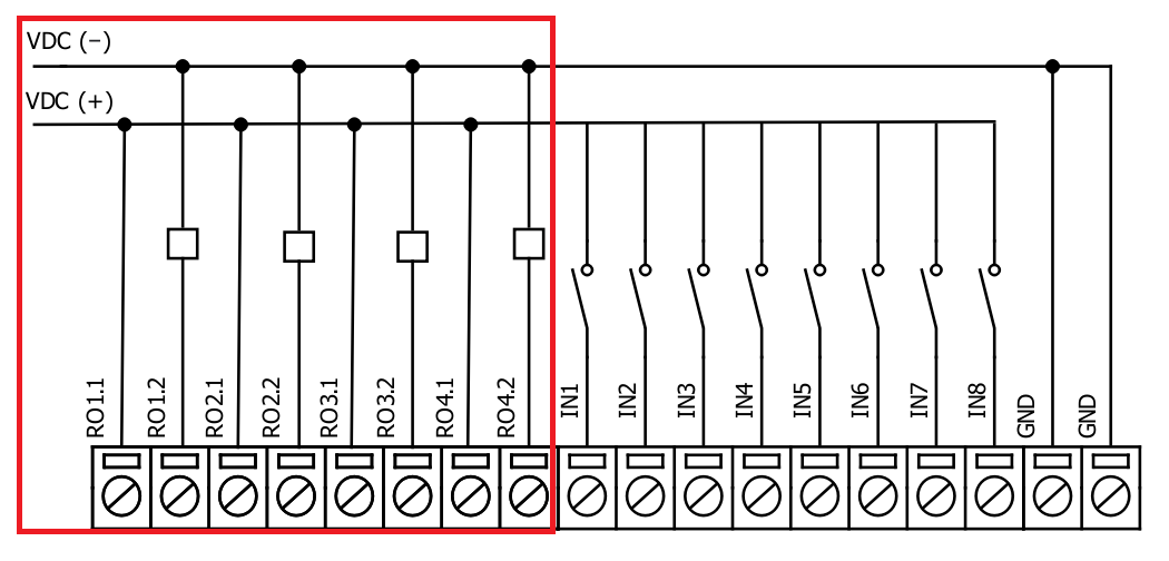
Fig. 7.
Configuration over USB
Driver installation
Device requires USB drivers to work as a Virtual COM port. First-time connection between device and computer could result in “Device driver software was not successfully installed” error (Fig. 5.).
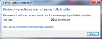
Fig. 8.
Drivers can be installed from Wiki Esleseta -> Downloads -> IOMOD Series Downloads-> Firmware and tools -> IOMOD USB drives for Windows;
User then manually installs drivers by selecting downloaded driver folder:
Go to Control Panel -> Hardware and Sound -> Device Manager
Select failed device;
Press “Update driver software”; screen in Fig. 6. should appear:
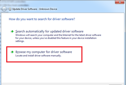
Fig. 9.
Select “x86” driver for 32-bit machine, or x64 for 64-bit machine. If not sure, select root ("vcom") folder (folder in which x64 and x86 lays inside).
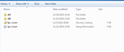
Fig. 10.
IOmod configuration with PuTTY terminal
Configuration of IOmod device is done through CLI (Command Line Interface) on a virtual COM port. Drivers needed for MS Windows to install VCOM will be provided. To open up CLI simply connect to specific V-COM port with terminal software (it is advised to use PuTTY terminal software. If other software is being used, user might need to send <return> symbol after each command). When connected user should immediately see main screen. Accidental close of the terminal window does not stop USB connection, user can connect terminal program again, and press any key on keyboard to show up main menu again.
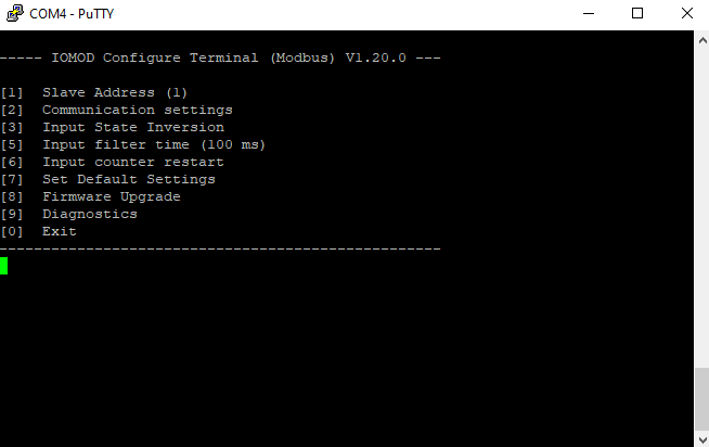
Fig. 11.
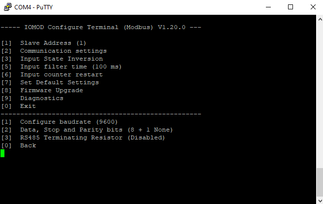
Fig. 12.
Main Menu
|
Menu Name |
Function |
Values |
Default Values |
|
| 1. |
Slave Address |
Modbus Slave address / ID |
1-254 |
1 |
| 2. |
Communication settings |
Enters configuring screen for communication settings. |
- |
- |
| 2.1 |
Configure baudrate |
Configure number of bits transmitted per second |
100 - 256 000 |
9600 |
| 2.2 |
Data, Stop and Parity bits |
Configure length and content of packets |
[1] 8+1 [2] 8+2 Parity: [1] None [2] Odd [3] Even [4] Mark [5] Space |
8+1+N |
| 2.3 |
RS485 Terminating Resistor |
RS485 120 Ohms Terminating Resistor |
[1] Enable [2] Disable |
Disabled |
| 3. |
Input State Inversion |
Input state inversion for individual pins. Inverts states of input signals, so that high input voltage is considered to be logical 0 and vice versa. |
[1] Inverted [2] Set Normal |
Normal |
| 4. |
Input filter time |
Filter for short input pulses |
0 - 256 000 (ms) |
100 |
| 5. |
Input counter restart |
Restarts all input counter registers to 0 |
[1] Confirm [0] Cancel |
- |
| 6. |
Set Default Settings |
Sets Default Settings |
[1] Confirm [0] Cancel |
- |
| 7. |
Firmware Upgrade |
Mass Storage Device Firmware Upgrade |
[1] Confirm [0] Cancel |
- |
| 8. |
Diagnostics |
Input / Output states |
- |
- |
| 0. |
Exit |
Exit and disconnect |
- |
- |
Protocol simulator
When entered diagnostics screen, user can turn on USB protocol simulator mode by pressing [9]. When protocol simulator is turned on, device will communicate through USB port rather than RS-485 line. Communication on RS-485 line is closed and all IEC-101 commands will be accepted only from USB. To exit this mode user must restart device.
Firmware upgrade over USB
To update device firmware user must enter main configuration menu and enter Firmware upgrade screen by pressing [8] is shown in Fig. 13.
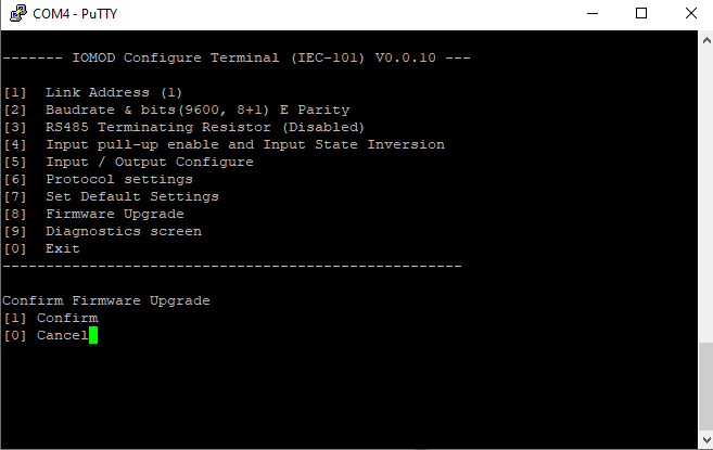
Fig. 17.
Confirm upgrade by pressing [1];
Device should enter a Firmware Upgrade mode. It means that device switches from USB Console mode into Mass storage device and computer recognize it as USB Storage.
Usually after confirming the upgrade a window with an error message appears (Fig. 14)

Fig. 18.
User then must delete existing file “firmware.bin”, and simply drag and drop new firmware file.
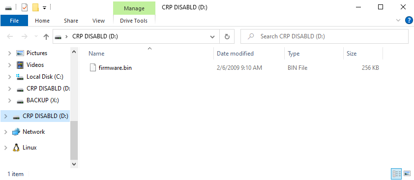
Fig. 19.
Finally, reconnect device and check firmware version. Lastly, you may want to set default settings by pressing [7].
IOMOD 8DI4RO User Manual IEC 60870-5-103
Introduction
IOMod 8DI4RO is a small-size stand-alone Modbus RTU, IEC 60870-5-103 or IEC-60870-5-101 digital input and relay output controller (protocol depends on firmware). IOmod can be used for industrial applications, where digital signaling is used and robust communication is needed. IOmod is an ideal solution for applications such as data acquisition, control, and process monitoring at remote places. This user manual is written for IEC 60870-5-103 protocol firmware version.
Features
-
8 digital inputs;
-
Configurable active input signal polarity or input inversion;
-
4 relay outputs;
-
Galvanically isolated inputs and outputs;
-
Pulsed or latched mode for individual outputs;
-
Possible output feedback measurement with inputs;
-
Configuration over USB console or MODBUS RTU;
-
Values with data and time information;
-
Drag and Drop firmware upgrade over USB mass storage;
-
Modbus RTU, IEC-60870-5-103, IEC-60870-5-101 communication over RS485;
- Software selectable RT 120 Ohm termination resistor on RS485 interface;
-
LED indication for input/output and data transmission;
-
Easy integration with WCC Lite gateway and CloudIndustries.eu platform;
Operational information
IOmod 8DI4RO uses Modbus RTU, IEC 60870-5-103, or IEC 60870-5-101 protocol to communicate with the master device over the RS485 interface. Protocol used by the device can be changed by uploading the corresponding firmware. Default communication settings are:
| Baud rate | 9600 |
| Data bits | 8 |
| Parity | Even |
| Stop bits | 1 |
| Link address | 1 |
IOmod 8DI4RO configuration can be changed over a USB interface with a terminal console like PuTTY or similar.
Status LED
Status LED can be in 2 colors :
Blue - Device connected to USB.
Green - Normal operation.
Rx/Tx LED
The RX/TX LED on the IOMod flashes when data is either being transmitted or received via the RS485 port.
IEC 60870-5-103 working information
Initialization
IOmod uses a standard IEC-60870-5-103 communication scheme. Initiation, control messages and queries are initiated by the master (controlling station), while IOmod device (controlled station) only answers these requests.
Therefore, the first message should be sent by master to start/restart communication (function code 7) (RESET CU or LINK RESET FCB). This message is answered by IOmod with an acknowledgement (ACK) (0). After that master sends RequestStatusOfLink (9) message. The message is answered by slave with Status (11) message. Finally, master sends ResetOfRemoteLink (0) message which has to be answered with ACK (0) message from slave.
The initialization procedure enables master to proceed with sending other messages defined by IEC- 60870-5-103 protocol. Other messages are ignored until a successful initialization has taken place.
Data polling
When initialization is complete, master may poll IOmod device with both Class 1 and Class 2 requests. Class 2 is used when master polls for a cyclic data. Controlled device answers with a message containing Access Demand flag when spontaneous data exists and master then sends request for Class 1. IOmod would then respond with time-tagged message.
On first Class 1 request IOmod device always asks for the Access Demand to send an identification string. However, if there are spontaneous messages to be sent, they will be sent before the identification string.
Output control
To enable or disable relay outputs master (controlling station) sends commands conforming to the IEC-60870-5-103 protocols. The function type of the output commands has to be 128 (80h). Info number represents the number of output pin (1-4 accordingly). Info elements shows DPI information of output state (0 – intermediate, 1 – off, 2 – on and 3 – not used (defines error)). Successful command is accepted with a positive acknowledge.
Input messages
When input status changes, IOmod device filters input glitches through filters with a user configurable filter time. When the filter is passed device sends “Spontaneous” message with “Information number” fields displaying input pin addresses and default "Function type" of 160 (A0h). Please note that spontaneous messages are answered with a four-byte time structure not containing date info. Controlling station should therefore be able to handle the signals sent before the start of a new day.
Time synchronization
To initiate the time synchronization between devices master must send variable frame, with Function Type = 0 (GLB), Type Identification = 6, Information Number = 0 and Cause of Transmission = 8. Info elements must contain the 7 byte time structure.
As per IEC-60870-5-103 protocol specification time synchronization can be completed for multiple devices using broadcasting messages. It is included in IEC-60870-5-103 firmware since version 1.7.3. To broadcast time synchronization message, link address should be equal to 255.
General interrogation
General Interrogation (GI) is initiated by the master with variable frame, including Function Code = 3 (User data with ACK), Type Identification = 7, Information number = 0 and Cause of Transmission = 9. Slave device then responds with an acknowledgement (ACK). Master gets IOMod data by polling with Class 2 requests. IOmod device responds with a time-tagged message, including DPI states of inputs and outputs (Outputs are sent first). Output and input pin numbers are represented by “Info number” fields in received packets from IOMod. Finally, slave transmits “End of GI” (Cause of Transmission = 10, Type Identification = 8).
Device configuration
Input inversion and polarity selection
Unlike 8DI8DO IOmod 8DI4RO does not have pull-up resistors. If user desires to turn input status on, when that input signal is low, user then inverts inputs logically. All input indication LED’s stay the same (are not inverted).
Input / Output grouping
Sometimes two inputs or two outputs must be captured as one DPI input or output. Inputs and outputs can be grouped into the pairs of two. This allows outputs to be controlled by one DPI command (of address of first output in the group). Only two neighbor pins can be grouped into pair, while first pin in pair must be an odd number pin. When grouped, second pin in the pair is not used anymore – all requests for this pin generate an error. For example – RO1.1-2 and RO2.1-2 can be grouped, after that RO2.1-2 is not used; RO2.1-2 and RO3.1-2 cannot be grouped; RO3.1-2 and RO4.1-2 can be grouped, but RO4.1-2 is not used then, etc.
Fig. 1. picture shows outputs and inputs ungrouped and controlled independently. In this mode, General Interrogation will be composed of 4 output states and 8 input states.
Fig. 1.
Let's consider a situation shown in Fig. 2. In the picture below first two relay outputs are grouped into pair. Also 3rd and 4th inputs are grouped into pair. Now, General interrogation will be composed of 3 output states (with RO2.1-2 missing), and 7 input states (with IN4 missing). Output and input numbers is represented by “Info number” in protocol.
Fig. 2.
Input filter
Input filter is a simple glitch filter with time input. This filter time corresponds to stable time that input must achieve before sending a status change.
Output pulse time
User can configure outputs to be pulse controlled – it means that output will be turned on for configured amount of time. When this time runs out, output is turned off. This is useful when pulse toggle relays are used. Output pulse is independent from output grouping option and can be used on both grouped and ungrouped outputs. When output is grouped, device will allow only one command completion at a time – when output is already turned ON, other “turn ON” requests will be responded with NACK. If user desires latching outputs to be used, output pulse time is set to 0.
In the picture below is depicted an example of pulse output usage. Inputs and outputs are grouped, and output pulse time is set to 1s. When user sends ON command, RO2.1-2 are pulsed for 1s, and relay is set. This will connect NO contact and IN2 will turn on (assuming it is not inverted). When user sends OFF command, RO1.1-2 are pulsed, and relay is reset, turning IN1 on.
Output detection with inputs
Users can detect an output change with inputs.
Fig. 4.
To find out if relays are turned on, user can connect relay outputs to IOmod inputs (maximum allowed voltage must be taken into account).
Technical information
|
|
System |
|
|
1. |
Dimensions |
101 x 119 x 22.5 mm |
| 2. |
Case |
IP20, blend PC/ABS self-extinguishing, black |
|
3. |
Working environment |
Indoors |
|
4. |
Operating temperature |
from -30°C to +70°C |
|
5. |
Humidity |
5-95% RH (non-condensing) |
|
6. |
Configuration |
USB – serial console, MODBUS RTU |
|
7. |
Firmware upgrade |
USB – mass storage device |
|
|
Electrical specifications |
|
|
|
Inputs |
|
|
8. |
Nominal input voltage range |
12-48VDC |
|
9. |
Isolation |
8 X 3kV(rms) |
|
10. |
Maximum input voltage |
60VDC |
|
|
Output relay contacts ratings |
|
|
11. |
Isolation |
4 X 3kV(rms) |
|
12. |
Rated resistive load |
5 A (at 250 VAC or at 30 VDC) |
|
13. |
Rated inductive (L/R=7ms) load |
2 A (at 250 VAC or at 30 VDC) |
|
14. |
Maximum switching voltage |
277 VAC 125 VDC |
|
15. |
Maximum switching current |
5 A |
|
|
Power |
|
|
16. |
Power Supply |
12-24 VDC / 9-33 VDC (full range) |
|
17. |
Current consumption |
70 mA |
In the Fig. 5. you can see internal structure of 8DI4RO IOmod. An important fact to metion is that as it can be noticed in the scheme below all inputs are isolated. However ground connection is common for all phototransistors.
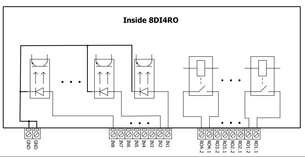
Fig. 5.
Mounting and installation guide
IOmod 8DI4RO RS485 interface
IOmod 8DI4RO has an integrated 120Ω termination resistor which can be enabled or disabled over USB configuration. It is recommended to use termination at each end of the RS485 cable. See typical connection diagram on Fig. 6.
Fig. 6.
IOmod 8DI4RO has 1/8 Unit load receiver which allows to have up to 256 units on line (compared to standard 32 units). To reduce reflections, keep the stubs (cable distance from main RS485 bus line) as short as possible when connecting device.
IOmod 8DI4RO inputs
Typical application of IOmod 8DI4RO inputs is shown on Fig. 2. When default configuration for inputs is applied, user will see inputs connected to +12-24V as “high” or state “1” and input status LED will glow.
Fig. 7.
User also can configure to enable software input inversion. With this configuration, user will see inputs connected to 0V (see Fig. 3.) as “high” or state “1”, input status LED will NOT glow.
IOmod 8DI4RO outputs
IOmod 8DI4RO has 4 relay outputs. Internal clamp diodes are connected to each output which makes IOmod 8DI4RO ideal for driving inductive loads like relays. Maximum 10A per output is allowed. For higher loads outputs can be connected in parallel. Make sure your power supply can provide enough power. Typical application of outputs is shown on Fig. 4.
Fig. 8.
Configuration over USB
Driver installation
Device requires USB drivers to work as a Virtual COM port. First-time connection between device and computer could result in “Device driver software was not successfully installed” error (Fig. 5.).
Fig. 10.
Drivers can be installed from Wiki Esleseta -> Downloads -> IOMOD Series Downloads-> Firmware and tools -> IOMOD USB drives for Windows;
User then manually installs drivers by selecting downloaded driver folder:
Go to Control Panel -> Hardware and Sound -> Device Manager
Select failed device;
Press “Update driver software”; screen in Fig. 6. should appear:
Fig. 11.
Select “x86” driver for 32-bit machine, or x64 for 64-bit machine. If not sure, select root ("vcom") folder (folder in which x64 and x86 lays inside).
Fig. 12.
IOmod configuration with PuTTY terminal
Configuration of IOmod device is done through CLI (Command Line Interface) on a virtual COM port. Drivers needed for MS Windows to install VCOM will be provided. To open up CLI simply connect to specific V-COM port with terminal software (it is advised to use PuTTY terminal software. If other software is being used, user might need to send <return> symbol after each command). When connected user should immediately see main screen. Accidental close of the terminal window doesn’t stop USB connection, user can connect terminal program again, and press any key on keyboard to show up main menu again.
IOMOD 8DI4RO User Manual IEC 60870-5-101
Introduction
IOMod 8DI4RO is a small-size stand-alone Modbus RTU, IEC 60870-5-103 or IEC-60870-5-101 digital input and relay output controller (protocol depends on firmware). IOmod can be used for industrial applications, where digital signaling is used and robust communication is needed. IOmod is an ideal solution for applications such as data acquisition, control, and process monitoring at remote places. This user manual is written for IEC 60870-5-101 protocol firmware version.
Features
-
8 digital inputs;
-
Configurable active input signal polarity or input inversion;
-
4 relay outputs;
-
Galvanically isolated inputs and outputs;
-
Pulsed or latched mode for individual outputs;
-
Configuration over USB console or MODBUS RTU;
-
Values with data and time information;
-
Drag and Drop firmware upgrade over USB mass storage;
-
Modbus RTU, IEC-60870-5-103, IEC-60870-5-101 communication over RS485;
- Software selectable RT 120 Ohm termination resistor on RS485 interface;
-
LED indication for input/output and data transmission;
-
Easy integration with WCC Lite gateway and CloudIndustries.eu platform;
Operational information
IOmod 8DI4RO uses Modbus RTU, IEC 60870-5-103, or IEC 60870-5-101 protocol to communicate with the master device over the RS485 interface. Protocol used by the device can be changed by uploading the corresponding firmware. Default communication settings are 9600 baud rate, 8E1, Link address – 1.
IOmod 8DI4RO configuration can be changed over a USB interface with a terminal console like PuTTY or similar.
Status LED
Status LED can be in 2 colors :
Blue - Device connected to USB.
Green - Normal operation.
Rx/Tx LED
The RX/TX LED on the IOMod flashes when data is either being transmitted or received via the RS485 port.
IEC 60870-5-101 working information
Initialization
IOmod uses a standard IEC-60870-5-101 communication scheme. Initiation, control messages, and queries are initiated by the master (controlling station), while the IOmod device (controlled station) only answers these requests. Therefore, the first message should be sent by the master to request status of link (function code = 9). This message is answered by IOmod with the status of link (function code = 11) if link is available. Otherwise there is going to be no response. After receiving the status of link the master will send Reset of remote link command (function code = 0) to restart the communication. The IOMod can respond with either acknowledgment (function code = 0, ACK) or Negative Acknowledgment (function code = 1, NACK). If IOMod respond is ACK then the initialization procedure is finished. The described procedure enables the master to proceed with sending other messages defined by the IEC-60870-5-101 protocol.
Data polling
When initialization is complete, the master may request data from the IOmod device with general interrogation. Although according to the protocol specification IOMod will send data on value change. The 8DI4RO IOMod responds with data type 1 (M_SP_NA_1) a single-point information.
Output control
To control device outputs master (controlling station) sends a command conforming to the IEC-60870-5-101 protocols. The IOAs for outputs are 101 (RO1), 102 (RO2), 103 (RO3) and 104 (RO4). By sending the 45-type command (C_SC_NA_1, single point command) with the selected IOA you can either turn ON or OFF outputs. Negative acknowledgement is returned if the sent command is not configured. For example wrong IOA address or Data Type.
Inputs
The IOAs for the inputs are: 9 (DI1), 10 (DI2), 11 (DI3), 12 (DI4), 13 (DI5), 14 (DI6), 15 (DI7) and 16 (DI8).
Time synchronization
To initiate the time synchronization between devices the master must send a Clock Sync command. The command type is C_CS_NA_1 (103) and the Cause of Transmission (COT) has to be 6. The command has to be sent to the correct link address and CASDU, which is the same as the link address by default. If the sent frame is correct the IOMod will respond with a C_CS_NA_1 (103) type command with the COT (cause of transmission) of 0x07 and the p/n bit will be set to 0 (positive confirmation). Also the command will be time-tagged with the device time. If the time synchronization feature is disabled or the command is sent to an undefined CASDU the response is the same except the p/n bit will be set to 1 (negative confirmation) and the COT byte will be equal to 0x47.
General interrogation
General Interrogation (GI) is initiated by the master sending the General Interrogation command. The command type is C_IC_NA_1 (100) and the Cause of Transmission (COT) has to be 6. The command has to be sent to the correct link address and CASDU, which is the same as the link address by default. If the sent frame is correct the IOMod will respond with a C_IC_NA_1 (100) type command with the COT (cause of transmission) of 0x07 and the p/n bit will be set to 0 (positive confirmation). Otherwise, it will respond with the same command just that the p/n bit will be set to 1 (negative confirmation) and the COT byte will be equal to 0x47. Then the device will begin to send all of its data. If the GI was successful the IOMOD will also send another 100 type command with the COT (cause of transmission) of 10 (ActTerm) meaning the general interrogation is over.
Device configuration
Input inversion and polarity selection
Unlike 8DI8DO IOmod 8DI4RO does not have pull-up resistors. If user desires to turn input status on, when that input signal is low, user then inverts inputs logically. All input indication LED’s stay the same (are not inverted).
Input / Output grouping
Sometimes two inputs or two outputs must be captured as one DPI input or output. Inputs and outputs can be grouped into the pairs of two. This allows outputs to be controlled by one DPI command (of address of first output in the group). Only two neighbor pins can be grouped into pair, while first pin in pair must be an odd number pin. When grouped, second pin in the pair is not used anymore – all requests for this pin generate an error. For example – RO1.1-2 and RO2.1-2 can be grouped, after that RO2.1-2 is not used; RO2.1-2 and RO3.1-2 cannot be grouped; RO3.1-2 and RO4.1-2 can be grouped, but RO4.1-2 is not used then, etc.
Fig. 1. picture shows outputs and inputs ungrouped and controlled independently. In this mode, General Interrogation will be composed of 4 output states and 8 input states.
Fig. 1.
Let's consider a situation shown in Fig. 2. In the picture below first two relay outputs are grouped into pair. Also 3rd and 4th inputs are grouped into pair. Now, General interrogation will be composed of 3 output states (with RO2.1-2 missing), and 7 input states (with IN4 missing). Output and input numbers is represented by “Info number” in protocol.
Fig. 2.
Input filter
Input filter is a simple glitch filter with time input. This filter time corresponds to stable time that input must achieve before sending a status change.
Output pulse time
User can configure outputs to be pulse controlled – it means that output will be turned on for configured amount of time. When this time runs out, output is turned off. This is useful when pulse toggle relays are used. Output pulse is independent from output grouping option and can be used on both grouped and ungrouped outputs. When output is grouped, device will allow only one command completion at a time – when output is already turned ON, other “turn ON” requests will be responded with NACK. If user desires latching outputs to be used, output pulse time is set to 0.
In the picture below is depicted an example of pulse output usage. Inputs and outputs are grouped, and output pulse time is set to 1s. When user sends ON command, RO2.1-2 are pulsed for 1s, and relay is set. This will connect NO contact and IN2 will turn on (assuming it is not inverted). When user sends OFF command, RO1.1-2 are pulsed, and relay is reset, turning IN1 on.
Output detection with inputs
Users can detect an output change with inputs.
Fig. 3.
To find out if relays are turned on, user can connect relay outputs to IOmod inputs (maximum allowed voltage must be taken into account). When relays are turned on, device responds with IEC-60870-5-101 protocol message “Remote Operation”. If inputs are never turned on or off, device will send “Remote Operation” message after time-out period, with current input statuses. Time-out period is configured by user as a Feedback Time.
Technical information
|
|
System |
|
|
1. |
Dimensions |
101 x 119 x 22.5 mm |
| 2. |
Case |
IP20, blend PC/ABS self-extinguishing, black |
|
3. |
Working environment |
Indoors |
|
4. |
Operating temperature |
from -30°C to +70°C |
|
5. |
Humidity |
5-95% RH (non-condensing) |
|
6. |
Configuration |
USB – serial console, MODBUS RTU |
|
7. |
Firmware upgrade |
USB – mass storage device |
|
|
Electrical specifications |
|
|
|
Inputs |
|
|
8. |
Nominal input voltage range |
12-48VDC |
|
9. |
Isolation |
8 X 3kV(rms) |
|
10. |
Maximum input voltage |
60VDC |
|
|
Output relay contacts ratings |
|
|
11. |
Isolation |
4 X 3kV(rms) |
|
12. |
Rated resistive load |
5 A (at 250 VAC or at 30 VDC) |
|
13. |
Rated inductive (L/R=7ms) load |
2 A (at 250 VAC or at 30 VDC) |
|
14. |
Maximum switching voltage |
277 VAC 125 VDC |
|
15. |
Maximum switching current |
5 A |
|
|
Power |
|
|
16. |
Power Supply |
12-24 VDC / 9-33 VDC (full range) |
|
17. |
Current consumption |
70 mA |
In the Fig. 5. you can see internal structure of 8DI4RO IOmod. An important fact to metion is that as it can be noticed in the scheme below all inputs are isolated. However ground connection is common for all phototransistors.
Fig. 4.
Mounting and installation guide
IOmod 8DI4RO RS485 interface
IOmod 8DI4RO has an integrated 120Ω termination resistor which can be enabled or disabled over USB configuration. It is recommended to use termination at each end of the RS485 cable. See typical connection diagram on Fig. 6.
Fig. 5.
IOmod 8DI4RO has 1/8 Unit load receiver which allows to have up to 256 units on line (compared to standard 32 units). To reduce reflections, keep the stubs (cable distance from main RS485 bus line) as short as possible when connecting device.
IOmod 8DI4RO inputs
Typical application of IOmod 8DI4RO inputs is shown on Fig. 2. When default configuration for inputs is applied, user will see inputs connected to +12-24V as “high” or state “1” and input status LED will glow.
Fig. 6.
User also can configure to enable software input inversion. With this configuration, user will see inputs connected to 0V (see Fig. 3.) as “high” or state “1”, input status LED will NOT glow.
IOmod 8DI4RO outputs
IOmod 8DI4RO has 4 relay outputs. Internal clamp diodes are connected to each output which makes IOmod 8DI4RO ideal for driving inductive loads like relays. Maximum 10A per output is allowed. For higher loads outputs can be connected in parallel. Make sure your power supply can provide enough power. Typical application of outputs is shown on Fig. 4.
Fig. 7.
Configuration over USB
Driver installation
Device requires USB drivers to work as a Virtual COM port. First-time connection between device and computer could result in “Device driver software was not successfully installed” error (Fig. 5.).
Fig. 8.
Drivers can be installed from Wiki Esleseta -> Downloads -> IOMOD Series Downloads-> Firmware and tools -> IOMOD USB drives for Windows;
User then manually installs drivers by selecting downloaded driver folder:
Go to Control Panel -> Hardware and Sound -> Device Manager
Select failed device;
Press “Update driver software”; screen in Fig. 6. should appear:
Fig. 9.
Select “x86” driver for 32-bit machine, or x64 for 64-bit machine. If not sure, select root ("vcom") folder (folder in which x64 and x86 lays inside).
Fig. 10.
IOmod configuration with PuTTY terminal
Configuration of IOmod device is done through CLI (Command Line Interface) on a virtual COM port. Drivers needed for MS Windows to install VCOM will be provided. To open up CLI simply connect to specific V-COM port with terminal software (it is advised to use PuTTY terminal software. If other software is being used, user might need to send <return> symbol after each command). When connected user should immediately see main screen. Accidental close of the terminal window doesn’t stop USB connection, user can connect terminal program again, and press any key on keyboard to show up main menu again.
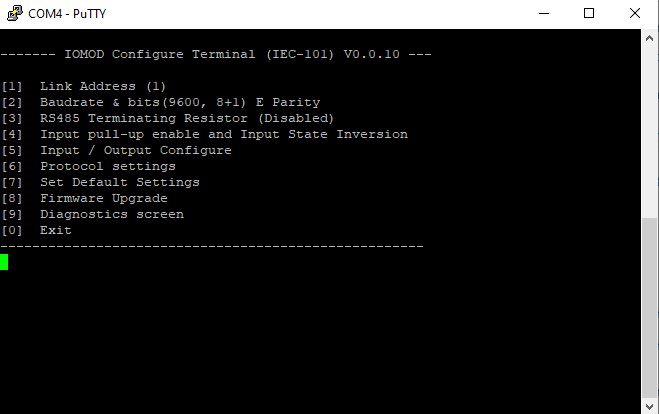
Fig. 11.
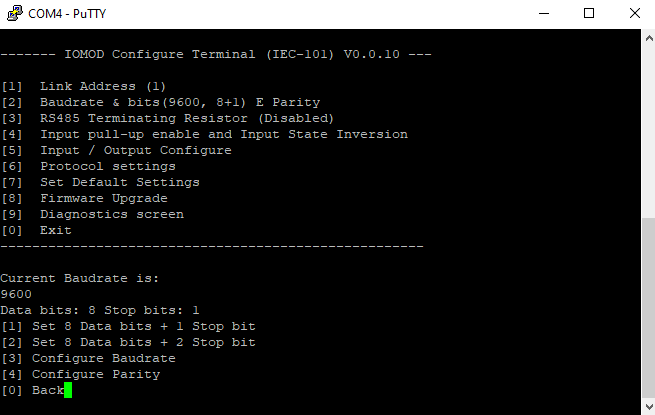
Fig. 12.
A lot of options can be changed after entering Input / Output configure screen (Fig. 9.). These include filter time, output pulse time, input and output configuration, output detection with inputs screens.

Fig. 13.
Input (Fig. 10.) and output grouping screen show the connection between neighbor pins. Vertical bars show that input or outputs are not grouped.

Fig. 14.
A connection between a grouped pair of inputs or outputs is depicted by a slash and a backslash that connects beneath the pair (Fig. 11.).
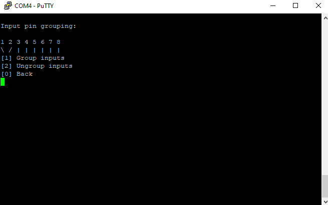
Fig. 15.
Changes in the device and firmware version are shown in a Diagnostics Screen. Such diagnostics screen for IOmod 8DI4RO is shown in Fig. 12.
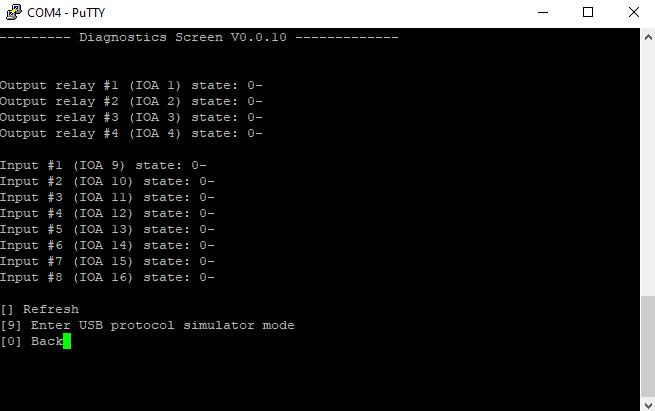
Fig. 16.
Main Menu
|
|
Menu name |
Function |
Values |
Default values |
|
|
1. |
Link Address |
Setts Link address |
1-255 |
1 |
|
|
2. |
Baudrate & bits(9600, 8+1) E Parity |
Enters configuring screen for communication settings |
8+1 or 8+2 (Data + Stop), None, Odd, Even, Mark, Space (Parity) |
9600, 8+1, Parity -Even |
|
|
3. |
RS485 Terminating Resistor |
RS485 120 Ohms Terminating Resistor |
1 – 2 (Enable/Disable) |
Disabled |
|
|
4. |
Input pull-up enable and Input State Inversion |
Enables input pull-up resistor. Inputs then activated by low signal; Input inversion (Inverts input states in protocol logic) |
1 – 2 (Enable/Disable) |
Both disabled |
|
|
5. |
Input / Output configure |
Enters screen for configuring (see 6.1 – 6.5 rows below) |
- |
- |
|
|
5.1 |
Input grouping; |
Groups or ungroups inputs |
8 inputs ungrouped / 4 pairs grouped |
All inputs ungrouped by default |
|
|
5.2 |
Output grouping; |
Groups or ungroups outputs |
8 outputs ungrouped / 4 pairs grouped |
All outputs ungrouped by default |
|
|
5.3 |
Input filter time; |
Input glitch filter – minimum stable time to detect input |
1 – 60000 milliseconds |
100 |
|
|
5.4 |
Output pulse time and select timeout; |
Sets short and long pulse time and selects timeout for individual outputs. |
0 – 60000 milliseconds (0 if not used) |
0 |
|
| 6. | Protocol settings; |
Sets the time mode for info objects, IOA size and enables or disables the use of command qualifier for output pulses. |
- |
- |
|
| 6.1 | Toggle 24/56 bit time |
Changes toggle bit time either to 24 or to 56 |
24/56 |
56 |
|
| 6.2 | Change IOA size |
Changes IOA size |
1-3 |
1 |
|
| 6.3 | Toggle use of command qualifier |
Enables or disables toggle use of command qualifier |
Disabled/Enabled |
Enabled |
|
|
7. |
Set default settings; |
Sets Default Settings |
(1 to confirm, 0 to cancel) |
- |
|
|
8. |
Firmware update; |
Mass Storage Device Firmware Upgrade |
(1 to confirm, 0 to cancel) |
- |
|
|
9. |
Diagnostics screen; |
Input / Output states |
- |
- |
|
|
0. |
Exit; |
Exit and disconnect |
- |
- |
|
Protocol simulator
When entered diagnostics screen, user can turn on USB protocol simulator mode by pressing [9]. When protocol simulator is turned on, device will communicate through USB port rather than RS-485 line. Communication on RS-485 line is closed and all IEC-101 commands will be accepted only from USB. To exit this mode user must restart device.
Firmware upgrade over USB
To update device firmware user must enter main configuration menu and enter Firmware upgrade screen by pressing [8] is shown in Fig. 13.
Fig. 17.
Confirm upgrade by pressing [1];
Device should enter a Firmware Upgrade mode. It means that device switches from USB Console mode into Mass storage device and computer recognize it as USB Storage.
Usually after confirming the upgrade a window with an error message appears (Fig. 14)
Fig. 18.
User then must delete existing file “firmware.bin”, and simply drag and drop new firmware file.
Fig. 19.
Finally, reconnect device and check firmware version. Lastly, you may want to set default settings by pressing [7].
Firmware version 2
IOMOD 8DI4RO User Manual
1. Introduction
IOMod 8DI4RO is a stand-alone digital input and relay output controller. This device is used for industrial applications where digital signaling is used and robust communication is essential. It is controlled over Modbus, IEC 60870-5-101 or IEC 60870-5-103 protocol, and can be connected in parallel with other Modbus, IEC 60870-5-101 or IEC 60870-5-103 equipment in a multi-drop installation scheme as in any SCADA system.
1.1 Features
-
8 digital inputs;
- 4 relay outputs;
-
Pulsed or latched mode for individual outputs;
-
Possible output feedback measurement with inputs;
-
Galvanically isolated inputs and outputs for enhanced safety and reliability;
-
Firmware upgrade over USB, RS485;
-
Configurable using the IOMod Utility app for user-friendly setup;
-
RS485 interface with a switchable terminating resistor;
- Communication over Modbus RTU, IEC 60870-5-101 and IEC 60870-5-103 protocols;
- Compact case with a removable transparent front panel;
- DIN rail mounting for seamless integration into industrial systems.
1.2 Block diagram
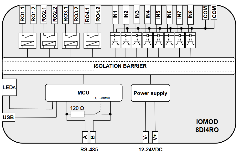
Fig. 1.2.1 IOMOD 8DI4RO internal structure and block diagram
2. Hardware data
2.1 Mechanical drawings
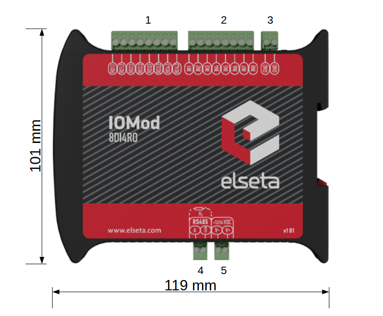
Fig. 2.1.1 IOMod 8DI4RO side view with dimensions and terminals description. 1 - four relay outputs; 2 - eight digital inputs; 3 - ground input; 4 - RS485 interface; 5 - power supply input
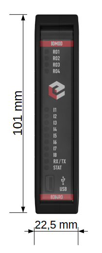
Fig. 2.1.2 IOMod 8DI4RO front view
2.2 Terminal connections
IOMod 8DI4RO has 22 terminals, which are depicted below:
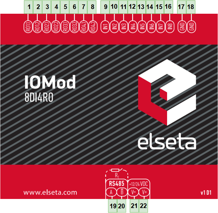
Fig. 2.2.1 IOMod 8DI4RO terminal diagram
The description of each terminal can be found in the table below:
Table 2.2.1 Terminal Specifications
|
Terminal number |
Terminal name |
Description |
|---|---|---|
|
1 |
RO1.1 |
Relay 1 contacts (NO) |
|
2 |
RO1.2 | |
|
3 |
RO2.1 |
Relay 2 contacts (NO) |
|
4 |
RO2.2 | |
|
5 |
RO3.1 |
Relay 3 contacts (NO) |
|
6 |
RO3.2 | |
|
7 |
RO4.1 |
Relay 4 contacts (NO) |
|
8 |
RO4.2 | |
|
9 |
IN1 |
Digital inputs |
|
10 |
IN2 | |
|
11 |
IN3 | |
|
12 |
IN4 | |
|
13 |
IN5 | |
|
14 |
IN6 | |
|
15 |
IN7 | |
|
16 |
IN8 | |
|
17 |
COM |
Common |
|
18 |
COM | |
|
19 |
A |
RS485 input |
|
20 |
B̄ | |
|
21 |
V- |
Power source input |
|
22 |
V+ |
2.3 Status indication
IOMod 8DI4RO has fourteen LEDs (Fig. 2.3.1), which indicate the statuses of the 8 digital inputs, 4 relay outputs, communication, and power.
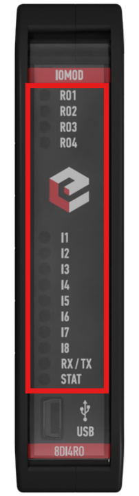
Fig. 2.3.1 IOMod 8DI4RO LEDs physical location
Table 2.3.1 Description of LEDs.
|
Name |
LED color |
Description |
|---|---|---|
|
RO1-RO4 |
🟠 (orange) |
Indicates digital relay output activation |
|
IN1-IN8 |
🟠 (orange) |
Indicates digital input activation |
|
RX/TX |
🟢 (green) |
A blinking green light indicates active communication via the RS485 interface. |
|
STAT |
🟢 (green) |
The power source is connected to the power supply input |
|
🔵 (blue) |
IOMod 8DI4RO is connected to an external device via a USB mini cable |
3. Technical information
Table 3.1 Technical specifications.
| System | ||
| Dimension | 101 x 119 x 22.5 mm | |
| Case | IP20, blend PC/ABS self-extinguishing, black | |
| Working environment | Indoors |
|
| Operating temperature | From -40°C to +85°C | |
| Recommended operating conditions | 5 – 60°C and 20 – 80%RH; | |
| Configuration |
USB, RS485 |
|
| Firmware upgrade | USB, RS485 | |
| Electrical specifications |
||
|
Inputs |
Nominal input voltage range |
9-48VDC |
|
Isolation |
8 X 3kV(rms) |
|
|
Maximum input voltage |
60VDC |
|
|
Outputs |
Isolation |
4 X 3kV(rms) |
| Rated resistive load |
5 A (at 250 VAC or 30 VDC) |
|
| Rated inductive (L/R=7ms) load |
2 A (at 250 VAC or 30 VDC) |
|
| Maximum switching voltage |
277 VAC 125 VDC |
|
| Maximum switching current |
5 A |
|
| Power |
||
| Power Supply | 12-24 VDC / 9-33 VDC (full range) | |
| Current consumption | 120mA @ 12VDC, 60mA @ 24 VDC, 30mA @ 48 VDC | |
4. Mounting and installation
4.1 Connection Diagrams
In this chapter, the various options for connecting the device are discussed.
4.2 Digital inputs
The typical application of IOMod 8DI4RO inputs is shown in (Fig. 4.2.1). When the default input configuration is applied, the user will see inputs connected to +12-24V as “high” or state “1” and the input status LED will glow.
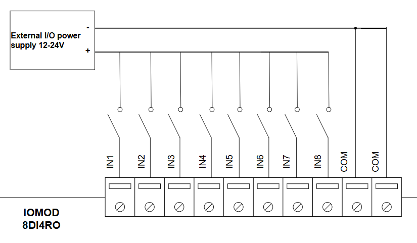
Fig. 4.2.1 IOMod 8DI4RO digital inputs
4.3 Digital relay outputs
IOMod 8DI4RO has 4 relay outputs. Internal clamp diodes are connected to each output, making IOMod 8DI4RO ideal for driving inductive loads like relays. Maximum 5A per output is allowed. The typical application of outputs is shown in (Fig. 4.3.1).
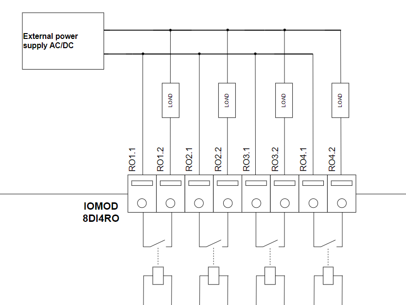
Fig. 4.3.1 IOMod 8DI4RO digital relay outputs
4.4 Power supply
IOMod 8DI4RO needs to be powered by a 9–33 V power source. IOMod 8DI4RO power supply inputs are located next to RS485 interface inputs (Fig 4.4.1).
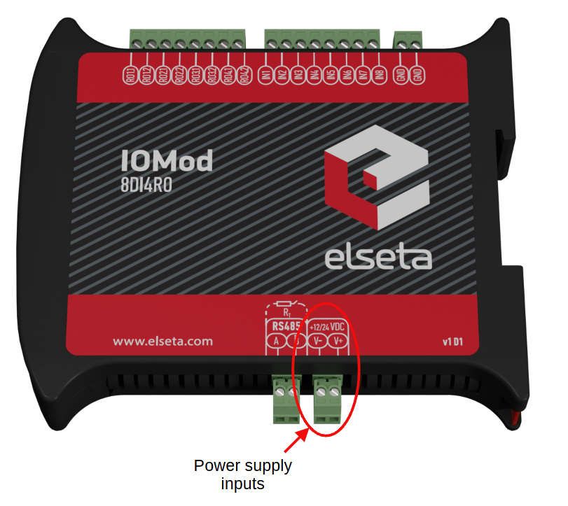
Fig. 4.4.1 Power supply inputs physical location
4.5 USB connection
The IOMod 8DI4RO device features a USB-mini connection port, which primarily facilitates a physical connection between the IOMod and a PC. By selecting the USB interface and the appropriate communication port in the IOMod Utility (Fig. 4.5.1), users can establish a connection to control the device’s parameters. Additionally, this connection can serve as a power source for the module.
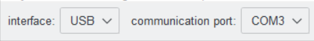
Fig. 4.5.1 IOMod Utility interface and communication port parameters

Fig. 4.5.2 IOMod 8DI4RO USB connection port physical location
5. Parametrization
In this section, the IOMod 8DI4RO settings configuration is described. IOMod 8DI4RO configuration is performed via IOMod Utility (the manual can be accessed here). All IOMod-related settings can be found in the "IOMod settings" tab (Fig. 5.1).

Fig. 5.1 IOMod settings tab
5.1 IOMod settings
To configure IOMod 8DI4RO general settings open the "IOMod settings" tab in IOMod Utility (Fig. 5.1.1).
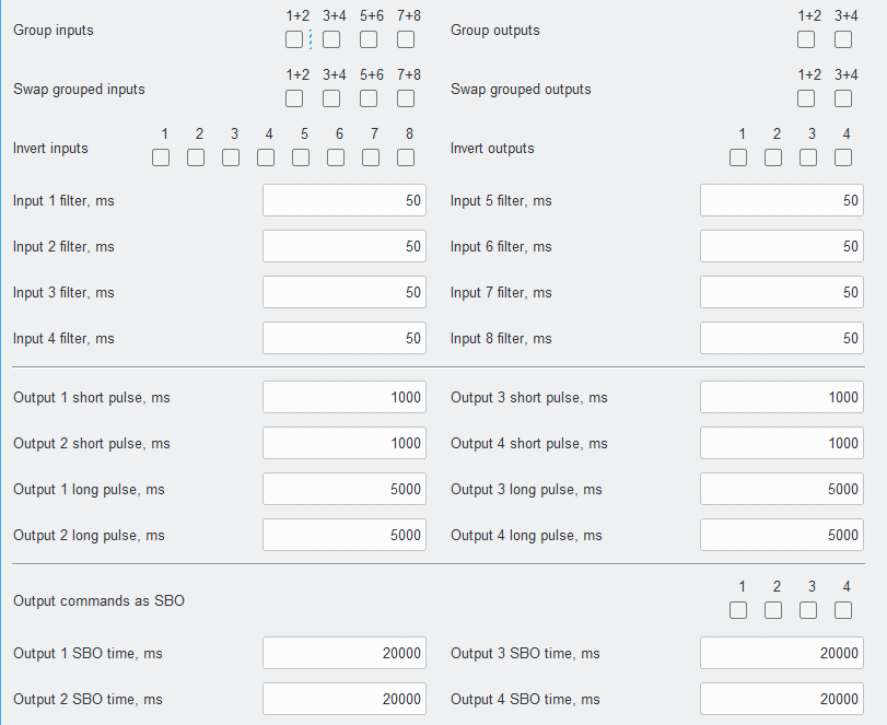
Fig. 5.1.1 IOMod Utility with IOMod 8DI4RO IOMod settings window opened
IOMod Utility is a tool created to configure IOMods with firmware version 2. This tool allows users to connect, configure, and diagnose IOMods such as 8DI8DO, 8DI4RO, 16DI, 8AI, 4RTD, 4CS4VS, METER, and FPI. The Utility's interface allows users to connect to IOMod via USB port or RS485. More information about this tool and its installation can be found on the documentation page IOMod Utility.
To configure IOMod 8DI4RO using IOMod Utility, first connect to a device or create a template as explained in the IOMod Utility documentation. Parameters for IOMod 8DI4RO can be configured on the IOMod settings tab. IOMod with default settings is configured as an Modbus slave device.
Input/Output grouping
Sometimes, two inputs or outputs need to be combined into double point information (DPI). Inputs and outputs can be grouped in pairs of two, where only adjacent pins can be paired, and the first pin in the pair must have an odd number. Once grouped, the second pin in the pair is no longer used, and any requests for it will result in an error. For example, RO1.1-2 and RO2.1-2 can be grouped, but after grouping, RO2.1-2 is disabled. RO2.1-2 and RO3.1-2 cannot be grouped, but RO3.1-2 and RO4.1-2 can be grouped, disabling RO4.1-2.
Input/Output swapping
If desired, input/output groups can be swapped. Grouped Input/Output Swapping allows you to exchange the positions of the grouped pins. After swapping, the even-numbered pin can become the first pin in the pair, and the odd-numbered pin follows. For instance, if RO1.1-2 and RO2.1-2 are grouped, you can swap their positions so that RO2.1-2 becomes the first in the pair. Parameters Group inputs/Group outputs and Swap grouped inputs/Swap grouped outputs are only available for protocols IEC101 and IEC103.
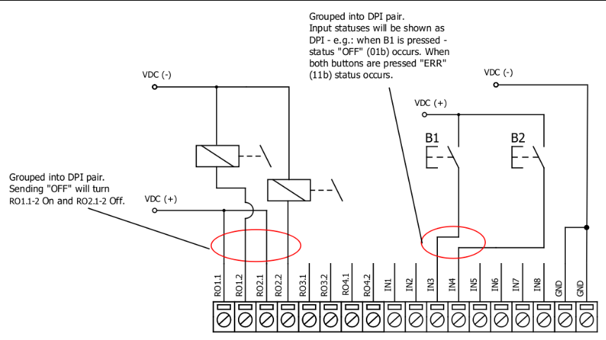
Fig. 5.1.2 Input/Output grouping example
Input/Output grouping and swapping is only available with IEC 60870-5-101 and IEC 60870-5-103 protocols.
Input/Output inversion
Invert inputs and Invert outputs parameters revert the state of the input/output. If the user wants the output status to display as 'ON' when the output signal is in a low state, the outputs can be logically inverted. If the user desires to turn the input status on, when that input signal is low, the user then inverts inputs logically. All input indication LEDs stay the same (are not inverted).
Input filters
Input filters define the time after which the input state is considered changed. The input filter is a simple glitch filter with time input. This filter time corresponds to the stable time that input must achieve before sending a status change. For example, if the input state is OFF and the input filter value is 50 ms, the state changes to ON and stays ON for more than 50 ms, then it will be represented as ON, but if the input state was ON for less than 50 ms it will not change and will stay as OFF. This parameter helps to filter values causing less unneeded data.
Output pulse
Users can configure outputs to be pulse controlled – it means that output will be turned on for the configured amount of time. When this time runs out, output is turned off. This is useful when pulse toggle relays are used. The output pulse is independent of the output grouping option and can be used on both grouped and ungrouped outputs. When output is grouped, the device will allow only one command completion at a time. If the user desires latching outputs to be used, the output pulse time is set to 0.
Unlike the Modbus RTU protocol, the IEC 60870-5-101 protocol offers options for short and long pulses. A short pulse is typically sent with qualifier 1 (QU/QL = 1), while a long pulse is usually sent with qualifier 2 (QU/QL = 2). The IEC 60870-5-103 and Modbus protocols only have pulse parameters without the ability to configure short or long pulses. The default pulse time for Modbus and IEC103 is the same as the short pulse in IEC 60870-5-101 (1000 ms).
Select Before Operate (SBO)
Select Before Operate (SBO) ensures that an output action (such as turning a relay on or off) is carried out only after the output has been explicitly selected. This helps prevent accidental or unauthorized operations, ensuring that the operator's intent is confirmed before acting. For example, the user wants to turn on RO1. First, they issue a select command to RO1. After the selection is acknowledged, the user sends an operation command to turn on RO1. If the command is successful, the IOMod changes the state of the relay, and the output is turned on. If there’s an issue, a negative acknowledgement (NACK) will be sent, and no change will occur. There is also an output SBO time option that ensures that a relay operation is not immediately executed but is instead delayed to allow for confirmation or review before the operation is carried out.
The IOMod settings' available values and ranges can be seen in the table below (Table 5.1.1).
Table 5.1.1 IOMOD 8DI4RO parameter ranges and default values
| Parameter | Range | Default value |
| Input [ ] filter, ms | 1–65535 | 50 |
| Output [ ] short pulse, ms* | 1–65534 | 1000 |
| Output [ ] long pulse, ms* | 1–65534 | 5000 |
| Output [ ] SBO time, ms* | 1–65535 | 20000 |
* The parameters are defined only for the IEC 60870-5-101 communication protocol.
5.2 Device settings for Modbus protocol
IOMod 8DI4RO configuration is performed via IOMod Utility (the manual can be accessed here).
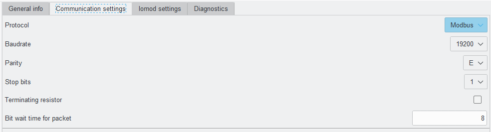 Fig. 5.2.1 Modbus protocol communication settings tab on IOMod utility app
For Modbus protocol users can set: Link address, baudrate, parity, stop bits, terminating resistor, bit wait time (Fig. 5.2.1). See the table below for parameters range and default values (Table 5.2.1).
Table 5.2.1 Communication parameters range and default values
|
Parameter |
Range |
Default values |
|---|---|---|
| Link address | 1-256 | 1 |
| Baudrate | 600, 1200, 2400, 4800, 9600, 19200, 28800, 38400, 57600, 76800, 115200 | 19200 |
| Parity | None, Odd, Even, Mark, Space | Even |
| Stop bits | 1, 2 | 1 |
| Terminating resistor | Enable or disable | disabled |
| Bit wait time for packet | 8-256 | 8 |
5.3 Device settings for IEC 60870-5-101 protocol
For IEC 60870-5-101 protocol users can set: Link address, baudrate, parity, stop bits, terminating resistor and bit wait time, time synchronization timeout, link address size, ASDU size, COT size, and IOA size using the IOMod utility application. See the table below for parameter ranges and default values for IEC 60870-5-101 protocol (Table 5.3.1).
Table 5.3.1 Parameter ranges and default values of IOMod
|
Parameter |
Range |
Default values |
|---|---|---|
|
Link address |
1-65535* |
1 |
| Baudrate | 600, 1200, 2400, 4800, 9600, 19200, 28800, 38400, 57600, 76800, 115200 | 19200 |
| Parity | None, Odd, Even, Mark, Space | Even |
| Stop bits | 1, 2 | 1 |
| Terminating resistor | Enable or disable | Disabled |
| Bit wait time for packet | 8-256 | 8 |
| Time synchronization timeout (s) | 1-65535 | 300 |
| Link address size | 1, 2 | 1 |
| ASDU size | 1, 2 | 1 |
| COT size | 1, 2 | 1 |
| IOA size | 1, 2, 3 | 2 |
* To use Link address value greater than 256, Link address size must be set to "2".
5.4 Device settings for IEC 60870-5-103 protocol
For IEC 60870-5-103 protocol users can set: Link address, baudrate, parity, stop bits, terminating resistor and bit wait time, time synchronization timeout, and input function using the IOMod utility application. See the table below for parameter ranges and default values for IEC 60870-5-103 protocol (Table 5.4.1)
Table 5.4.1 parameter ranges and default values of IOMod
|
Parameter |
Range |
Default values |
|---|---|---|
|
Link address |
1-256 |
1 |
| Baudrate | 600, 1200, 2400, 4800, 9600, 19200, 28800, 38400, 57600, 76800, 115200 | 19200 |
| Parity | None, Odd, Even, Mark, Space | Even |
| Stop bits | 1, 2 | 1 |
| Terminating resistor | Enable or disable | Disabled |
| Bit wait time for packet | 8-256 | 8 |
| Time synchronization timeout (s) | 1-65535 | 300 |
| Input function | 253 | |
| Output command function | 254 | |
| Output status function | 254 |
5.5 Diagnostics
The Utility diagnostics windows allow users to connect to IOMod directly and observe the values in real-time. The 8DI4RO diagnostics window shows input and output states and also allows activation of the outputs. If an input or output is on, the Diagnostics window indicates it with a blue square next to it (unless the input/output is grouped, swapped or inverted, then they would behave in a configured way).
To turn on real-time monitoring of both Diagnostics sections, the "Connect" button to the left of the "Offline" word designation needs to be pressed. After pressing the "Connect" button the word designation of Diagnostics mode changes to "Online", the black circle starts blinking and the button name changes to "Disconnect" (Fig. 5.5.1). When a fault is detected the checkboxes are going to be checked.
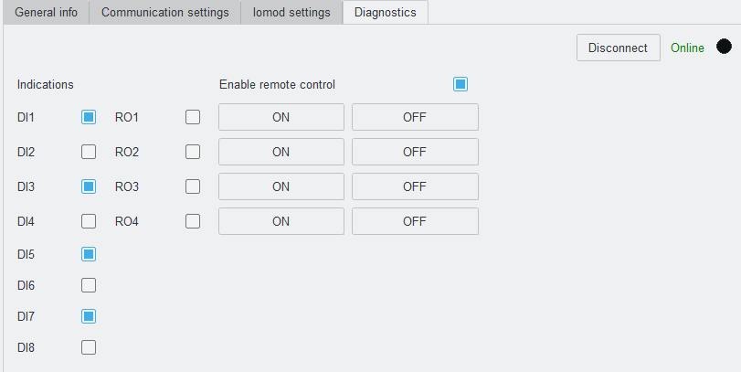
Fig. 5.5.1 IOMOD utility Diagnostics tab in online mode
6. Communication protocols
IOMod 8DI4RO uses Modbus (RTU), IEC 60870-103 or IEC 60870-101 protocols over RS485 connection, which can be used for cable lengths up to 1500 meters and connect up to 30 devices on one line. Default Modbus, IEC 60870-103 and IEC 60870-101 settings are: 19200 bauds/s baudrate, 8E1, Slave (Link) address - 1.
Table 6.1 IOMod 8DI4RO default communication protocol settings
|
Protocol |
baudrate |
parity |
stop bits |
wait byte count |
slave address |
link address size |
ASDU size |
COT size |
IOA size |
Input function |
Output command function |
Output status function |
|---|---|---|---|---|---|---|---|---|---|---|---|---|
|
Modbus |
19200 | Even | 1 | 8 | 1 | |||||||
|
IEC 101 |
19200 | Even | 1 | 8 | 1 | 1 | 1 | 1 | 2 | |||
|
IEC 103 |
19200 | Even | 1 | 8 | 1 | 253 | 254 | 254 | ||||
*Default IOMod 8DI4RO communication protocol is Modbus
6.1 Modbus RTU Operational information
Modbus RTU protocol is a simple and widely used messaging structure for serial communication. In the case of the Modbus protocol IOMod 8DI4RO will send data only after receiving correct queries from a master device. Supported Modbus function codes: FC1, FC2, FC3, FC5, FC6, FC15 and FC16.
01 (0x01) Read Coil status
To read the status of relay outputs (On or Off), Modbus function 01 is used. The IOMod 8DI4RO has 4 relay outputs, with addresses ranging from 0 to 3.
02 (0x02) Read Discrete Inputs
Modbus function 02 reads the status of digital inputs (On or Off). The IOMod 8DI4RO has 8 digital inputs, with addresses ranging from 8 to 15. These inputs are active-high by default.
03 (0x03) Read Holding Registers
Function 03 allow the user to read counter/timer values related to digital inputs. The values in these registers are described in the table below (Table 6.1.1). Two types of values are stored: Pulse Counter and On Timer. The On Timer calculates the duration for which a respective input remains in its active state. It increments every second while the input is active. Pulse counter is incremented by one every time input goes from active state to deactivated state.
05 (0x05) Write single coil
To set the state of a single relay output (On or Off), Modbus function 05 is used. The output addresses range from 0 to 3 (the first output is address 0, last output is address 3).
06 (0x06) Preset Single Register
Function 06 sets the value of a single register. You can set Pulse Counter and On Timer from which value to start incrementing. 0 can be set to reset Pulse Counter and On Timer.
15 (0x15) Preset Multiple coils
Modbus function 15 sets the state of multiple relay outputs (On or Off) simultaneously. The output addresses range from 0 to 3 (the first output is address 0, last output is address 3).
16 (0x16) Preset Multiple Registers
Function 16 sets the values of multiple registers. You can set Pulse Counter and On Timer from which value to start incrementing. 0 can be set to reset Pulse Counter and On Timer.
Table 6.1.1 Modbus protocol register table
| Coil Status FC01 |
|||
| Address (Dec) | Description | Data Type | Access |
| 0 | read the status of relay output 01 | BOOLEAN | R |
| 1 | read the status of relay output 02 | BOOLEAN | R |
| 2 | read the status of relay output 03 | BOOLEAN | R |
| 3 | read the status of relay output 04 | BOOLEAN | R |
| Discrete Inputs FC02 |
|||
| Address (Dec) | Description | Data Type | Access |
|
8 |
Read digital input DI1 |
BOOLEAN |
R |
|
9 |
Read digital input DI2 |
BOOLEAN |
R |
|
10 |
Read digital input DI3 |
BOOLEAN |
R |
|
11 |
Read digital input DI4 |
BOOLEAN |
R |
|
12 |
Read digital input DI5 |
BOOLEAN |
R |
|
13 |
Read digital input DI6 |
BOOLEAN |
R |
|
14 |
Read digital input DI7 |
BOOLEAN |
R |
|
15 |
Read digital input DI8 |
BOOLEAN |
R |
|
Holding Register FC03 |
|||
|---|---|---|---|
|
Address (Dec) |
Description |
Data type |
Access |
|
0 |
input 1 pulse count |
UINT16 |
RW |
|
1-2 |
input 1 on time |
UINT32 |
RW |
|
3 |
input 2 pulse count |
UINT16 |
RW |
|
4-5 |
input 2 on time |
UINT32 |
RW |
|
6 |
input 3 pulse count |
UINT16 |
RW |
|
7-8 |
input 3 on time |
UINT32 |
RW |
|
9 |
input 4 pulse count |
UINT16 |
RW |
|
10-11 |
input 4 on time |
UINT32 |
RW |
|
12 |
input 5 pulse count |
UINT16 |
RW |
|
13-14 |
input 5 on time |
UINT32 |
RW |
|
15 |
input 6 pulse count |
UINT16 |
RW |
|
16-17 |
input 6 on time |
UINT32 |
RW |
|
18 |
input 7 pulse count |
UINT16 |
RW |
|
19-20 |
input 7 on time |
UINT32 |
RW |
|
21 |
input 8 pulse count |
UINT16 |
RW |
|
22-23 |
input 8 on time |
UINT32 |
RW |
|
Force Single Coil FC05 |
|||
|---|---|---|---|
|
Address (Dec) |
Description |
Data type |
Access |
|
0 |
set the state of a single relay output RO1 |
BOOLEAN |
W |
|
1 |
set the state of a single relay output RO2 |
BOOLEAN |
W |
|
2 |
set the state of a single relay output RO3 |
BOOLEAN |
W |
|
3 |
set the state of a single relay output RO4 |
BOOLEAN |
W |
6.2 IEC 60870-5-101 Operational Information
IEC 60870-5-101 (IEC101) is a communication protocol designed for telecontrol applications in power systems, enabling communication between a master station and slave devices (e.g., RTU).
The IOMod 8DI4RO uses the IEC101 protocol to transmit digital input (DI) status and control relay outputs (RO) in a standardized format. Each signal is assigned an Information Object Address (IOA) and a Type Identifier (TI). The protocol efficiently conveys binary status changes (e.g., on/off state of equipment or alarms) and control commands with associated timestamps, enabling reliable communication in automation systems.
Time synchronization is critical for logging events. To synchronize time, the master sends a Time Sync command C_CS_NA_1 (103) with Cause of Transmission (COT) 6. According to the IEC 60870-5-101 protocol specification, time synchronization can be performed for multiple devices using broadcast messages. A master device sends a broadcast timesync command with a broadcast link address. This ensures consistent time-stamping for event recording and fault detection across the network.
Table 6.2.1 IEC 60870-5-101 protocol register table
| IOA | Description | TI |
| 9 | input 1 SPI event | 30 (M_SP_TB_1) |
| 10 | input 2 SPI event | 30 (M_SP_TB_1) |
| 11 | input 3 SPI event | 30 (M_SP_TB_1) |
| 12 | input 4 SPI event | 30 (M_SP_TB_1) |
| 13 | input 5 SPI event | 30 (M_SP_TB_1) |
| 14 | input 6 SPI event | 30 (M_SP_TB_1) |
| 15 | input 7 SPI event | 30 (M_SP_TB_1) |
| 16 | input 8 SPI event | 30 (M_SP_TB_1) |
| 1 | output 1 SPI event | 30 (M_SP_TB_1) |
| 2 | output 2 SPI event | 30 (M_SP_TB_1) |
| 3 | output 3 SPI event | 30 (M_SP_TB_1) |
| 4 | output 4 SPI event | 30 (M_SP_TB_1) |
| 101 | output 1 SPI command | 45 (C_SC_NA_1) |
| 102 | output 2 SPI command | 45 (C_SC_NA_1) |
| 103 | output 3 SPI command | 45 (C_SC_NA_1) |
| 104 | output 4 SPI command | 45 (C_SC_NA_1) |
Table 6.2.2 IEC 60870-5-101 protocol register table for grouped inputs/outputs
| IOA | Description | TI |
| 9 | input 1-2 DPI event | 31 (M_DP_TB_1) |
| 11 | input 3-4 DPI event | 31 (M_DP_TB_1) |
| 13 | input 5-6 DPI event | 31 (M_DP_TB_1) |
| 15 | input 7-8 DPI event | 31 (M_DP_TB_1) |
| 1 | output 1-2 DPI event | 31 (M_DP_TB_1) |
| 3 | output 3-4 DPI event | 31 (M_DP_TB_1) |
| 101 | output 1-2 DPI command | 46 (C_DC_NA_1) |
| 103 | output 3-4 DPI command | 46 (C_DC_NA_1) |
* SPI - single-point information, DPI - double-point information
To read single-point inputs/outputs, TI 30 is used, which provides single-point information with time tag. If double-point inputs/outputs need to be read, TI 31 is used, which provides information with time tag.
TI 45 is used to send a command to a single-point output, whereas TI 46 is used to send a command to a double-point output. If outputs are grouped, to enable or disable relay outputs, the master (controlling station) has to send commands with TI 46 (Table 6.2.2). DPI signals consist of two bits of information, allowing for four possible states:
Table 6.2.2 Double-point states
| Value | State |
| 00 | intermediate |
| 01 | off |
| 10 | on |
| 11 | error |
6.2 IEC 60870-5-103 Operational Information
IEC 60870-5-103 is a communication protocol specifically designed for telecontrol and automation systems in the electrical power industry, particularly for substation automation. IEC 60870-5-103 is more specialized for applications related to protection, control, and monitoring in electrical substations.
Time synchronization is critical for logging events. To synchronize time, the master sends a Time Sync command with function 0 and Cause of Transmission (COT) 8. According to the IEC 60870-5-103 protocol specification, time synchronization can be performed for multiple devices using broadcast messages. For broadcast time synchronization, the master device sends a periodic signal with a time stamp to synchronize the system time of slave devices. If synchronization fails, devices default to their local system time until they successfully resynchronize.
Table 6.3.1 IEC 60870-5-103 protocol register table
| Type |
Function |
INF |
Description |
| 1 (M_TTM_TA_3) |
253 |
1 |
input 1 event |
| 1 (M_TTM_TA_3) |
253 |
2 |
input 2 event |
| 1 (M_TTM_TA_3) |
253 |
3 |
input 3 event |
| 1 (M_TTM_TA_3) |
253 |
4 |
input 4 event |
| 1 (M_TTM_TA_3) |
253 |
5 |
input 5 event |
| 1 (M_TTM_TA_3) |
253 |
6 |
input 6 event |
| 1 (M_TTM_TA_3) |
253 |
7 |
input 7 event |
| 1 (M_TTM_TA_3) |
253 |
8 |
input 8 event |
| 1 (M_TTM_TA_3) |
254 |
1 |
output 1 event |
| 1 (M_TTM_TA_3) |
254 |
2 |
output 2 event |
| 1 (M_TTM_TA_3) |
254 |
3 |
output 3 event |
| 1 (M_TTM_TA_3) |
254 |
4 |
output 4 event |
| 1 (M_TTM_TA_3) |
254 |
1 |
output 1 command |
| 1 (M_TTM_TA_3) |
254 |
2 |
output 2 command |
| 1 (M_TTM_TA_3) |
254 |
3 |
output 3 command |
| 1 (M_TTM_TA_3) |
254 |
4 |
output 4 command |
Table 6.3.2 IEC 60870-5-103 protocol register table for grouped inputs/outputs
| Type | Function | INF | Description |
| 1 (M_TTM_TA_3) | 253 | 1 | input 1-2 event |
| 1 (M_TTM_TA_3) | 253 | 3 | input 3-4 event |
| 1 (M_TTM_TA_3) | 253 | 5 | input 5-6 event |
| 1 (M_TTM_TA_3) | 253 | 7 | input 7-8 event |
| 1 (M_TTM_TA_3) | 254 | 1 | output 1-2 event |
| 1 (M_TTM_TA_3) | 254 | 3 | output 3-4 event |
| 1 (M_TTM_TA_3) | 254 | 1 | output 1-2 command |
| 1 (M_TTM_TA_3) | 254 | 3 | output 3-4 command |
Function 253 is responsible for input event detection. IOMod continuously monitors its input channels to detect changes. Function 254 is responsible for output event detection and command sending. These two functions are default in IOMod utility app (Fig. 6.3.1) but can be modified according to needs.
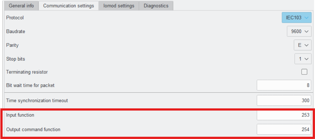
Fig. 6.3.1 IOMod utility input/output functions location
If outputs are grouped, to enable or disable relay outputs, the master (controlling station) has to send commands with function type 254 (Table 6.3.1). DPI signals consist of two bits of information, allowing for four possible states:
Table 6.3.3 Double-point states
| Value | State |
| 00 | intermediate |
| 01 | off |
| 10 | on |
| 11 | error |