# Firmware version 2
# IOMOD 8DI4RO User Manual
### 1. Introduction
IOMod 8DI4RO is a stand-alone digital input and relay output controller. This device is used for industrial applications where digital signaling is used and robust communication is essential. It is controlled over **Modbus, IEC 60870-5-101 or IEC 60870-5-103** protocol, and can be connected in parallel with other Modbus, IEC 60870-5-101 or IEC 60870-5-103 equipment in a multi-drop installation scheme as in any SCADA system.
#### 1.1 Features
- 8 digital inputs;
- 4 relay outputs;
- Pulsed or latched mode for individual outputs;
- Possible output feedback measurement with inputs;
- Galvanically isolated inputs and outputs for enhanced safety and reliability;
- Firmware upgrade over USB, RS485;
- Configurable using the IOMod Utility app for user-friendly setup;
- RS485 interface with a switchable terminating resistor;
- Communication over Modbus RTU, IEC 60870-5-101 and IEC 60870-5-103 protocols;
- Compact case with a removable transparent front panel;
- DIN rail mounting for seamless integration into industrial systems.
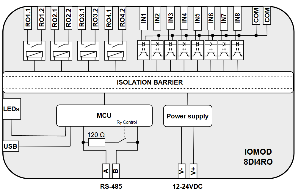
#### 1.2 Block diagram
[](https://wiki.elseta.com/uploads/images/gallery/2025-03/image-1742468999039.png)
Fig. 1.2.1 IOMOD 8DI4RO internal structure and block diagram
### 2. Hardware data
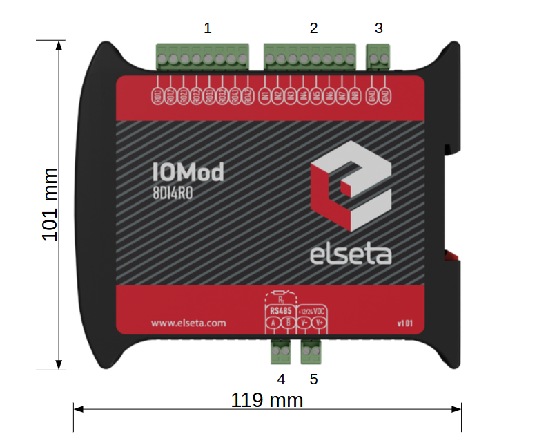
#### 2.1 Mechanical drawings
[](https://wiki.elseta.com/uploads/images/gallery/2025-01/image-1737710083274.png)
Fig. 2.1.1 IOMod 8DI4RO side view with dimensions and terminals description. 1 - four relay outputs; 2 - eight digital inputs; 3 - ground input; 4 - RS485 interface; 5 - power supply input
[](https://wiki.elseta.com/uploads/images/gallery/2025-01/image-1737711671302.png)
Fig. 2.1.2 IOMod 8DI4RO front view
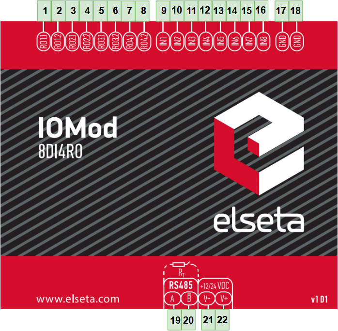
#### 2.2 Terminal connections
IOMod 8DI4RO has 22 terminals, which are depicted below:
[](https://wiki.elseta.com/uploads/images/gallery/2025-01/image-1738164493212.png)
Fig. 2.2.1 IOMod 8DI4RO terminal diagram
The description of each terminal can be found in the table below:
Table 2.2.1 Terminal Specifications
| **Terminal number**
| **Terminal name**
| **Description**
|
|---|
| 1
| RO1.1 | Relay 1 contacts (NO)
|
| 2
| RO1.2 |
| 3
| RO2.1 | Relay 2 contacts (NO)
|
| 4
| RO2.2 |
| 5
| RO3.1 | Relay 3 contacts (NO)
|
| 6
| RO3.2 |
| 7
| RO4.1 | Relay 4 contacts (NO)
|
| 8
| RO4.2 |
| 9
| IN1 | Digital inputs
|
| 10
| IN2 |
| 11
| IN3 |
| 12
| IN4 |
| 13
| IN5 |
| 14
| IN6 |
| 15
| IN7 |
| 16
| IN8 |
| 17
| COM | Common
|
| 18
| COM |
| 19
| A | RS485 input
|
| 20
| B̄ |
| 21
| V- | Power source input
|
| 22
| V+ |
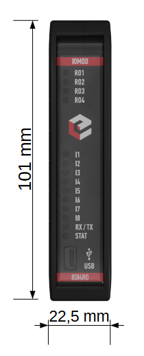
#### 2.3 Status indication
IOMod 8DI4RO has fourteen LEDs (Fig. 2.3.1), which indicate the statuses of the 8 digital inputs, 4 relay outputs, communication, and power.
[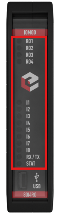](https://wiki.elseta.com/uploads/images/gallery/2025-01/image-1737725853527.png)
Fig. 2.3.1 IOMod 8DI4RO LEDs physical location
Table 2.3.1 Description of LEDs.
| **Name**
| **LED color**
| **Description**
|
|---|
| RO1-RO4
| 🟠 (orange)
| Indicates digital relay output activation
|
| IN1-IN8
| 🟠 (orange)
| Indicates digital input activation
|
| RX/TX
| 🟢 (green)
| A blinking green light indicates active communication via the RS485 interface.
|
| STAT
| 🟢 (green)
| The power source is connected to the power supply input
|
| 🔵 (blue)
| IOMod 8DI4RO is connected to an external device via a USB mini cable
|
### 3. Technical information
Table 3.1 Technical specifications.
| **System** |
|
|
| Dimension | 101 x 119 x 22.5 mm |
| Case | IP20, blend PC/ABS self-extinguishing, black |
| Working environment | Indoors
|
| Operating temperature | From -40°C to +85°C |
| Recommended operating conditions | 5 – 60°C and 20 – 80%RH; |
| Configuration | USB, RS485
|
| Firmware upgrade | USB, RS485 |
| **Electrical specifications**
|
|
|
| Inputs
| Nominal input voltage range
| 9-48VDC
|
| Isolation
| 8 X 3kV(rms)
|
| Maximum input voltage
| 60VDC
|
| Outputs
| Isolation | 4 X 3kV(rms)
|
| Rated resistive load | 5 A (at 250 VAC or 30 VDC)
|
| Rated inductive (L/R=7ms) load | 2 A (at 250 VAC or 30 VDC)
|
| Maximum switching voltage | 277 VAC
125 VDC
|
| Maximum switching current | 5 A
|
| **Power**
|
|
|
| Power Supply | 12-24 VDC / 9-33 VDC (full range) |
| Current consumption | 120mA @ 12VDC, 60mA @ 24 VDC, 30mA @ 48 VDC |
### 4. Mounting and installation
#### 4.1 Connection Diagrams
In this chapter, the various options for connecting the device are discussed.
#### 4.2 Digital inputs
The typical application of IOMod 8DI4RO inputs is shown in (Fig. 4.2.1). When the default input configuration is applied, the user will see inputs connected to +12-24V as “high” or state “1” and the input status LED will glow.
[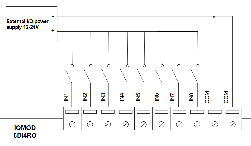](https://wiki.elseta.com/uploads/images/gallery/2025-02/image-1740126406541.png)
Fig. 4.2.1 IOMod 8DI4RO digital inputs
#### 4.3 Digital relay outputs
IOMod 8DI4RO has 4 relay outputs. Internal clamp diodes are connected to each output, making IOMod 8DI4RO ideal for driving inductive loads like relays. Maximum 5A per output is allowed. The typical application of outputs is shown in (Fig. 4.3.1).
[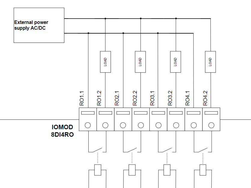](https://wiki.elseta.com/uploads/images/gallery/2025-03/image-1740995523136.png)
Fig. 4.3.1 IOMod 8DI4RO digital relay outputs
#### 4.4 Power supply
IOMod 8DI4RO needs to be powered by a 9–33 V power source. IOMod 8DI4RO power supply inputs are located next to RS485 interface inputs (Fig 4.4.1).
[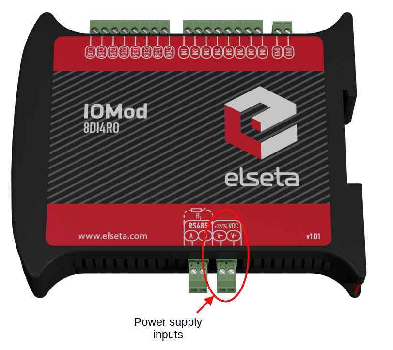](https://wiki.elseta.com/uploads/images/gallery/2025-01/image-1737977510009.png)
Fig. 4.4.1 Power supply inputs physical location
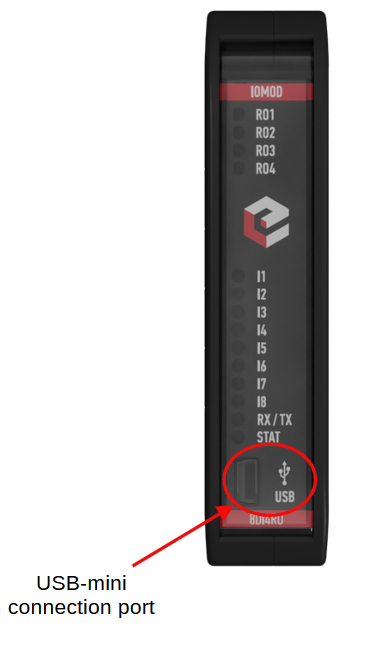
#### 4.5 USB connection
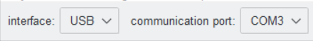
The IOMod 8DI4RO device features a USB-mini connection port, which primarily facilitates a physical connection between the IOMod and a PC. By selecting the USB interface and the appropriate communication port in the [IOMod Utility](https://wiki.elseta.com/books/tools-and-software/page/iomod-utility) (Fig. 4.5.1), users can establish a connection to control the device’s parameters. Additionally, this connection can serve as a power source for the module.
[](https://wiki.elseta.com/uploads/images/gallery/2025-01/image-1737979022373.png)
Fig. 4.5.1 IOMod Utility interface and communication port parameters
[](https://wiki.elseta.com/uploads/images/gallery/2025-01/image-1737979413045.png)
Fig. 4.5.2 IOMod 8DI4RO USB connection port physical location
### 5. Parametrization
In this section, the IOMod 8DI4RO settings configuration is described. IOMod 8DI4RO configuration is performed via IOMod Utility (the manual can be accessed [here](https://wiki.elseta.com/books/tools-and-software/page/iomod-utility)). All IOMod-related settings can be found in the "IOMod settings" tab (Fig. 5.1).
[](https://wiki.elseta.com/uploads/images/gallery/2024-10/image-1728456239496.png)
Fig. 5.1 IOMod settings tab
#### 5.1 IOMod settings
To configure IOMod 8DI4RO general settings open the "IOMod settings" tab in IOMod Utility (Fig. 5.1.1).
[](https://wiki.elseta.com/uploads/images/gallery/2025-01/image-1738236894490.png)
Fig. 5.1.1 IOMod Utility with IOMod 8DI4RO IOMod settings window opened
IOMod Utility is a tool created to configure IOMods with firmware version 2. This tool allows users to connect, configure, and diagnose IOMods such as 8DI8DO, 8DI4RO, 16DI, 8AI, 4RTD, 4CS4VS, METER, and FPI. The Utility's interface allows users to connect to IOMod via USB port or RS485. More information about this tool and its installation can be found on the documentation page IOMod Utility.
To configure IOMod 8DI4RO using IOMod Utility, first connect to a device or create a template as explained in the IOMod Utility documentation. Parameters for IOMod 8DI4RO can be configured on the IOMod settings tab. IOMod with default settings is configured as an Modbus slave device.
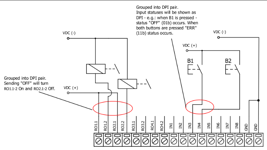
**Input/Output grouping**
Sometimes, two inputs or outputs need to be combined into double point information (DPI). Inputs and outputs can be grouped in pairs of two, where only adjacent pins can be paired, and the first pin in the pair must have an odd number. Once grouped, the second pin in the pair is no longer used, and any requests for it will result in an error. For example, RO1.1-2 and RO2.1-2 can be grouped, but after grouping, RO2.1-2 is disabled. RO2.1-2 and RO3.1-2 cannot be grouped, but RO3.1-2 and RO4.1-2 can be grouped, disabling RO4.1-2.
**Input/Output swapping**
If desired, input/output groups can be swapped. Grouped Input/Output Swapping allows you to exchange the positions of the grouped pins. After swapping, the even-numbered pin can become the first pin in the pair, and the odd-numbered pin follows. For instance, if RO1.1-2 and RO2.1-2 are grouped, you can swap their positions so that RO2.1-2 becomes the first in the pair. Parameters Group inputs/Group outputs and Swap grouped inputs/Swap grouped outputs are only available for protocols IEC101 and IEC103.
[](https://wiki.elseta.com/uploads/images/gallery/2025-02/image-1740397743070.png)
Fig. 5.1.2 Input/Output grouping example
Input/Output grouping and swapping is only available with IEC 60870-5-101 and IEC 60870-5-103 protocols.
**Input/Output inversion**
Invert inputs and Invert outputs parameters revert the state of the input/output. If the user wants the output status to display as 'ON' when the output signal is in a low state, the outputs can be logically inverted. If the user desires to turn the input status on, when that input signal is low, the user then inverts inputs logically. All input indication LEDs stay the same (are not inverted).
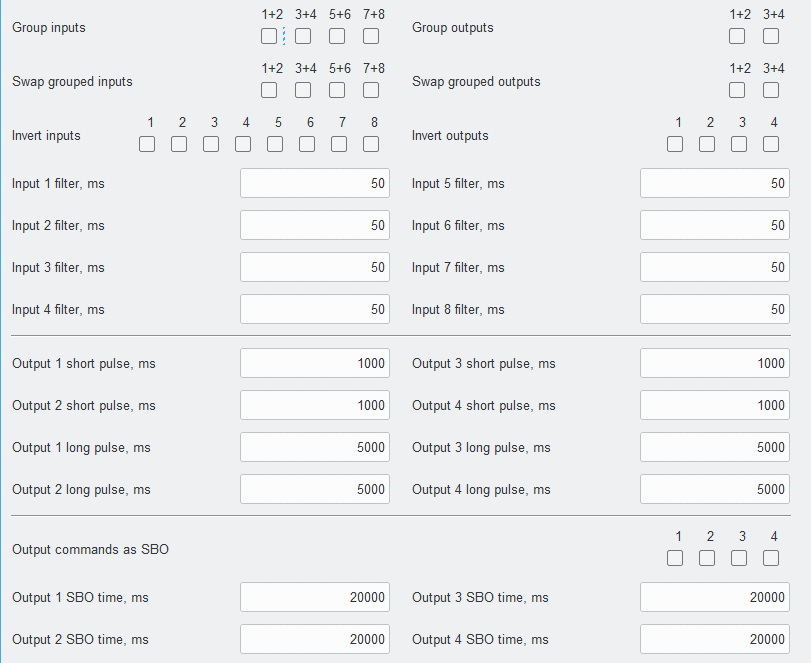
**Input filters**
Input filters define the time after which the input state is considered changed. The input filter is a simple glitch filter with time input. This filter time corresponds to the stable time that input must achieve before sending a status change. For example, if the input state is OFF and the input filter value is 50 ms, the state changes to ON and stays ON for more than 50 ms, then it will be represented as ON, but if the input state was ON for less than 50 ms it will not change and will stay as OFF. This parameter helps to filter values causing less unneeded data.
**Output pulse**
Users can configure outputs to be pulse controlled – it means that output will be turned on for the configured amount of time. When this time runs out, output is turned off. This is useful when pulse toggle relays are used. The output pulse is independent of the output grouping option and can be used on both grouped and ungrouped outputs. When output is grouped, the device will allow only one command completion at a time. If the user desires latching outputs to be used, the output pulse time is set to 0.
Unlike the Modbus RTU protocol, the IEC 60870-5-101 protocol offers options for short and long pulses. A short pulse is typically sent with qualifier 1 (QU/QL = 1), while a long pulse is usually sent with qualifier 2 (QU/QL = 2). The IEC 60870-5-103 and Modbus protocols only have pulse parameters without the ability to configure short or long pulses. The default pulse time for Modbus and IEC103 is the same as the short pulse in IEC 60870-5-101 (1000 ms).
**Select Before Operate (SBO)**
Select Before Operate (SBO) ensures that an output action (such as turning a relay on or off) is carried out only after the output has been explicitly selected. This helps prevent accidental or unauthorized operations, ensuring that the operator's intent is confirmed before acting. For example, the user wants to turn on RO1. First, they issue a select command to RO1. After the selection is acknowledged, the user sends an operation command to turn on RO1. If the command is successful, the IOMod changes the state of the relay, and the output is turned on. If there’s an issue, a **negative acknowledgement (NACK)** will be sent, and no change will occur. There is also an output SBO time option that ensures that a relay operation is not immediately executed but is instead delayed to allow for confirmation or review before the operation is carried out.
The IOMod settings' available values and ranges can be seen in the table below (Table 5.1.1).
Table 5.1.1 IOMOD 8DI4RO parameter ranges and default values
| **Parameter** | **Range** | **Default value** |
| Input \[ \] filter, ms | 1–65535 | 50 |
| Output \[ \] short pulse, ms\* | 1–65534 | 1000 |
| Output \[ \] long pulse, ms\* | 1–65534 | 5000 |
| Output \[ \] SBO time, ms\* | 1–65535 | 20000 |
\* *The parameters are defined only for the IEC 60870-5-101 communication protocol.*
#### 5.2 Device settings for **Modbus** protocol
IOMod 8DI4RO configuration is performed via IOMod Utility (the manual can be accessed [here](https://wiki.elseta.com/books/tools-and-software/page/iomod-utility)).
[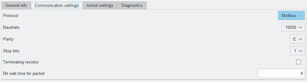](https://wiki.elseta.com/uploads/images/gallery/2025-01/image-1738054807569.png)Fig. 5.2.1 Modbus protocol communication settings tab on IOMod utility app
For Modbus protocol users can set: Link address, baudrate, parity, stop bits, terminating resistor, bit wait time (Fig. 5.2.1). See the table below for parameters range and default values (Table 5.2.1).
Table 5.2.1 Communication parameters range and default values
| **Parameter**
| **Range**
| **Default values**
|
|---|
| Link address | 1-256 | 1 |
| Baudrate | 600, 1200, 2400, 4800, 9600, 19200, 28800, 38400, 57600, 76800, 115200 | 19200 |
| Parity | None, Odd, Even, Mark, Space | Even |
| Stop bits | 1, 2 | 1 |
| Terminating resistor | Enable or disable | disabled |
| Bit wait time for packet | 8-256 | 8 |
#### 5.3 Device settings for **IEC 60870-5-101** protocol
For IEC 60870-5-101 protocol users can set: Link address, baudrate, parity, stop bits, terminating resistor and bit wait time, time synchronization timeout, link address size, ASDU size, COT size, and IOA size using the IOMod utility application. See the table below for parameter ranges and default values for IEC 60870-5-101 protocol (Table 5.3.1).
Table 5.3.1 Parameter ranges and default values of IOMod
| **Parameter**
| **Range**
| **Default values**
|
|---|
| Link address
| 1-65535\*
| 1
|
| Baudrate | 600, 1200, 2400, 4800, 9600, 19200, 28800, 38400, 57600, 76800, 115200 | 19200 |
| Parity | None, Odd, Even, Mark, Space | Even |
| Stop bits | 1, 2 | 1 |
| Terminating resistor | Enable or disable | Disabled |
| Bit wait time for packet | 8-256 | 8 |
| Time synchronization timeout (s) | 1-65535 | 300 |
| Link address size | 1, 2 | 1 |
| ASDU size | 1, 2 | 1 |
| COT size | 1, 2 | 1 |
| IOA size | 1, 2, 3 | 2 |
*\* To use Link address value greater than 256, Link address size must be set to "2".*
#### 5.4 Device settings for **IEC 60870-5-103** protocol
For IEC 60870-5-103 protocol users can set: Link address, baudrate, parity, stop bits, terminating resistor and bit wait time, time synchronization timeout, and input function using the IOMod utility application. See the table below for parameter ranges and default values for IEC 60870-5-103 protocol (Table 5.4.1)
Table 5.4.1 parameter ranges and default values of IOMod
| **Parameter**
| **Range**
| **Default values**
|
|---|
| Link address
| 1-256
| 1
|
| Baudrate | 600, 1200, 2400, 4800, 9600, 19200, 28800, 38400, 57600, 76800, 115200 | 19200 |
| Parity | None, Odd, Even, Mark, Space | Even |
| Stop bits | 1, 2 | 1 |
| Terminating resistor | Enable or disable | Disabled |
| Bit wait time for packet | 8-256 | 8 |
| Time synchronization timeout (s) | 1-65535 | 300 |
| Input function |
| 253 |
| Output command function |
| 254 |
| Output status function |
| 254 |
#### 5.5 Diagnostics
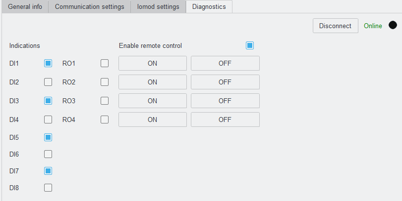
The Utility diagnostics windows allow users to connect to IOMod directly and observe the values in real-time. The 8DI4RO diagnostics window shows input and output states and also allows activation of the outputs. If an input or output is on, the Diagnostics window indicates it with a blue square next to it (unless the input/output is grouped, swapped or inverted, then they would behave in a configured way).
To turn on real-time monitoring of both Diagnostics sections, the "Connect" button to the left of the "Offline" word designation needs to be pressed. After pressing the "Connect" button the word designation of Diagnostics mode changes to "Online", the black circle starts blinking and the button name changes to "Disconnect" (Fig. 5.5.1). When a fault is detected the checkboxes are going to be checked.
[](https://wiki.elseta.com/uploads/images/gallery/2025-01/image-1738248948279.png)
Fig. 5.5.1 IOMOD utility Diagnostics tab in online mode
### 6. Communication protocols
IOMod 8DI4RO uses Modbus (RTU), IEC 60870-103 or IEC 60870-101 protocols over RS485 connection, which can be used for cable lengths up to 1500 meters and connect up to 30 devices on one line. Default Modbus, IEC 60870-103 and IEC 60870-101 settings are: 19200 bauds/s baudrate, 8E1, Slave (Link) address - 1.
Table 6.1 IOMod 8DI4RO default communication protocol settings
| Protocol
| baudrate
| parity
| stop bits
| wait byte count
| slave address
| link address size
| ASDU size
| COT size
| IOA size
| Input function
| Output command function
| Output status function
|
|---|
| Modbus
| 19200 | Even | 1 | 8 | 1 |
|
| IEC 101
| 19200 | Even | 1 | 8 | 1 | 1 | 1 | 1 | 2 |
|
| IEC 103
| 19200 | Even | 1 | 8 | 1 |
| 253 | 254 | 254 |
\*Default IOMod 8DI4RO communication protocol is Modbus
#### 6.1 Modbus RTU Operational information
Modbus RTU protocol is a simple and widely used messaging structure for serial communication. In the case of the Modbus protocol IOMod 8DI4RO will send data only after receiving correct queries from a master device. Supported Modbus function codes: FC1, FC2, FC3, FC5, FC6, FC15 and FC16.
**01 (0x01) Read Coil status**
To read the status of relay outputs (On or Off), Modbus **function 01** is used. The IOMod 8DI4RO has 4 relay outputs, with addresses ranging from 0 to 3.
**02 (0x02) Read Discrete Inputs**
Modbus **function 02** reads the status of digital inputs (On or Off). The IOMod 8DI4RO has 8 digital inputs, with addresses ranging from 8 to 15. These inputs are active-high by default.
**03 (0x03) Read Holding Registers
Function 03** allow the user to read counter/timer values related to digital inputs. The values in these registers are described in the table below (Table 6.1.1). Two types of values are stored: Pulse Counter and On Timer. The On Timer calculates the duration for which a respective input remains in its active state. It increments every second while the input is active. Pulse counter is incremented by one every time input goes from active state to deactivated state.
**05 (0x05) Write single coil** To set the state of a single relay output (On or Off), Modbus **function 05** is used. The output addresses range from 0 to 3 (the first output is address 0, last output is address 3).
**06 (0x06) Preset Single Register
Function 06** sets the value of a single register. You can set Pulse Counter and On Timer from which value to start incrementing. 0 can be set to reset Pulse Counter and On Timer.
**15 (0x15) Preset Multiple coils**
Modbus **function 15** sets the state of multiple relay outputs (On or Off) simultaneously. The output addresses range from 0 to 3 (the first output is address 0, last output is address 3).
**16 (0x16) Preset Multiple Registers
Function 16** sets the values of multiple registers. You can set Pulse Counter and On Timer from which value to start incrementing. 0 can be set to reset Pulse Counter and On Timer.
Table 6.1.1 Modbus protocol register table
| **Coil Status FC01
** |
| **Address (Dec)** | **Description** | **Data Type** | **Access** |
| 0 | read the status of relay output 01 | BOOLEAN | R |
| 1 | read the status of relay output 02 | BOOLEAN | R |
| 2 | read the status of relay output 03 | BOOLEAN | R |
| 3 | read the status of relay output 04 | BOOLEAN | R |
| **Holding Register FC03**
|
|---|
| **Address**
**(Dec)**
| **Description**
**
**
| **Data type**
| **Access**
|
|---|
| 0
| input 1 pulse count
| UINT16
| RW
|
| 1-2
| input 1 on time
| UINT32
| RW
|
| 3
| input 2 pulse count
| UINT16
| RW
|
| 4-5
| input 2 on time
| UINT32
| RW
|
| 6
| input 3 pulse count
| UINT16
| RW
|
| 7-8
| input 3 on time
| UINT32
| RW
|
| 9
| input 4 pulse count
| UINT16
| RW
|
| 10-11
| input 4 on time
| UINT32
| RW
|
| 12
| input 5 pulse count
| UINT16
| RW
|
| 13-14
| input 5 on time
| UINT32
| RW
|
| 15
| input 6 pulse count
| UINT16
| RW
|
| 16-17
| input 6 on time
| UINT32
| RW
|
| 18
| input 7 pulse count
| UINT16
| RW
|
| 19-20
| input 7 on time
| UINT32
| RW
|
| 21
| input 8 pulse count
| UINT16
| RW
|
| 22-23
| input 8 on time
| UINT32
| RW
|
| **Force Single Coil FC05**
|
|---|
| **Address**
**(Dec)**
| **Description**
**
**
| **Data type**
| **Access**
|
|---|
| 0
| set the state of a single relay output RO1
| BOOLEAN
| W
|
| 1
| set the state of a single relay output RO2
| BOOLEAN
| W
|
| 2
| set the state of a single relay output RO3
| BOOLEAN
| W
|
| 3
| set the state of a single relay output RO4
| BOOLEAN
| W
|
#### 6.2 IEC 60870-5-101 Operational Information
IEC 60870-5-101 (IEC101) is a communication protocol designed for telecontrol applications in power systems, enabling communication between a master station and slave devices (e.g., RTU).
The IOMod 8DI4RO uses the IEC101 protocol to transmit digital input (DI) status and control relay outputs (RO) in a standardized format. Each signal is assigned an Information Object Address (IOA) and a Type Identifier (TI). The protocol efficiently conveys binary status changes (e.g., on/off state of equipment or alarms) and control commands with associated timestamps, enabling reliable communication in automation systems.
Time synchronization is critical for logging events. To synchronize time, the master sends a Time Sync command C\_CS\_NA\_1 (103) with Cause of Transmission (COT) 6. According to the IEC 60870-5-101 protocol specification, time synchronization can be performed for multiple devices using broadcast messages. A master device sends a broadcast timesync command with a broadcast link address. This ensures consistent time-stamping for event recording and fault detection across the network.
Table 6.2.1 IEC 60870-5-101 protocol register table
| **IOA** | **Description** | **TI** |
| 9 | input 1 SPI event | 30 (M\_SP\_TB\_1) |
| 10 | input 2 SPI event | 30 (M\_SP\_TB\_1) |
| 11 | input 3 SPI event | 30 (M\_SP\_TB\_1) |
| 12 | input 4 SPI event | 30 (M\_SP\_TB\_1) |
| 13 | input 5 SPI event | 30 (M\_SP\_TB\_1) |
| 14 | input 6 SPI event | 30 (M\_SP\_TB\_1) |
| 15 | input 7 SPI event | 30 (M\_SP\_TB\_1) |
| 16 | input 8 SPI event | 30 (M\_SP\_TB\_1) |
| 1 | output 1 SPI event | 30 (M\_SP\_TB\_1) |
| 2 | output 2 SPI event | 30 (M\_SP\_TB\_1) |
| 3 | output 3 SPI event | 30 (M\_SP\_TB\_1) |
| 4 | output 4 SPI event | 30 (M\_SP\_TB\_1) |
| 101 | output 1 SPI command | 45 (C\_SC\_NA\_1) |
| 102 | output 2 SPI command | 45 (C\_SC\_NA\_1) |
| 103 | output 3 SPI command | 45 (C\_SC\_NA\_1) |
| 104 | output 4 SPI command | 45 (C\_SC\_NA\_1) |
Table 6.2.2 IEC 60870-5-101 protocol register table for grouped inputs/outputs
| **IOA** | **Description** | **TI** |
| 9 | input 1-2 DPI event | 31 (M\_DP\_TB\_1) |
| 11 | input 3-4 DPI event | 31 (M\_DP\_TB\_1) |
| 13 | input 5-6 DPI event | 31 (M\_DP\_TB\_1) |
| 15 | input 7-8 DPI event | 31 (M\_DP\_TB\_1) |
| 1 | output 1-2 DPI event | 31 (M\_DP\_TB\_1) |
| 3 | output 3-4 DPI event | 31 (M\_DP\_TB\_1) |
| 101 | output 1-2 DPI command | 46 (C\_DC\_NA\_1) |
| 103 | output 3-4 DPI command | 46 (C\_DC\_NA\_1) |
*\* SPI - single-point information, DPI - double-point information*
To read single-point inputs/outputs, TI 30 is used, which provides single-point information with time tag. If double-point inputs/outputs need to be read, TI 31 is used, which provides information with time tag.
TI 45 is used to send a command to a single-point output, whereas TI 46 is used to send a command to a double-point output. If outputs are grouped, to enable or disable relay outputs, the master (controlling station) has to send commands with TI 46 (Table 6.2.2). DPI signals consist of two bits of information, allowing for four possible states:
Table 6.2.2 Double-point states
| **Value** | **State** |
| 00 | intermediate |
| 01 | off |
| 10 | on |
| 11 | error |
#### 6.2 IEC 60870-5-103 Operational Information
IEC 60870-5-103 is a communication protocol specifically designed for telecontrol and automation systems in the electrical power industry, particularly for substation automation. IEC 60870-5-103 is more specialized for applications related to protection, control, and monitoring in electrical substations.
Time synchronization is critical for logging events. To synchronize time, the master sends a Time Sync command with function 0 and Cause of Transmission (COT) 8. According to the IEC 60870-5-103 protocol specification, time synchronization can be performed for multiple devices using broadcast messages. For broadcast time synchronization, the master device sends a periodic signal with a time stamp to synchronize the system time of slave devices. If synchronization fails, devices default to their local system time until they successfully resynchronize.
Table 6.3.1 IEC 60870-5-103 protocol register table
| **Type** | **Function**
| **INF**
| **Description**
|
| 1 (M\_TTM\_TA\_3) | 253
| 1
| input 1 event
|
| 1 (M\_TTM\_TA\_3) | 253
| 2
| input 2 event
|
| 1 (M\_TTM\_TA\_3) | 253
| 3
| input 3 event
|
| 1 (M\_TTM\_TA\_3) | 253
| 4
| input 4 event
|
| 1 (M\_TTM\_TA\_3) | 253
| 5
| input 5 event
|
| 1 (M\_TTM\_TA\_3) | 253
| 6
| input 6 event
|
| 1 (M\_TTM\_TA\_3) | 253
| 7
| input 7 event
|
| 1 (M\_TTM\_TA\_3) | 253
| 8
| input 8 event
|
| 1 (M\_TTM\_TA\_3) | 254
| 1
| output 1 event
|
| 1 (M\_TTM\_TA\_3) | 254
| 2
| output 2 event
|
| 1 (M\_TTM\_TA\_3) | 254
| 3
| output 3 event
|
| 1 (M\_TTM\_TA\_3) | 254
| 4
| output 4 event
|
| 1 (M\_TTM\_TA\_3) | 254
| 1
| output 1 command
|
| 1 (M\_TTM\_TA\_3) | 254
| 2
| output 2 command
|
| 1 (M\_TTM\_TA\_3) | 254
| 3
| output 3 command
|
| 1 (M\_TTM\_TA\_3) | 254
| 4
| output 4 command
|
Table 6.3.2 IEC 60870-5-103 protocol register table for grouped inputs/outputs
| **Type** | **Function** | **INF** | **Description** |
| 1 (M\_TTM\_TA\_3) | 253 | 1 | input 1-2 event |
| 1 (M\_TTM\_TA\_3) | 253 | 3 | input 3-4 event |
| 1 (M\_TTM\_TA\_3) | 253 | 5 | input 5-6 event |
| 1 (M\_TTM\_TA\_3) | 253 | 7 | input 7-8 event |
| 1 (M\_TTM\_TA\_3) | 254 | 1 | output 1-2 event |
| 1 (M\_TTM\_TA\_3) | 254 | 3 | output 3-4 event |
| 1 (M\_TTM\_TA\_3) | 254 | 1 | output 1-2 command |
| 1 (M\_TTM\_TA\_3) | 254 | 3 | output 3-4 command |
Function 253 is responsible for input event detection. IOMod continuously monitors its input channels to detect changes. Function 254 is responsible for output event detection and command sending. These two functions are default in IOMod utility app (Fig. 6.3.1) but can be modified according to needs.
[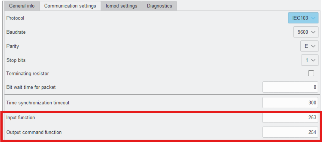](https://wiki.elseta.com/uploads/images/gallery/2025-02/image-1740147111377.png)
Fig. 6.3.1 IOMod utility input/output functions location
If outputs are grouped, to enable or disable relay outputs, the master (controlling station) has to send commands with function type 254 (Table 6.3.1). DPI signals consist of two bits of information, allowing for four possible states:
Table 6.3.3 Double-point states
| **Value** | **State** |
| 00 | intermediate |
| 01 | off |
| 10 | on |
| 11 | error |