# How To
# Connect to WCC Lite
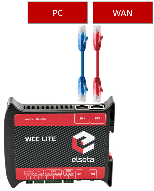
In order to connect to the WCC Lite:
1. Power up the WCC Lite
2. Once the WCC Lite boots up, plug an ethernet cable into the **ETH0** port.
3. Connect the other end of the cable to the Ethernet interface of your PC/Mac
4. Make sure DHCP is enabled on your Ethernet interface
5. Open [https://192.168.1.1](http://192.168.1.1/) in your web browser (username: root, password: wcclite)
Remember, by default WCC Lite interfaces have following designations
Interface
Designation
Specs
ETH0
LAN
DHCP server, without firewall protection by default.
ETH1
WAN
DHCP client, strict firewall rules
# WAN IP Setup
## Description
One o the first steps in RTU/Datalogger setting up is to prepare connection to internet or a specific private network over Ethernet or GSM. This article describes WAN over Ethernet connection setup.
[](https://wiki.elseta.com/uploads/images/gallery/2020-10/image-1601990457991.png)
## Setting WAN IP
1. Go to Network → Interfaces → Edit (WAN)
2. Select protocol - Static address and click on Switch protocol
3. Enter addresses of your WAN network and click on Save & Apply
Example:
Video how to setup WAN IP address:
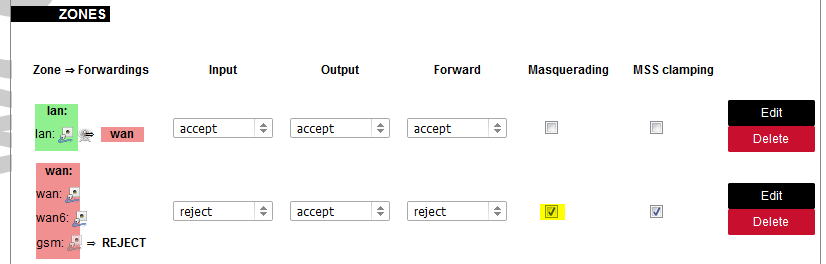
# Enable Internet or WAN for connected devices
In order to enable connected devices communication through the router it is needed to enable Masquerading for outgoing packets on WAN interface:
1. Go to Network → Firewall→ General settings
2. Select Masquerading on WAN interface and click on Save & Apply
[](https://wiki.elseta.com/uploads/images/gallery/2020-10/image-1601989913581.png)
A short video about this:
# Capture packets using tcpdump
### Description
This article describes how to log packets using tcpdump.
### Installing tcpdump
Before starting, you need to install required packages. **Tcpdump** and **Libpcap**. These packages can be found attached to the article.
To install, you need to upload the packages to your **WCCLite** /tmp/ directory. You can achieve this by using **scp** or any other software that has scp compatibility, for example: WinSCP, PSCP, FileZilla.
We are going to upload using **scp.**
1. Navigate to the directory where **libpcap** is.
2. Open the command terminal in that directory.
3. Execute command: *scp libpcap\_1.7.4-1\_ar71xx.ipk root@192.168.1.1:/tmp/*
4. It will ask you for the password. Enter the default wcclite password - *wcclite*.
[](https://wiki.elseta.com/uploads/images/gallery/2021-08/image-1627892977493.png)
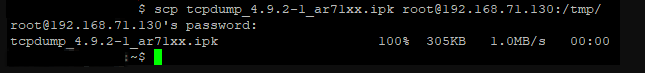
1. Navigate to the directory where **tcpdump** is.
2. Open the command terminal in that directory.
3. Execute command: *scp tcpdump\_4.9.2-1\_ar71xx.ipk root@192.168.1.1:/tmp/*
4. It will ask you for the password. Enter the default wcclite password - *wcclite*.
[](https://wiki.elseta.com/uploads/images/gallery/2021-08/image-1627893107060.png)
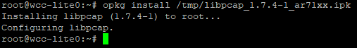
After uploading the packages, you need to install them.
1. Connect to the **WCCLite** using an ssh client. We recommend using [*putty*](https://www.chiark.greenend.org.uk/~sgtatham/putty/latest.html)
2. Execute command: *opkg install /tmp/libpcap\_1.7.4-1\_ar71xx.ipk* to install **libpcap**
3. If successful you will get this message.
[](https://wiki.elseta.com/uploads/images/gallery/2021-08/image-1627890317789.png)
Now to install **tcpdump**:
1. Execute: *opkg install /tmp/tcpdump\_4.9.2-1\_ar71xx.ipk* to install **tcpdump.**
2. If successful you will get this message.
[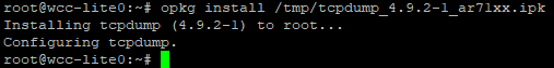](https://wiki.elseta.com/uploads/images/gallery/2021-08/image-1627890567145.png)
To check if everything installed correctly, execute this command: *tcpdump --v*
[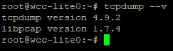](https://wiki.elseta.com/uploads/images/gallery/2021-07/image-1627654474783.png)
Now **Tcpdump** has been successfully installed.
### Running tcpdump
To run **tcpdump** you need to give it specific options. You can find all of them in the [manual](https://www.tcpdump.org/manpages/tcpdump.1.html). Here are some of the more frequent ones:
**Switch**
**Syntax**
**Description**
-i any
tcpdump -i any
Capture from all interfaces
-i eth0
tcpdump -i eth0
Capture from specific interface
-D
tcpdump -D
Show available interfaces
-w
tcpdump -i eth0 -w capture.pcap
Save capture to file (.pcap for reading it with *Wireshark* or other packet analysis tools)
-c
tcpdump -i eth0 -c 100
Capture first 100 packets and exit
-n
tcpdump -n -i eth0
Do not resolve host names
port
tcpdump -i eth0 port 2404
Capture traffic from a defined port only
host
tcpdump host 192.168.1.100
Capture packets from specific host
After you write your specific command you execute it via the console.
Here is shown ***tcpdump -i wwan0 -n.*** This command shows all traffic that goes through the gsm interface.
[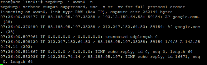](https://wiki.elseta.com/uploads/images/gallery/2021-08/image-1627889271177.png)
#### Examples
Capture packets that go through gsm interface and write a new file to /tmp/capture-<count>.pcap file every 3600 seconds.
tcpdump -i any -n port 2404 -w /tmp/capture-%H.pcap -G 3600
Capture packets that are on port 2404 that go through all interfaces and save a new file to /tmp/capture-<count>.pcap every 3600 seconds.
### Downloading packet files
If you save your **tcpdump** files, you need to download them from the **WCCLite.** This can be achieved by using **scp** or any software that has scp compatibility, for example: WinSCP, PSCP, FileZilla.
We are going to use **scp** to download the file.
1. Open the command terminal on your computer.
2. Execute command with the location of your *packet dump* file and directory where to save it. *scp root@192.168.1.1:/<dump directory>/<dump name> <directory where to save it>*
3. It will ask for the **WCCLite** password. Enter the default password - *wcclite*.
4. If successful the file will appear in the determined location.
Example of the command.
[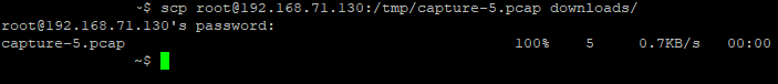](https://wiki.elseta.com/uploads/images/gallery/2021-08/image-1627903702658.png "Example of the command")
### Files
1. PuTTy ssh software [Download](https://www.chiark.greenend.org.uk/~sgtatham/putty/latest.html)
2. WinSCP software [Download](https://winscp.net/eng/index.php)
3. TCPDump [manual](https://www.tcpdump.org/manpages/tcpdump.1.html)
4. Libpcap [Download](https://wiki.elseta.com/attachments/7)
5. Tcpdump [Download](https://wiki.elseta.com/attachments/8)# IOMod setup with WCC Lite
In this chapter you will learn how to connect all kinds of Elseta IOMods to the WCC Lite
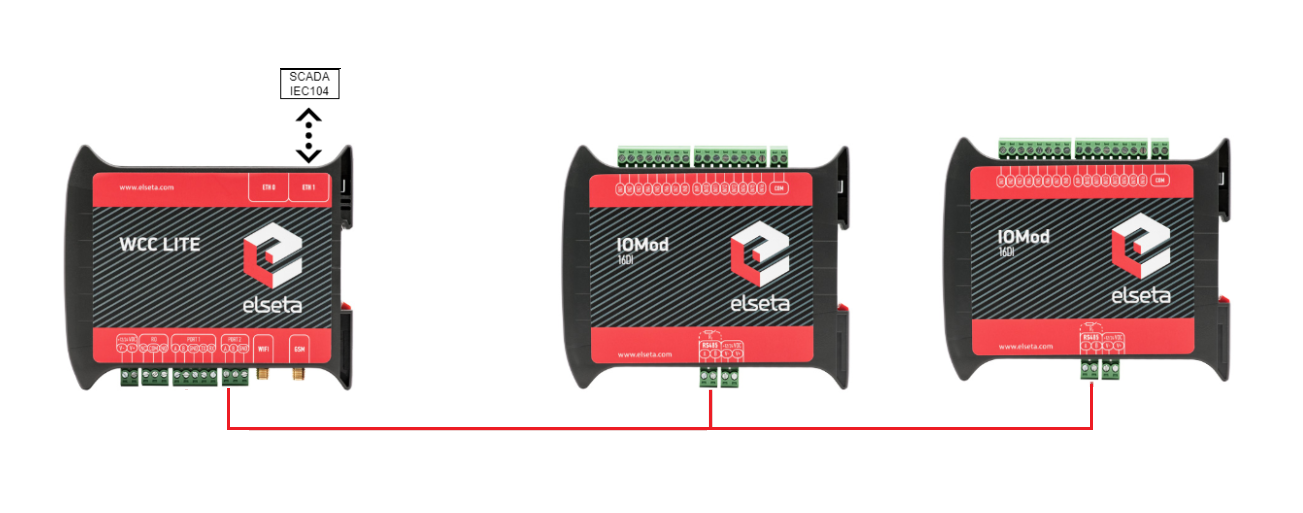
# Connecting IOMod 16DI to the WCC Lite
### Description
This article describes connecting and configuring IOMOD 16DI to the WCC Lite using IEC101, IEC103, and Modbus RTU.
[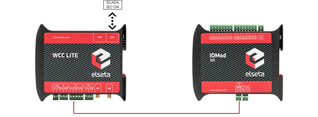](https://wiki.elseta.com/uploads/images/gallery/2021-12/image-1638361303133.png)
Typical connection schematic for IOMod 16DI
WCC Lite can be connected to IOMod 16DI via PORT1 or PORT2.
### Preparing the configuration
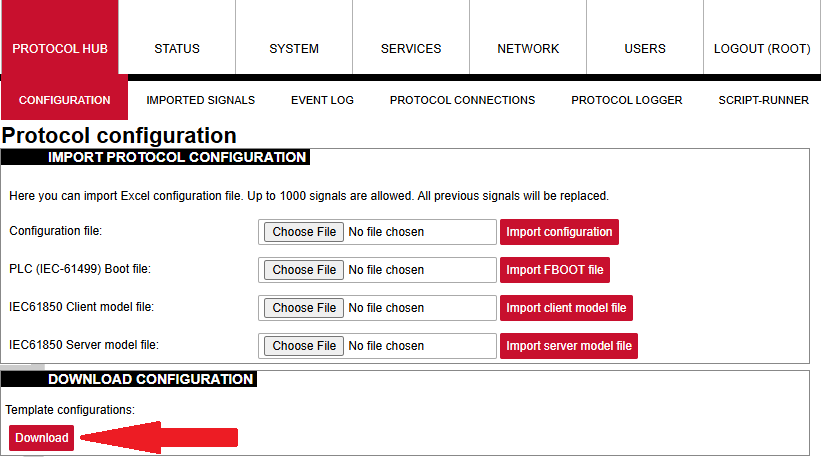
First, you need to configure WCC Lite using any spreadsheet editing program. The configuration templates can be found on the WCC Lite web: Protocol Hub --> Configuration. At the bottom of the page, there will be a *Download* button for template configurations.
[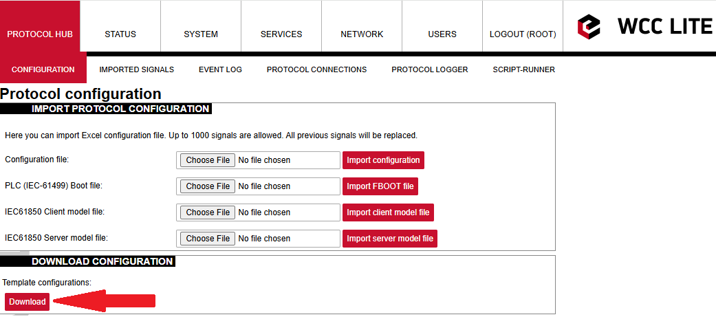](https://wiki.elseta.com/uploads/images/gallery/2025-04/image-1745391989421.png)
You can download the example configuration for each firmware version at the bottom of the article, or create your own using these links:
- For [IEC103 ](https://wiki.elseta.com/attachments/650)
- For [IEC101](https://wiki.elseta.com/attachments/649)
- For [Modbus](https://wiki.elseta.com/attachments/648)
You need to configure the Devices and Signals sheets before continuing. After downloading template configurations, open the phub templates folder. You will see that there are different template folders for each IOMod:
[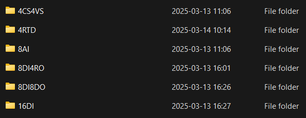](https://wiki.elseta.com/uploads/images/gallery/2025-03/image-1741952060514.png)
To select the correct configuration, check the sticker on the back of the IOMod. There, you will find which protocol to use according to Factory FW type. For example, if you have IOMod 16DI with IEC103 FW, select configuration iomod\_16DI\_IEC103\_to\_IEC104\_DNP3\_Modbus\_SCADA.
IOMOD needs to be configured, as in the Excel configuration. If templates are being used, default parameters should be set for the IOMOD. IOMODs with firmware version 1 are configured via PuTTY or other SSH programs using the USB port on the device's front panel. This can be done following the [IOMod 16DI user manual](https://wiki.elseta.com/attachments/647).
IOMOD also has a series of parameters that can be configured directly for the IOMOD without changing the WCC Lite configuration. Each IOMOD has its unique parameters, which can be seen on the configuration menu.
[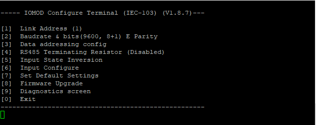](https://wiki.elseta.com/uploads/images/gallery/2025-04/image-1745916922979.png)
A new menu opens by clicking \[6\], allowing the user to configure the 16DI inputs. Input grouping allows grouping of neighbour inputs, the first being an odd-numbered input. This then makes the grouped inputs a double-point input. When making an Excel configuration for WCC Lite with double-point information, the even-numbered input signal should be deleted, and the odd-numbered input signal should be configured as a double-point signal.
The user can also change the input filter time. This parameter is set in milliseconds and determines the time after which the input is represented with the changed state. For example, if the filter time is 1000ms, and the input has been on for 500ms, the state won't change from OFF to ON. This is relevant when seeking to avoid unnecessary data.
### Uploading configuration
Template configurations can work with default settings without any further changes. These template configurations can also be used to configure protocols like Modbus-master and DNP3. Configuration can be modified according to the functionality needed. For that, you can rely on the examples given in the links above (Preparing the configuration). If you need to specify different IEC104 slave settings, you can do that by changing the Excel configuration. By changing settings such as *info\_address* or *data\_type,* you can adapt the IEC104 slave to work as needed. To test this example, specify your computer's IP address in the Excel configuration for the IEC104 slave.
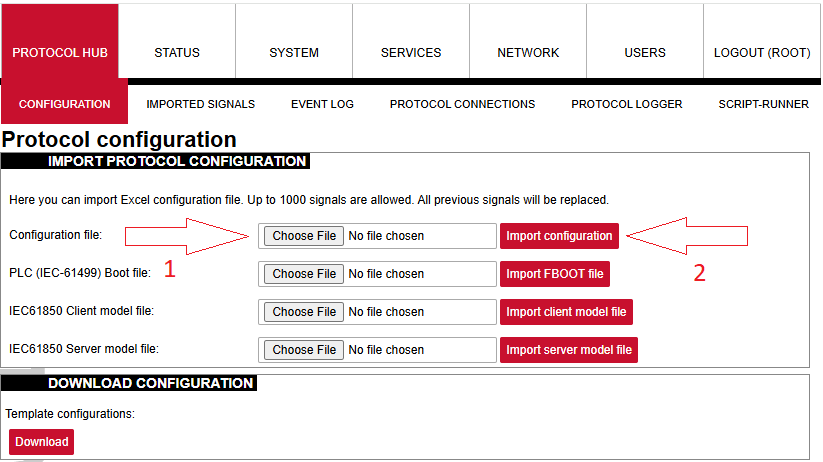
After the configuration is ready, upload it to WCC Lite (Configuration --> Choose file --> Import configuration):
[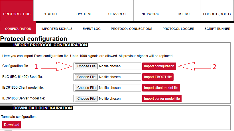](https://wiki.elseta.com/uploads/images/gallery/2025-04/image-1745396616653.png)
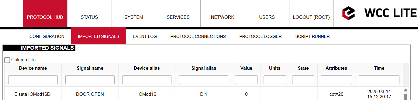
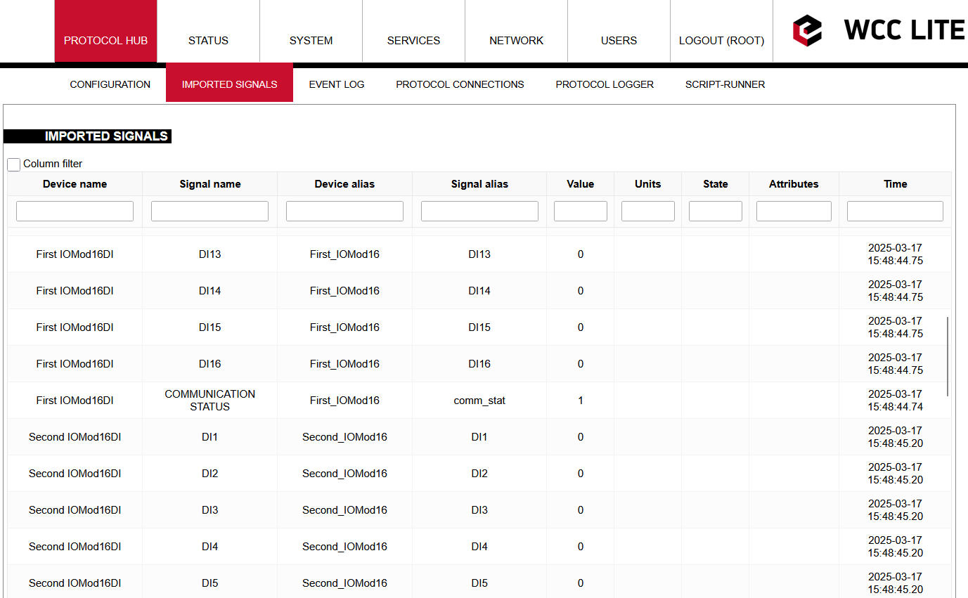
After the upload is done and no errors were detected, you should see all imported signals (Protocol Hub --> Imported signals):
[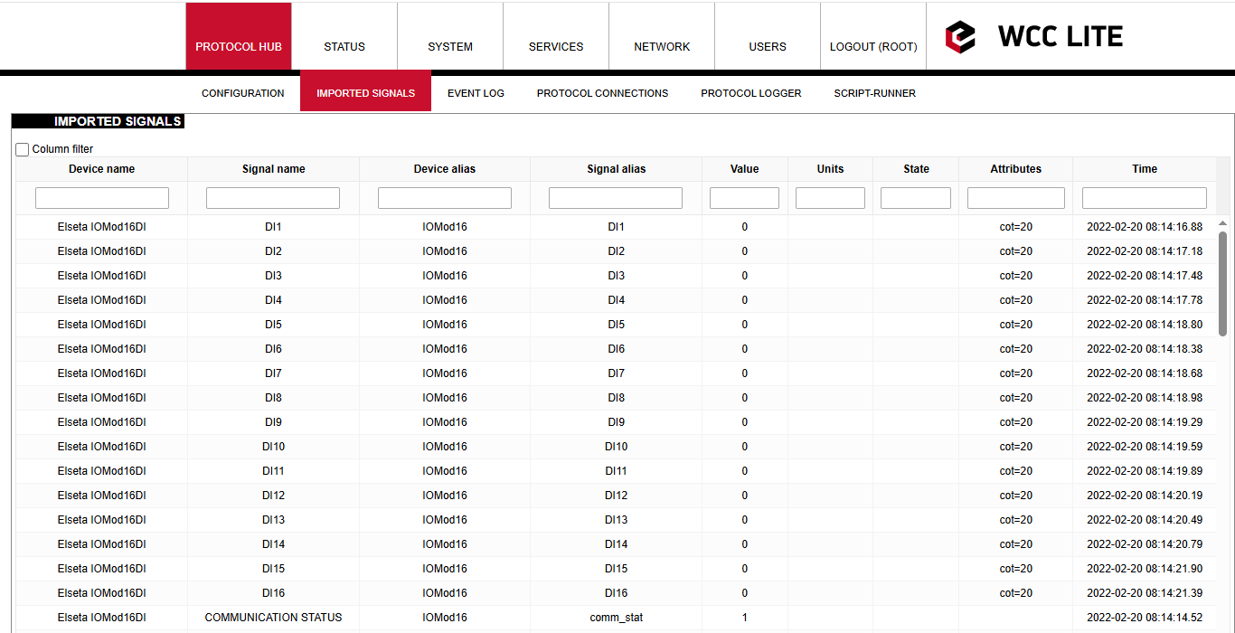](https://wiki.elseta.com/uploads/images/gallery/2025-04/image-1745398645461.png)
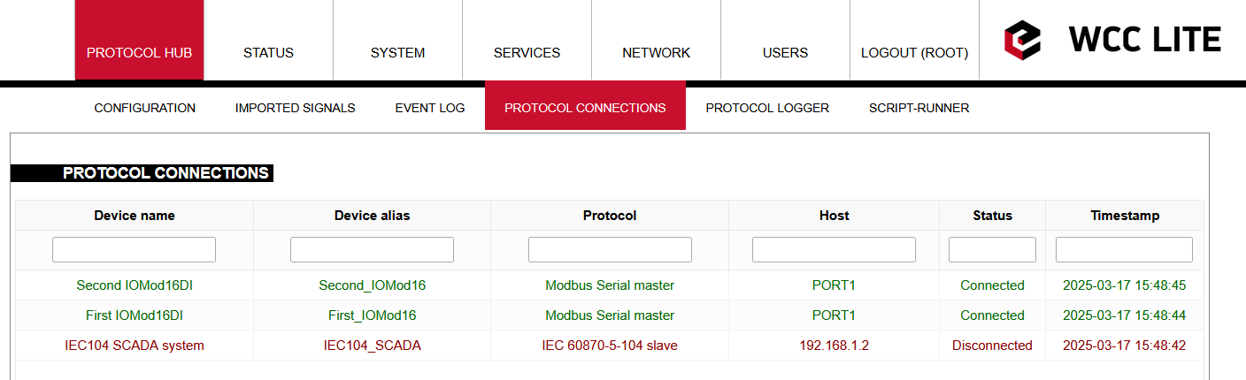
Before doing anything further, you should also check for protocol connections if IOMod 16DI is connected to WCC Lite via PORT1. Go to Protocol connections, where you can see all the connected slave and master protocol devices:
[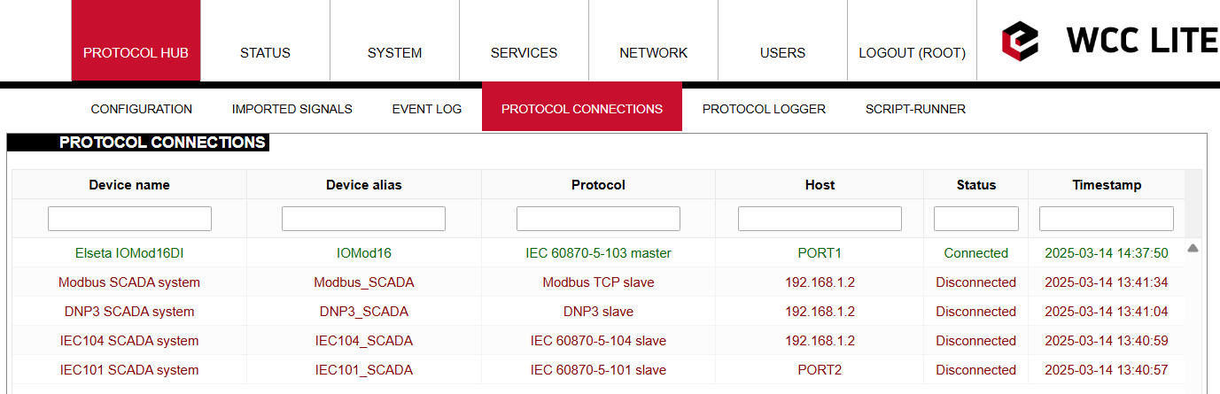](https://wiki.elseta.com/uploads/images/gallery/2025-03/image-1741956075977.png)
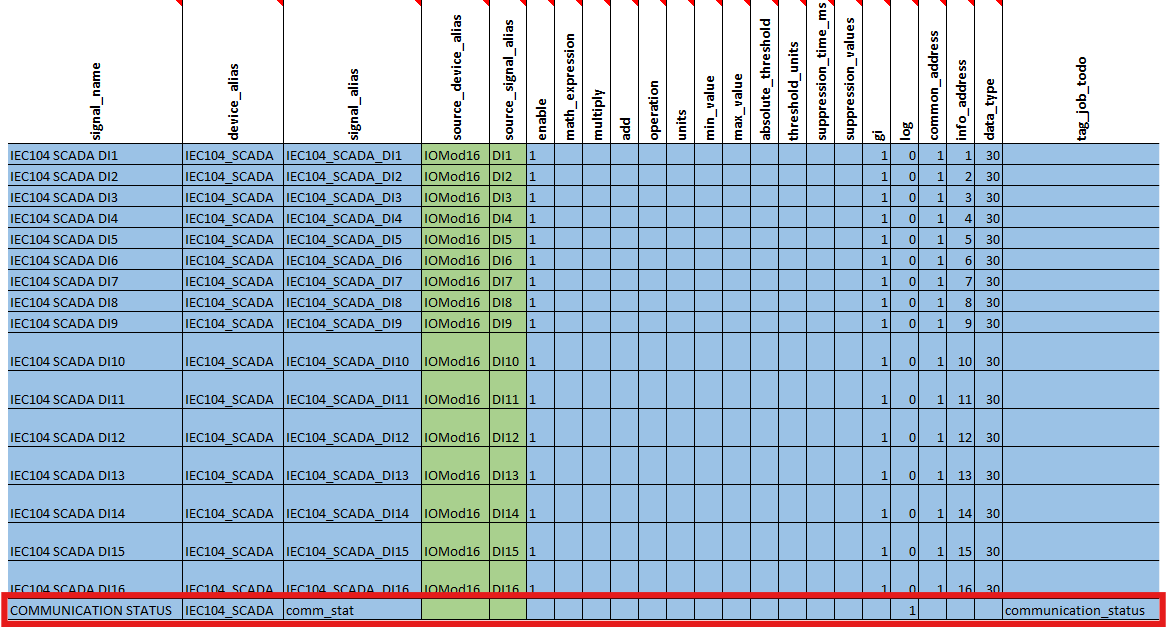
You can also change signal names according to your needs:
[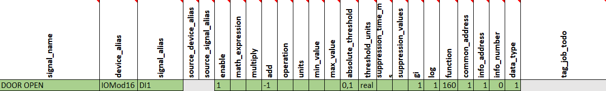](https://wiki.elseta.com/uploads/images/gallery/2025-03/image-1741958154237.png)
[](https://wiki.elseta.com/uploads/images/gallery/2025-03/image-1741958188810.png)
In every signals sheet, you can see a signal named COMMUNICATION STATUS. It is an indicator that shows whether the service is running and whether there is a connection with the device.
[](https://wiki.elseta.com/uploads/images/gallery/2025-03/image-1741961424044.png)
If everything is connected and service is running, COMMUNICATION STATUS should display 1. Otherwise, if not, it should display 2.
[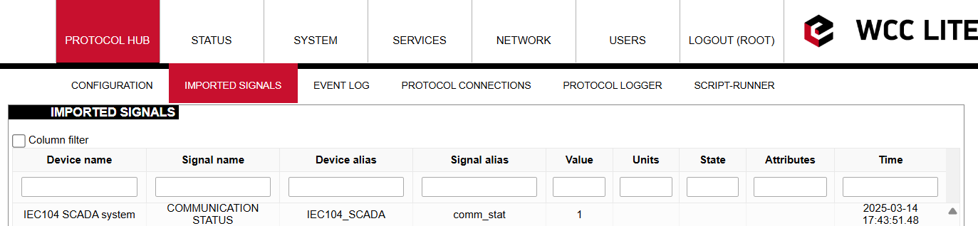](https://wiki.elseta.com/uploads/images/gallery/2025-03/image-1741962018305.png)
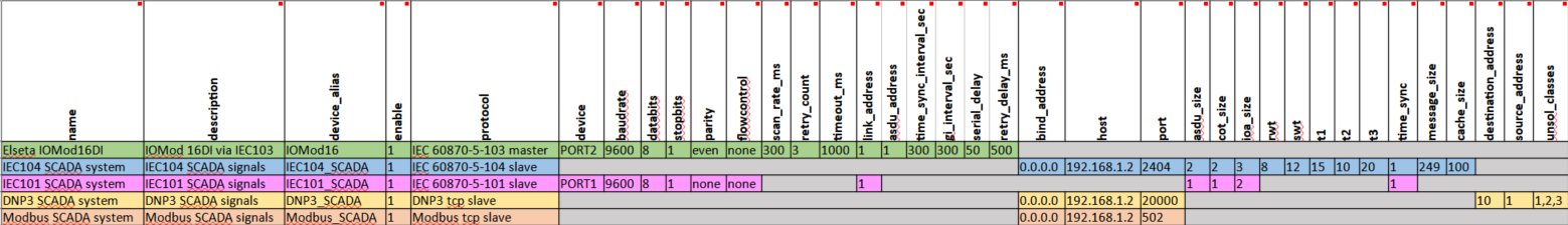
If IOMOD needs to be connected to another port, this could also be changed in the configuration. On the Device sheet, change the Device value from PORT1 to PORT2:
[](https://wiki.elseta.com/uploads/images/gallery/2025-04/image-1745412798424.png)
When configuring ports, please note that there can be 2 of the same protocol on the same port (with different IDs, link addresses, etc.), but there cannot be 2 different protocols on the same port.
### Simulating SCADA via Vinci software
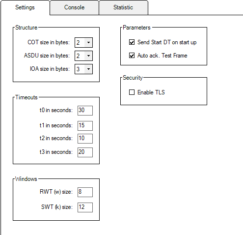
After uploading the Excel configuration, you can simulate SCADA using Vinci software. To simulate an IEC 104 slave, you need to choose the IEC 60870-5-104 protocol and Master(Client) mode and press start. In the *Settings* tab, check Structure, Timeouts and Windows values to match the Excel configuration.
[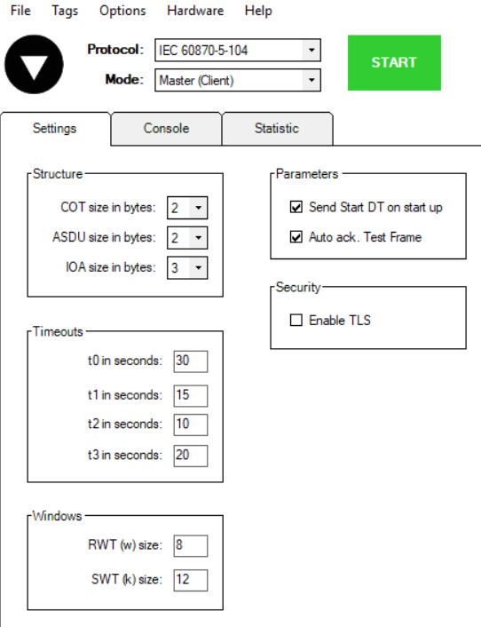](https://wiki.elseta.com/uploads/images/gallery/2025-03/image-1741958787156.png)
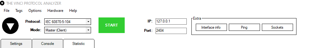
Then set the correct IP address and Port at the top of the program page. **Port** for IEC104 should be 2404, and **IP address** should match your WCC Lite IP address (default address is 192.168.1.1 if it's connected to your computer via an Ethernet cable).
[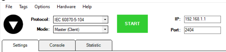](https://wiki.elseta.com/uploads/images/gallery/2022-12/image-1671616037090.png)
After clicking start, you should check the protocol connections tab again to see if the IEC104 slave is connected.
[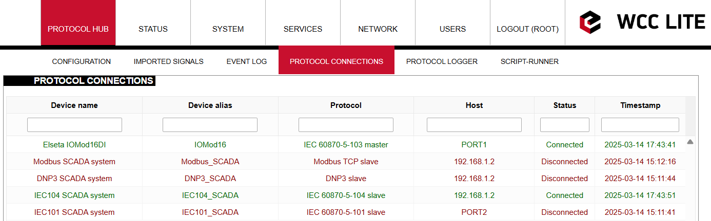](https://wiki.elseta.com/uploads/images/gallery/2025-03/image-1741959943539.png)
Once the IEC104 slave is connected, the console tab in Vinci software should look something like this:
[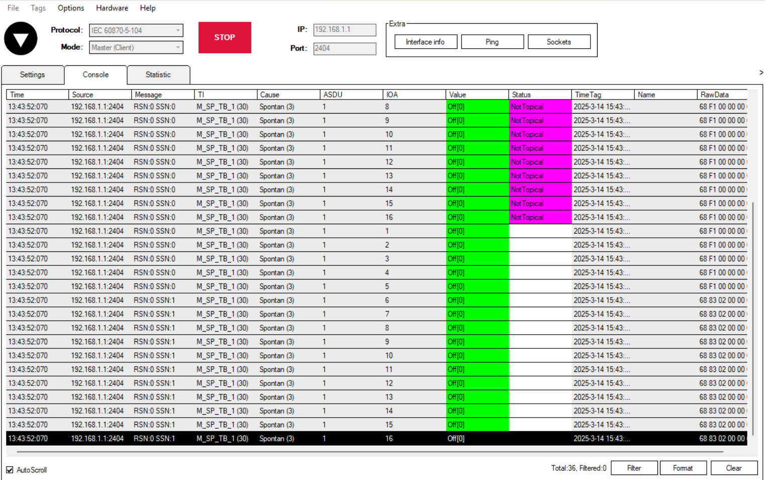](https://wiki.elseta.com/uploads/images/gallery/2025-03/image-1741959869508.png)
# Connecting two IOMod 16DI
### Description
This article describes how to connect and configure two IOMods 16DI to the WCC Lite using IEC103, and Modbus RTU.
[](https://wiki.elseta.com/uploads/images/gallery/2022-12/image-1670317371132.png)
Typical connection schematic for two IOMod 16DI
WCC Lite can be connected to two IOMod 16DI via PORT1 or PORT2.
### Preparing the configuration
At first, you need to make a configuration for the WCC Lite. This can be done using any spreadsheet editing program. Templates for configuration can be found on the WCC Lite web. Protocol Hub --> Configuration. At the bottom of the page, there will be a *Download* button for template configurations.
[](https://wiki.elseta.com/uploads/images/gallery/2025-05/image-1747664622386.png)
You need to configure the Devices and Signals sheets before continuing. These template configurations can also be used to configure protocols like Modbus-master and DNP3. Configuration can be modified according to the functionality needed. In this case, the *Device* sheet will only have three devices: WCC Lite and two IOMod 16DI. It is important to use only one protocol for each port, otherwise configuration will not work.
[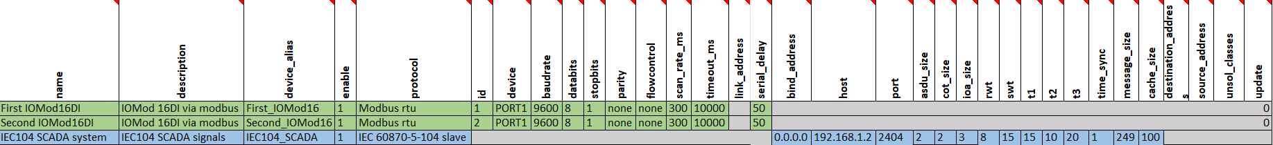](https://wiki.elseta.com/uploads/images/gallery/2025-03/image-1742211726175.png)
You can download the example configuration for each firmware version at the bottom of the article, or create your own using these links:
- For [IEC103](https://wiki.elseta.com/attachments/650)
- For [IEC101](https://wiki.elseta.com/attachments/649)
- For [Modbus](https://wiki.elseta.com/attachments/648)
You need to configure the devices and signal sheets before continuing. After downloading template configurations, open the phub templates folder. You will see that there are different template folders for each IOMod:
[](https://wiki.elseta.com/uploads/images/gallery/2025-03/image-1741952060514.png)
To select a correct configuration, check the sticker on the back of the IOMod. There, you will find which protocol to use according to Factory FW type. For example, if you have IOMod 16DI with IEC103 FW, select configuration iomod\_16DI\_IEC103\_to\_IEC104\_DNP3\_Modbus\_SCADA.
IOMOD needs to be configured, as in the Excel configuration. If templates are being used, default parameters should be set for the IOMOD. IOMODs with firmware version 1 are configured via PuTTY or other SSH programs using the USB port on the device's front panel. This can be done following the [IOMod 16DI user manual](https://wiki.elseta.com/attachments/647).
IOMOD also has a series of parameters that can be configured directly for the IOMOD without changing the WCC Lite configuration. Each IOMOD has its unique parameters, which can be seen on the configuration menu.
[](https://wiki.elseta.com/uploads/images/gallery/2025-04/image-1745916922979.png)
A new menu opens by clicking \[6\], allowing the user to configure the 16DI inputs. Input grouping allows grouping of neighbour inputs, the first being an odd-numbered input. This then makes the grouped inputs a double-point input. When making an Excel configuration for WCC Lite with double-point information, the even-numbered input signal should be deleted, and the odd-numbered input signal should be configured as a double-point signal.
The user can also change the input filter time. This parameter is set in milliseconds and determines the time after which the input is represented with the changed state. For example, if the filter time is 1000ms, and the input has been on for 500ms, the state won't change from OFF to ON. This is relevant when seeking to avoid unnecessary data.
### Uploading configuration
Template configurations can work with default settings without any further changes. These template configurations can also be used to configure protocols like Modbus-master and DNP3. Configuration can be modified according to the functionality needed. For that, you can rely on the examples given in the links above (Preparing the configuration). If you need to specify different IEC104 slave settings, you can do that by changing the Excel configuration. By changing settings such as *info\_address* or *data\_type,* you can adapt the IEC104 slave to work as needed. To test this example, specify your computer's IP address in the Excel configuration for the IEC104 slave.
After the configuration is ready, upload it to WCC Lite (Configuration --> Choose file --> Import configuration):
[](https://wiki.elseta.com/uploads/images/gallery/2025-05/image-1747727323347.png)
After the upload is done and no errors were detected, you should see all imported signals (Protocol Hub --> Imported signals):
[](https://wiki.elseta.com/uploads/images/gallery/2025-03/image-1742212283072.png)
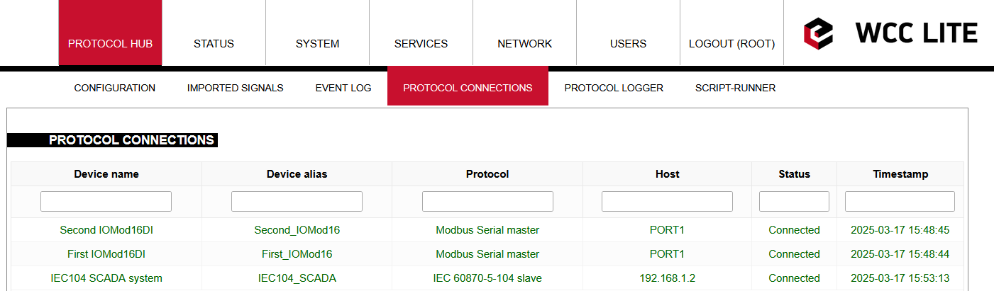
Before doing anything further, you should also check for protocol connections if both IOMod 16DI are connected to WCC Lite via PORT1. Go to Protocol connections, where you can see all the connected slave and master protocol devices:
[](https://wiki.elseta.com/uploads/images/gallery/2025-03/image-1742212346712.png)
You can also change signal names according to your needs:
[](https://wiki.elseta.com/uploads/images/gallery/2025-03/image-1741958154237.png)
[](https://wiki.elseta.com/uploads/images/gallery/2025-03/image-1741958188810.png)
In every signals sheet, you can see a signal named COMMUNICATION STATUS. It is an indicator that shows whether the service is running and whether there is a connection with the device.
[](https://wiki.elseta.com/uploads/images/gallery/2025-03/image-1741961424044.png)
If everything is connected and service is running, COMMUNICATION STATUS should display 1. Otherwise, if not, it should display 2.
[](https://wiki.elseta.com/uploads/images/gallery/2025-03/image-1741962018305.png)
If IOMOD needs to be connected to another port, this could also be changed in the configuration. On the Device sheet, change the Device value from PORT1 to PORT2:
[](https://wiki.elseta.com/uploads/images/gallery/2025-04/image-1745412798424.png)
When configuring ports, please note that there can be 2 of the same protocol on the same port (with different IDs, link addresses, etc.), but there cannot be 2 different protocols on the same port.
### Connecting IEC104-slave via Vinci
After Excel and USB configurations, you can connect to the device using the Vinci software. To simulate an IEC 104 slave, you need to choose the IEC 60870-5-104 protocol and Master(Client) mode and press start. In the *Settings* tab, check Structure, Timeouts and Windows values to match Excel configuration.
[](https://wiki.elseta.com/uploads/images/gallery/2022-12/image-1670320501413.png)
Then set the correct IP address and Port at the top of the program page. **Port** for IEC104 should be 2404, and **IP address** should match your WCC Lite IP address.
[](https://wiki.elseta.com/uploads/images/gallery/2022-12/image-1670320526682.png)
After clicking start, you should check the protocol connections tab again to see if the IEC104 slave is connected.
[](https://wiki.elseta.com/uploads/images/gallery/2025-03/image-1742212491674.png)
Once the IEC104 slave is connected, the console tab in Vinci software should look something like this:
[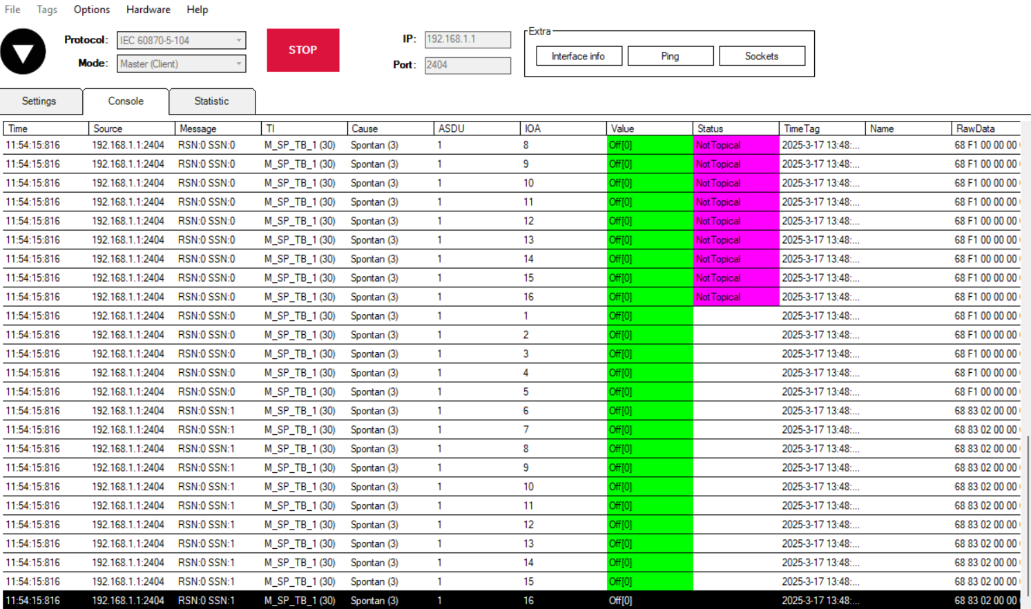](https://wiki.elseta.com/uploads/images/gallery/2025-03/image-1742212470033.png)
If you want to configure IOMod 16DI, you should refer to -> [IOMod 16DI User Manual](https://wiki.elseta.com/attachments/646).
# Connecting 2x 8DI8DO IOMod to the WCC Lite
### Description
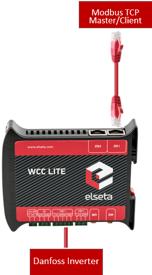
This article describes connecting and configuring two IOMOD 8DI8DO to the WCC Lite PORT1.
Each IOMod must be configured to match the Excel configuration. If using the template configuration, default parameters should be applied to the IOMod. IOMODs with firmware version 2 are configured using the [IOMod utility application](https://wiki.elseta.com/books/tools-and-software/page/iomod-utility) either via the USB port on the device's front panel or via the RS-485. Refer to the [IOMod 8DI8DO user manual](https://wiki.elseta.com/books/iomod-8di8do/page/iomod-8di8do-user-manual)
Each IOMOD has its own set of parameters that can be adjusted without modifying the WCC Lite configuration. These can be accessed through the device's configuration menu.
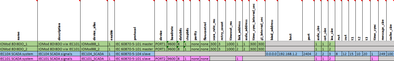
If you are creating a custom configuration, especially when multiple devices of the same type are connected to the same port, make sure that the *Device\_alias* values are unique for each device in the Devices sheet. Link address values must be different. Additionally, in the Signals sheet, Device\_alias and Signal\_alias combinations must not be duplicated across different devices.
### Uploading configuration
The configuration can be modified to suit your specific needs. You can use the example provided above ([2x\_8DI8DO.xlsx](https://wiki.elseta.com/attachments/679)) as a reference. If different IEC104 slave settings are required, they can be modified in the Excel configuration. For example, you can adjust settings such as info\_address or data\_type to match the desired behavior of the IEC104 slave. To test this example, specify your computer's IP address in the IEC104 slave’s host column in the Excel file.
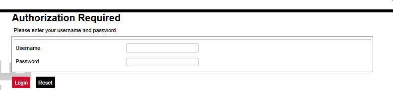
Once the configuration is ready, upload it to WCC Lite via Configuration --> Choose file --> Import configuration.
[](https://wiki.elseta.com/uploads/images/gallery/2025-04/image-1745396616653.png)
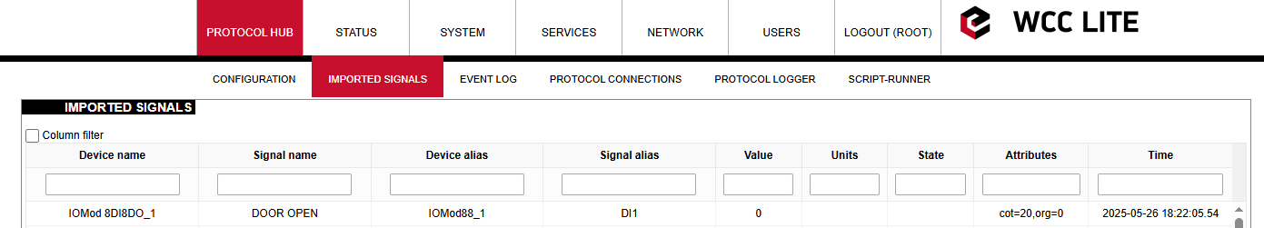
After the upload completes and no errors are detected, go to Protocol Hub --> Imported signals to verify that all signals have been successfully imported.
[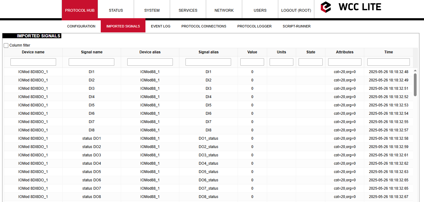](https://wiki.elseta.com/uploads/images/gallery/2025-05/image-1748261969330.png)
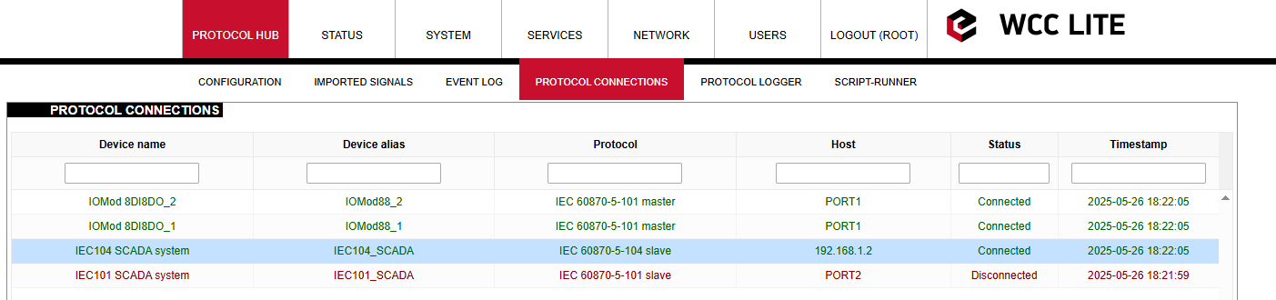
Before proceeding, check the protocol connections to confirm that both IOMOD 8DI8DO devices are connected to WCC Lite via PORT1. Open the Protocol Connections section to view all connected slave and master protocol devices.
[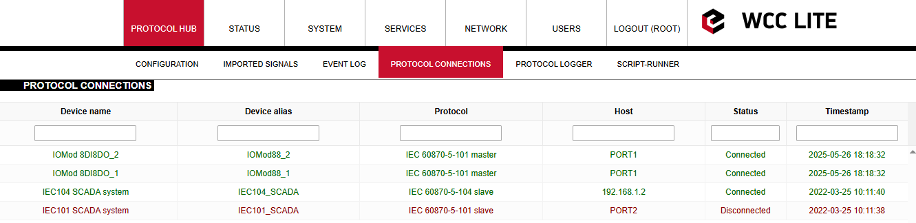](https://wiki.elseta.com/uploads/images/gallery/2025-05/image-1748261988953.png)
You can rename signal names according to your preferences.
[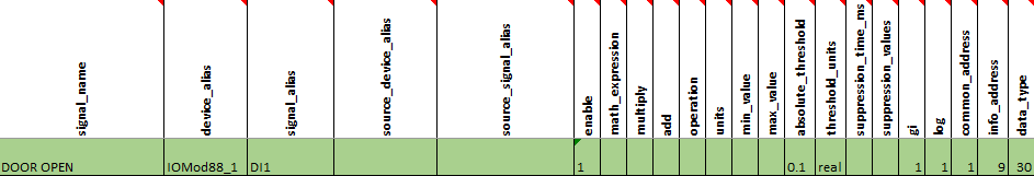](https://wiki.elseta.com/uploads/images/gallery/2025-05/image-1748262063541.png)
[](https://wiki.elseta.com/uploads/images/gallery/2025-05/image-1748263782202.png)
In every signals sheet, there is a signal named COMMUNICATION STATUS. This signal indicates whether the WCC Lite has established a connection with the device.
If everything is connected correctly and the service is running, the COMMUNICATION STATUS should display a value of 1. If not connected, it will display a value of 2.
[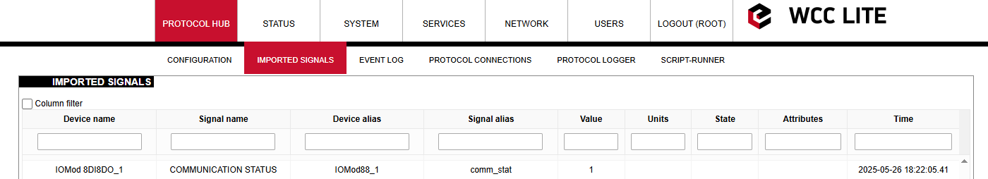](https://wiki.elseta.com/uploads/images/gallery/2025-05/image-1748264210950.png)
If the IOMOD needs to be connected to another port, you can change the configuration by updating the Device value in the Devices sheet from PORT1 to PORT2.
[](https://wiki.elseta.com/uploads/images/gallery/2025-05/image-1748267088069.png)
Please note that each port on the WCC Lite can only run a single protocol. Mixing different protocols on the same port is not supported. In addition, each device must have unique values for parameters such as ID, link address, and ASDU address.
### Simulating SCADA via Vinci software
After uploading the Excel configuration, you can simulate a SCADA connection using Vinci software. To simulate an IEC 104 slave, select the IEC 60870-5-104 protocol, choose Master (Client) mode, and press Start. In the Settings tab, make sure the Structure (COT, ASDU, and IOA size), Timeouts, and Windows values match those defined in the Excel configuration.
[](https://wiki.elseta.com/uploads/images/gallery/2025-03/image-1741958787156.png)
Set the correct IP address and port at the top of the Vinci window. The default IEC104 port is 2404. The IP address should match the IP of your WCC Lite device (by default, 192.168.1.1 if connected directly to your computer via Ethernet).
[](https://wiki.elseta.com/uploads/images/gallery/2022-12/image-1671616037090.png)
After clicking Start, open the Protocol Connections tab again to verify that the IEC104 slave is connected.
[](https://wiki.elseta.com/uploads/images/gallery/2025-05/image-1748264814531.png)
Once the IEC104 slave is connected, send a General Interrogation (GI) command. If everything is working correctly, the Statistics tab in Vinci should begin to display live data.
[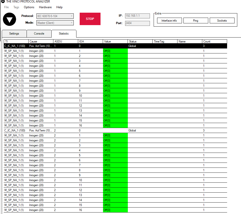](https://wiki.elseta.com/uploads/images/gallery/2025-05/image-1748264942085.png)
To test further, let's activate the first digital output (DO1) on both IOMODs. To do this, we will send a type 45 command (C\_SC\_NA\_1).
In the Excel configuration, under the sheet *Signals\_IEC104*, we specified that to activate the output on the first IOMOD, the command must be sent with the following parameters:
ASDU (common\_address) = 1, IOA (info\_address) = 101, type (data\_type) = 45.
For testing the second IOMOD, we assigned DO1 to IOA = 1001. The procedure remains the same—send a command with type = 45, this time using ASDU = 2, IOA = 1001.
# Protocol conversions
# Comlynx to Modbus TCP protocol conversion
## Description
This article describes WCC Lite configuration steps to enable Comlynx protocol conversion to Modbus TCP
[](https://wiki.elseta.com/uploads/images/gallery/2020-10/image-1601994154261.png)
## First steps
Before you begin, make sure you have completed all physical installation work according to the manufacturer's installation instructions.
Set up your computer and connect Ethernet cable to WCC Lite ETH0 port. Login with default credentials and setup basic required settings (name, network, users, etc. ). You can find configuration tutorials in [How to](https://wiki.elseta.com/books/how-to) articles.
After setup, download configuration template from device (Protocol Hub → Configuration → Template configuration Download)
Or download configuration example from this article [Files](#h_52402507611602751244400).
To prepare configuration fill information in both - [Devices](#bkmrk-configure-devices) and [Signals](#bkmrk-configure-signals) sheets:
## Configure devices
Add connected inverter with ComLynx protocol required information:
**name**
**device\_alias**
**enable**
**protocol**
**timeout\_ms**
**device**
**baudrate**
**databits**
**stopbits**
**parity**
**flowcontrol**
Inverter
Danfoss\_INV\_1
1
ComLynx
2000000
PORT1
19200
8
1
none
none
**scan\_rate\_ms**
**retry\_count**
**network**
**subnet**
**address**
60000
3
3
2
163
Add Modbus Slave required information:
**name**
**device\_alias**
**enable**
**protocol**
**timeout\_ms**
**bind\_address**
Modbus Slave
Modbus\_slave
1
Modbus TCP Slave
500000
0.0.0.0
**host**
**port**
**mode**
192.168.1.1
502
tcp
You can find more options and descriptions of the settings in [Device configuration](https://wiki.elseta.com/books/excel-configuration/page/device-configuration "Device configuration") article.
## Configure signals
Add connected inverter signals information. Use inverter manual for information and addresses (**tag\_job\_todo).**
**signal\_name**
**device\_alias**
**signal\_alias**
**enable**
**tag\_type**
**units**
**multiply**
**job\_todo**
**job\_todo**
**number\_type**
Total energy production
Danfoss\_INV\_1
Danfoss\_1
1
Normal
kWh
0,001
08|01|02
NA
UNSIGNED16
...
Where in **job\_todo** *08* is "module id", *01* - "Index", *02* - "SubIndex" of measurements.
**number\_type** can be found in manual as Data type id converted to data type as follow:
0x0: Not defined- Not supported
0x1: Boolean
0x2: Signed 8
0x3: Signed 16
0x4: Signed 32
0x5: Unsigned 8
0x6: Unsigned 16
0x7: Unsigned 32
0x8: Float
0x9: Visible string - Not supported
0xA: Packed bytes - Not supported
0xB: Packed words - Not supported
0xC - 0xF: Reserved- Not supported
Add Modbus slave signals information
**signal\_name**
**device\_alias**
**signal\_alias**
**source\_device\_alias**
**source\_signal\_alias**
**enable**
**tag\_type**
**units**
**multiply**
Total energy production
Modbus\_slave
Modbus\_1
Danfoss\_INV\_1
Danfoss\_1
1
Normal
kWh
1.0
**common\_address**
**function**
**info\_address**
**number\_type**
**size**
1
3
1
UNSIGNED16
1
Use measurements from inverter as a source to be forwarded.
You can find more options and descriptions of the settings in [Signals sheet](https://wiki.elseta.com/books/excel-configuration/page/signals-sheet "Signals sheet") article.
## Upload configuration
After configuring all devices and signals, follow these steps to check and upload configuration using WCC Excel Utility:
1. [Download ](https://wiki.elseta.com/books/wcclite-downloads/page/firmware-and-tools)and run WCC Excel Utility;
2. Select Excel file from your computer and click *Convert*;
3. Check if no events in red color occur. If so, edit Excel file according to event text and repeat Step 2;
4. Enter Host and credentials of WCC Lite and click *Upload configuration.*
Another method to upload the configuration is via the web interface:
1. Access the WCC Lite interface via your browser:
[](https://wiki.elseta.com/uploads/images/gallery/2024-12/image-1733135286847.png)
2. Upload the Excel configuration:
[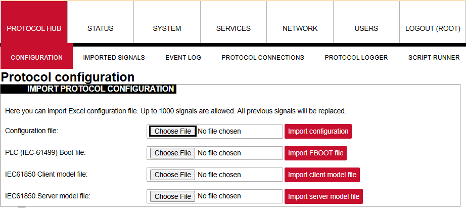](https://wiki.elseta.com/uploads/images/gallery/2024-12/image-1733135363443.png)
3. After a successful upload, the configuration will appear under the **DOWNLOAD CONFIGURATION** tab:
[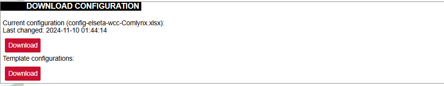](https://wiki.elseta.com/uploads/images/gallery/2024-12/image-1733135451404.png)
4. If any errors occur during the upload, follow the error messages, fix them along Excel utility guidelines.
## Files
1. Danfoss inverter manual - Accessing Inverter Parameters via RS485 using the ComLynx protocol [Download](https://wiki.elseta.com/attachments/4)
2. WCC Excel Utility [Download](https://wiki.elseta.com/books/wcclite-downloads/page/firmware-and-tools)
3. Example of configuration file [Download](https://wiki.elseta.com/attachments/629)
# DLMS Serial to IEC104 protocol conversion
## Description
The article describes WCC Lite configuration steps to enable DLMS Serial protocol conversion to IEC 60870-5-104.
[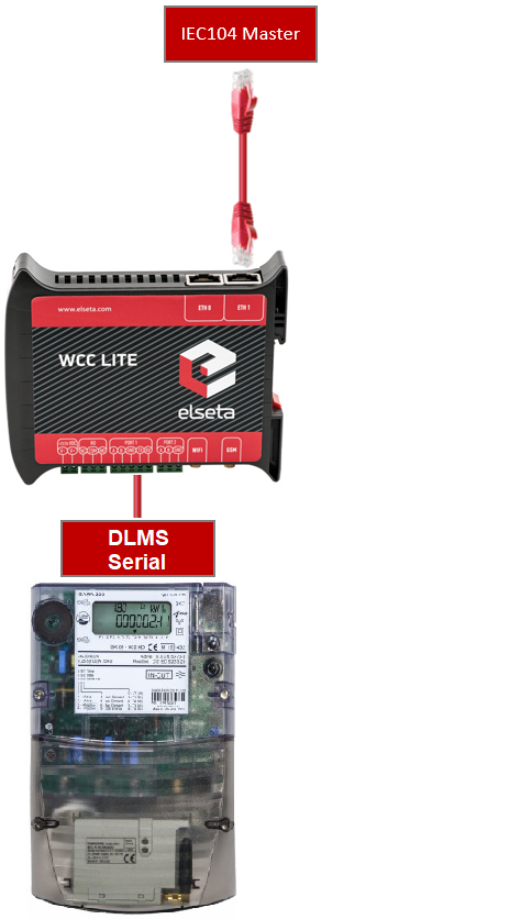](https://wiki.elseta.com/uploads/images/gallery/2023-05/image-1685538397956.png)
Fig 1.
## First steps
Before you begin, make sure you have completed all physical installation work according to the manufacturer's installation instructions.Set up your computer and connect Ethernet cable to WCC Lite ETH0 port. Login with default credentials and setup basic required settings (name, network, users, etc.). You can find configuration tutorials in [How to](https://wiki.elseta.com/books/how-to) articles.To prepare configuration fill information in both - [Devices ](https://wiki.elseta.com/books/how-to/page/dlms-serial-to-iec104-protocol-conversion#bkmrk-configure-devices)and [Signals](https://wiki.elseta.com/books/how-to/page/dlms-serial-to-iec104-protocol-conversion#bkmrk-configure-signals) sheets:
## Configure devices
##### Add connected Gama meter with **DLMS Serial** protocol required information:
**name**
**description**
**device\_alias**
**enable**
**protocol**
**serial\_number**
**device**
**databits**
**stopbits**
From Gama Meter
Elgama Gama 300
GAMA300
1
DLMS
2250259
PORT1
8
1
**baudrate**
**parity**
**flowcontrol**
**logical\_address**
**address\_size**
**client\_address**
**type**
4800
none
none
1
2
32
SN
**mode**
**auth**
DLMS-HDLC
LOW
More information concerning DLMS protocol configuration is provided in [DLMS/COSEM](https://wiki.elseta.com/books/manual-18/page/171-dlmscosem) article.
##### Add SCADA working on **IEC104** protocol required information:
**name**
**device\_alias**
**enable**
**protocol**
**bind\_address**
**host**
**port**
To SCADA
IEC104\_SCADA
1
IEC 60870-5-104 slave
0.0.0.0
192.168.1.10 192.168.71.1
2404
**asdu\_size**
**cot\_size**
**ioa\_size**
**rwt**
**swt**
**t1**
**t2**
**t3**
2
2
3
8
12
45
30
200
**time\_sync**
**message\_size**
**cache\_size**
1
249
100
More information concerning IEC104 protocol configuration is provided in [IEC 60870-5-104 Slave](https://wiki.elseta.com/books/manual-18/page/146-iec-60870-5-104-slave) article.
## Configure signals
Add connected meter measurements information.
**signal\_name**
**device\_alias**
**signal\_alias**
**obis\_job**
Voltage
GAMA300
L3\_U
1.0.72.7.0.255
Frequency
GAMA300
F
1.0.14.7.0.255
**obis\_job** - Objects are identified with the help of OBIS (Object Identification System) codes.
1. The first number of OBIS code defines the media (energy type) to which the metering is related. Nonmedia related information is handled as abstract data. For example both obis\_jobs in the table above starts with numbers 1 which stands for "Electricity related objects".
2. The second number defines the channel number, i.e. the number of the input of a metering equipment having several inputs for the measurement of energy of the same or different types (e.g. in data concentrators, registration units). Data from different sources can thus be identified. The definitions for this value group are independent from the value of the first number. In both obis\_jobs from the table above second number is set to zero which means that no channel is specified.
3. The third number defines the abstract or physical data items related to the information source concerned, for example current, voltage, power, volume, temperature. The definitions depend on the value of the first number. For example in obis\_jobs from the table above number 72 means voltage L3 and number 14 means frequency.
4. The forth number defines types, or the result of the processing of physical quantities identified with the numbers 1 and 3, according to various specific algorithms. The algorithms can deliver energy and demand quantities as well as other physical quantities. In both obis\_jobs from the table above forth number is set to 7 which stands for "Instantaneous value".
5. The value of the fifth number defines further processing or classification of quantities identified by numbers 1 to 4. In case of the first obis\_job number 0 means that all harmonics of the signal along with its fundamental frequency are going to be taken into consideration.
6. The value of the sixth number defines the storage of data, identified by numbers 1 to 5, according to different billing periods. Where this is not relevant, this value group can be used for further classification. In both obis\_jobs from the table above last number is set to 255 which means that data is not used.
Add **IEC104 Slave** signals information:
**signal\_name**
**device\_alias**
**signal\_alias**
**source\_device\_alias**
**source\_signal\_alias**
**enable**
IEC104 SCADA V
IEC104\_SCADA
IEC104\_SCADA\_V\_L3\_N
GAMA300
L3\_U
1
IEC104 SCADA F
IEC104\_SCADA
IEC104\_SCADA\_Freq
GAMA300
F
1
**log**
**gi**
**common\_address**
**info\_address**
**data\_type**
1
1
1
101
36
1
1
1
104
36
For more detailed DLMS protocol communication analysis Gurux DLMS Director application can be used.
## Upload configuration
After configuring all devices and signals, follow these steps to check and upload configuration using WCC Excel Utility:
1. [Download ](https://wiki.elseta.com/books/wcclite-downloads/page/firmware-and-tools)and run WCC Excel Utility;
2. Select Excel file from your computer and click *Convert*;
3. Check if no events in red color occur. If so, edit Excel file according to event text and repeat Step 2;
4. Enter Host and credentials of WCC Lite and click *Upload configuration.*
Another method to upload the configuration is via the web interface:
1. Access the WCC Lite interface via your browser:
[](https://wiki.elseta.com/uploads/images/gallery/2024-12/image-1733135286847.png)
2. Upload the Excel configuration:
[](https://wiki.elseta.com/uploads/images/gallery/2024-12/image-1733135363443.png)
3. After a successful upload, the configuration will appear under the **DOWNLOAD CONFIGURATION** tab:
[](https://wiki.elseta.com/uploads/images/gallery/2024-12/image-1733135451404.png)
4. If any errors occur during the upload, follow the error messages, fix them along Excel utility guidelines.
## Files
1. WCC Excel Utility [Download](https://wiki.elseta.com/books/wcclite-downloads/page/firmware-and-tools)
2. Example of configuration file [Download](https://wiki.elseta.com/attachments/104)
# DLMS TCP to DNP3 protocol conversion
## Setup
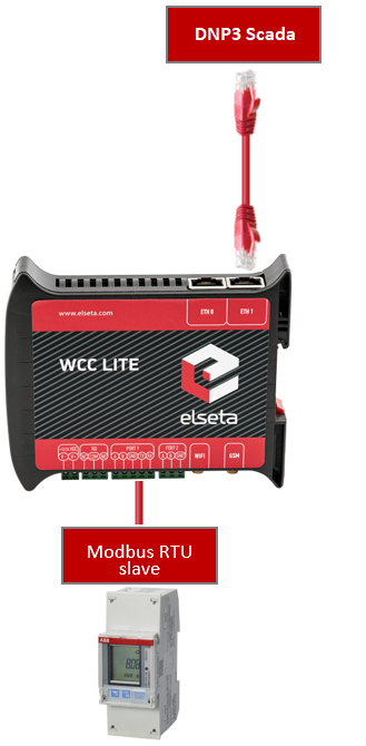
The article describes WCC Lite configuration steps to enable DLMS tcp protocol conversion to DNP3.
[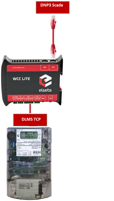](https://wiki.elseta.com/uploads/images/gallery/2023-07/image-1690294047661.png)
Fig 1. Connection scheme.
Before you begin, make sure you have completed all physical installation work according to the manufacturer's installation instructions.Set up your computer and connect the Ethernet cable to the WCC Lite ETH0 port. Log in with default credentials and set up basic required settings (name, network, users, etc.). You can find configuration tutorials in [How to](https://wiki.elseta.com/books/how-to) articles.To prepare the configuration, fill information in both the [Devices ](https://wiki.elseta.com/books/how-to/page/dlms-tcp-to-dnp3-protocol-conversion#bkmrk-configure-devices)and [Signals](https://wiki.elseta.com/books/how-to/page/dlms-tcp-to-dnp3-protocol-conversion#bkmrk-configure-signals) sheets:
## Configuring Devices
##### Add a connected Gama meter with the **DLMS TCP** protocol required information:
**name**
**description**
**device\_alias**
**enable**
**protocol**
**serial\_number**
**port**
From Gama Meter
Elgama Gama 300
GAMA300
1
DLMS
2393020
4059
**ip**
**logical\_address**
**address\_size**
**client\_address**
**type**
**mode**
**auth**
**password**
192.168.1.2
1
2
32
LN
DLMS-WRAPPER
LOW
00000002
More information concerning DLMS protocol configuration is provided in the [DLMS/COSEM](https://wiki.elseta.com/books/manual-18/page/171-dlmscosem) article.
##### Add the SCADA working on the **DNP3** protocol required information:
**name**
**device\_alias**
**enable**
**protocol**
**mode**
**host**
**bind\_address**
DNP3 SCADA system
DNP3\_SCADA
1
DNP3 TCP slave
TCP
192.168.1.215
0.0.0.0
**port**
destination\_address
source\_address
unsol\_classes
20000
10
1
1,2,3
More information concerning DNP3 protocol configuration is provided in the [DNP 3.0 Slave](https://wiki.elseta.com/books/manual-18/page/123-dnp-30-slave) article.
## Configuring Signals
Add connected meter measurements information.
**signal\_name**
**device\_alias**
**signal\_alias**
**obis\_job**
Voltage L3-N
GAMA300
L3\_U
1.0.72.7.0.255
Frequency
GAMA300
F
1.0.14.7.0.255
Current L3
GAMA300
L3-I
1.0.71.7.0.255
Absolute active instantaneous power
GAMA300
P
1.0.15.7.0.255
**Obis\_job** - Objects are identified with the help of OBIS (Object Identification System) codes.
1. The first number of the OBIS code defines the media (energy type) to which the metering is related. Non-media-related information is handled as abstract data. For example, both obis\_jobs in the table above start with number 1, which stands for "Electricity related objects".
2. The second number defines the channel number, i.e. the number of the input of a metering equipment having several inputs for the measurement of energy of the same or different types (e.g. in data concentrators, registration units). Data from different sources can thus be identified. The definitions for this value group are independent of the value of the first number. In both obis\_jobs from the table above second number is set to zero, which means that no channel is specified.
3. The third number defines the abstract or physical data items related to the information source concerned, for example, current, voltage, power, volume, temperature. The definitions depend on the value of the first number. For example, in obis\_jobs from the table above, the number 72 means voltage L3, and the number 14 means frequency.
4. The fourth number defines types, or the result of the processing of physical quantities identified with the numbers 1 and 3, according to various specific algorithms. The algorithms can deliver energy and demand quantities as well as other physical quantities. In both obis\_jobs from the table above fourth number is set to 7, which stands for "Instantaneous value".
5. The value of the fifth number defines further processing or classification of quantities identified by numbers 1 to 4. In case of the first obis\_job number 0 means that all harmonics of the signal along with its fundamental frequency are going to be taken into consideration.
6. The value of the sixth number defines the storage of data, identified by numbers 1 to 5, according to different billing periods. Where this is not relevant, this value group can be used for further classification. In both obis\_jobs from the table above last number is set to 255, which means that the data is not used.
Add **DNP3 Slave** signals information:
**signal\_name**
**device\_alias**
**signal\_alias**
**source\_device\_alias**
**source\_signal\_alias**
**enable**
DNP3 SCADA V
DNP3\_SCADA
DNP3\_SCADA\_V\_L3\_N
GAMA300
L3\_U
1
DNP3 SCADA F
DNP3\_SCADA
DNP3\_SCADA\_Freq
GAMA300
F
1
DNP3 SCADA A
DNP3\_SCADA
DNP3\_SCADA\_A\_L3
GAMA300
L3\_I
1
DNP3 SCADA KW
DNP3\_SCADA
DNP3\_SCADA\_P
GAMA300
P
1
**index**
**signal\_type**
**static\_variation**
**event\_variation**
**class\_num**
1
analog
1
3
2
2
analog
1
3
2
3
analog
1
3
2
4
analog
1
3
2
For more detailed DLMS protocol communication analysis Gurux DLMS Director application can be used.
## Uploading the Configuration
After configuring all devices and signals, follow these steps to check and upload the configuration using the WCC Excel Utility:
1. [Download ](https://wiki.elseta.com/books/wcclite-downloads/page/firmware-and-tools)and run WCC Excel Utility.
2. Select the firmware version from the drop-down menu.
3. Select the Excel file from your computer and click *Convert*.
4. Check if no events in red color occur. If so, edit the Excel file according to the event text and repeat Step 2.
5. Enter the Host and credentials of WCC Lite, click connect and then *Upload configuration.*
[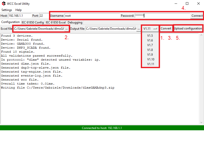](https://wiki.elseta.com/uploads/images/gallery/2025-04/image-1744036903331.png)
Another method to upload the configuration is via the web interface:
1. Access the WCC Lite interface via your browser. The default IP address is 192.168.1.1. Enter credentials:
[](https://wiki.elseta.com/uploads/images/gallery/2024-12/image-1733135286847.png)
2. Upload the Excel configuration:
[](https://wiki.elseta.com/uploads/images/gallery/2024-12/image-1733135363443.png)
3. After a successful upload, the configuration will appear under the **DOWNLOAD CONFIGURATION** tab:
[](https://wiki.elseta.com/uploads/images/gallery/2024-12/image-1733135451404.png)
4. If any errors occur during the upload, follow the error messages, fix them according to Excel utility guidelines.
## Files
1. WCC Excel Utility [Download](https://wiki.elseta.com/attachments/655)
2. Example of configuration file [Download](https://wiki.elseta.com/attachments/656)
# Modbus RTU to IEC104 protocol conversion
## Setup
This article describes WCC Lite configuration steps to enable Modbus TCP protocol conversion to IEC 104.
[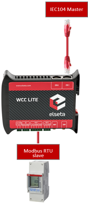](https://wiki.elseta.com/uploads/images/gallery/2020-10/image-1602846671040.png)
Before you begin, make sure you have completed all physical installation work according to the manufacturer's installation instructions.
Set up your computer and connect the Ethernet cable to the WCC Lite ETH0 port. Log in with default credentials and set up basic required settings (name, network, users, etc. ). You can find configuration tutorials in [How to](https://wiki.elseta.com/books/how-to) articles.
After setup, download the configuration template from the device (Protocol Hub → Configuration → Template configuration Download)
Or download the configuration example from this article.
To prepare the configuration, fill in the information in both the [Devices ](#bkmrk-configure-devices)and [Signals](#bkmrk-configure-signals) sheets:
## Configuring Devices
##### Add a connected ABB meter with the Modbus RTU protocol required information:
**name**
**description**
**device\_alias**
**enable**
**protocol**
**id**
**device**
**baudrate**
**databits**
From ABB Meter
ABB B21
B21
1
Modbus RTU
1
PORT2
9600
8
**stopbits**
**parity**
**flowcontrol**
**scan\_rate\_ms**
**serial\_delay**
**retry\_count**
1
none
none
5000
200
3
##### Add SCADA working on IEC104 protocol required information:
**name**
**description**
**device\_alias**
**enable**
**protocol**
**bind\_address**
**host**
**port**
To SCADA
iec104
1
IEC 60870-5-104 slave
0.0.0.0
192.168.1.10 192.168.71.1
2404
**asdu\_size**
**cot\_size**
**ioa\_size**
**rwt**
**swt**
**t1**
**t2**
**t3**
**time\_sync**
**message\_size**
**cache\_size**
2
2
3
8
12
45
30
200
1
249
100
You can find more options and descriptions of the settings in the [Device configuration](https://wiki.elseta.com/books/excel-configuration/page/device-configuration "Device configuration") article.
## Configuring Signals
Add connected meter measurements information. Use the meter manual for information and addresses (**tag\_job\_todo).**
**signal\_name**
**device\_alias**
**signal\_alias**
**enable**
**multiply**
**log**
**job\_todo**
**tag\_job\_todo**
**number\_type**
Voltage
B21
U
1
0.1
1
3;23296;2
3;23296;2
UNSIGNED32
Current
B21
I
1
0.01
1
3;23308;2
3;23308;2
UNSIGNED32
Active power
B21
P
1
0.00001
1
3;23316;2
3;23316;2
SIGNED32
Frequency
B21
F
1
0.01
1
3;23340;1
3;23340;1
UNSIGNED16
Power factor
B21
Cos
1
0.001
1
3;23354;1
3;23354;1
SIGNED16
Active import
B21
E
1
0.01
1
3;20480;4
3;20480;4
FLOAT
**job\_todo** -Request to send according to Modbus specification without device address and checksum;
**tag\_job\_todo** - a subset of the **job\_todo** field, exact address of measurement (tag)
Add **IEC104** master signals information:
**signal\_name**
**device\_alias**
**signal\_alias**
**source\_device\_alias**
**source\_signal\_alias**
Voltage
iec104
tag-iec104-1001
B21
U
Current
iec104
tag-iec104-1002
B21
I
Active power
iec104
tag-iec104-1003
B21
P
Frequency
iec104
tag-iec104-1004
B21
F
Power factor
iec104
tag-iec104-1005
B21
Cos
Active import
iec104
tag-iec104-1006
B21
E
**enable**
**log**
**units**
**multiply**
**gi**
**common\_address**
**info\_address**
**data\_type**
1
1
V
1.0
1
1
1001
13
1
1
A
1.0
1
1
1002
13
1
1
kW
1.0
1
1
1003
13
1
1
Hz
1.0
1
1
1004
13
1
1
1.0
1
1
1005
13
1
1
kWh
1.0
1
1
1006
13
## Other examples with the Rail350 meter
The video covers only 1.5 firmware version.
## Uploading the Configuration
After configuring all devices and signals, follow these steps to check and upload the configuration using the WCC Excel Utility:
1. [Download ](https://wiki.elseta.com/books/wcclite-downloads/page/firmware-and-tools)and run WCC Excel Utility.
2. Select the firmware version from the drop-down menu.
3. Select the Excel file from your computer and click *Convert*.
4. Check if no events in red color occur. If so, edit the Excel file according to the event text and repeat Step 2.
5. Enter the Host and credentials of WCC Lite, click connect and then *Upload configuration.*
[](https://wiki.elseta.com/uploads/images/gallery/2025-04/image-1744036903331.png)
Another method to upload the configuration is via the web interface:
1. Access the WCC Lite interface via your browser. The default IP address is 192.168.1.1. Enter credentials:
[](https://wiki.elseta.com/uploads/images/gallery/2024-12/image-1733135286847.png)
2. Upload the Excel configuration:
[](https://wiki.elseta.com/uploads/images/gallery/2024-12/image-1733135363443.png)
3. After a successful upload, the configuration will appear under the **DOWNLOAD CONFIGURATION** tab:
[](https://wiki.elseta.com/uploads/images/gallery/2024-12/image-1733135451404.png)
4. If any errors occur during the upload, follow the error messages, fix them according to Excel utility guidelines.
## Files
1. ABB meter manual [Download](https://search.abb.com/library/Download.aspx?DocumentID=2CMC485004M0201&LanguageCode=en&DocumentPartId=&Action=Launch)
2. WCC Excel Utility [Download](https://wiki.elseta.com/attachments/657)
3. Example of configuration file [Download](https://wiki.elseta.com/attachments/658)
# Modbus RTU to DNP3 protocol conversion
## Setup
The article describes WCC Lite configuration steps to enable Modbus RTU protocol conversion to DNP3 serial.
[](https://wiki.elseta.com/uploads/images/gallery/2025-04/image-1744184546840.png)
Before you begin, make sure you have completed all physical installation work according to the manufacturer's installation instructions.Set up your computer and connect the Ethernet cable to the WCC Lite ETH0 port. Log in with default credentials and set up basic required settings (name, network, users, etc.). You can find configuration tutorials in [How to](https://wiki.elseta.com/books/how-to) articles.To prepare the configuration, fill in the information in both the [Devices ](https://wiki.elseta.com/books/how-to/page/dlms-serial-to-iec104-protocol-conversion#bkmrk-configure-devices)and [Signals](https://wiki.elseta.com/books/how-to/page/dlms-serial-to-iec104-protocol-conversion#bkmrk-configure-signals) sheets:
## Configuring Devices
##### Add a connected ABB meter with the Modbus RTU protocol required information:
**name**
**description**
**device\_alias**
**enable**
**protocol**
**id**
**device**
**baudrate**
**databits**
From ABB Meter
ABB B21
B21
1
Modbus RTU
1
PORT1
9600
8
**stopbits**
**parity**
**flowcontrol**
**scan\_rate\_ms**
**serial\_delay**
**retry\_count**
1
none
none
5000
200
3
##### Add the SCADA working on the DNP3 protocol required information:
**name**
**device\_alias**
**enable**
**protocol**
**mode**
**bind\_address**
DNP3
DNP3\_SCADA
1
DNP3 TCP slave
TCP
0.0.0.0
**host**
**port**
source\_address
unsol\_classes
192.168.1.1
20000
1
1,2,3
You can find more options and descriptions of the settings in the [Device configuration](https://wiki.elseta.com/books/excel-configuration/page/device-configuration "Device configuration") article.
## Configuring Signals
Add connected meter measurements information. Use the meter manual for information and addresses (**tag\_job\_todo).**
**signal\_name**
**device\_alias**
**signal\_alias**
**enable**
**multiply**
**log**
**job\_todo**
**tag\_job\_todo**
**number\_type**
Voltage
B21
U
1
0.1
1
3;23296;2
3;23296;2
UNSIGNED32
Current
B21
I
1
0.01
1
3;23308;2
3;23308;2
UNSIGNED32
Active power
B21
P
1
0.00001
1
3;23316;2
3;23316;2
SIGNED32
Frequency
B21
F
1
0.01
1
3;23340;1
3;23340;1
UNSIGNED16
Power factor
B21
Cos
1
0.001
1
3;23354;1
3;23354;1
SIGNED16
Active import
B21
E
1
0.01
1
3;20480;4
3;20480;4
FLOAT
**job\_todo** -Request to send according to Modbus specification without device address and checksum;
**tag\_job\_todo** - a subset of the **job\_todo** field, exact address of measurement (tag)
Add **DNP3** master signals information:
**signal\_name**
**device\_alias**
**signal\_alias**
**source\_device\_alias**
**source\_signal\_alias**
Voltage
dnp3
dnp3\_1001
B21
U
Current
dnp3
dnp3\_1002
B21
I
Active power
dnp3
dnp3\_1003
B21
P
Frequency
dnp3
dnp3\_1004
B21
F
Power factor
dnp3
dnp3\_1005
B21
Cos
Active import
dnp3
dnp3\_1006
B21
E
**enable**
**log**
**index**
**signal\_type**
**static\_variation**
**event\_variation**
**class\_num**
1
1
1
analog
1
1
13
1
1
2
analog
1
1
13
1
1
3
analog
1
1
13
1
1
4
analog
1
1
13
1
1
5
analog
1
1
13
1
1
6
analog
1
1
13
## Uploading the Configuration
After configuring all devices and signals, follow these steps to check and upload the configuration using the WCC Excel Utility:
1. [Download ](https://wiki.elseta.com/books/wcclite-downloads/page/firmware-and-tools)and run WCC Excel Utility.
2. Select the firmware version from the drop-down menu.
3. Select the Excel file from your computer and click *Convert*.
4. Check if no events in red colour occur. If so, edit the Excel file according to the event text and repeat Step 2.
5. Enter the Host and credentials of WCC Lite, click connect and then *Upload configuration.*
[](https://wiki.elseta.com/uploads/images/gallery/2025-04/image-1744036903331.png)
Another method to upload the configuration is via the web interface:
1. Access the WCC Lite interface via your browser. The default IP address is 192.168.1.1. Enter credentials:
[](https://wiki.elseta.com/uploads/images/gallery/2024-12/image-1733135286847.png)
2. Upload the Excel configuration:
[](https://wiki.elseta.com/uploads/images/gallery/2024-12/image-1733135363443.png)
3. After a successful upload, the configuration will appear under the **DOWNLOAD CONFIGURATION** tab:
[](https://wiki.elseta.com/uploads/images/gallery/2024-12/image-1733135451404.png)
4. If any errors occur during the upload, follow the error messages and fix them according to Excel utility guidelines.
## Files
1. WCC Excel Utility [Download](https://wiki.elseta.com/attachments/660)
2. Example configuration file [Download](https://wiki.elseta.com/attachments/661)
3. ABB meter manual [Download](https://wiki.elseta.com/attachments/662)
# DLMS Serial to IEC61850-server protocol conversion (Wcc Lite FW: 1.7.0)
## Description
The article describes WCC Lite configuration steps to enable DLMS Serial protocol conversion to IEC 61850-server.
[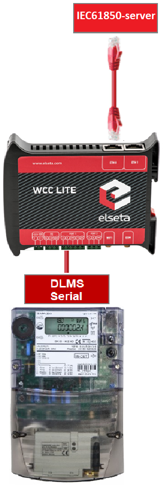](https://wiki.elseta.com/uploads/images/gallery/2023-07/image-1690356504117.png)
Fig 1. Connecting Meter with DLMS serial protocol to Wcc Lite and IEC61850 server
## First steps
Before you begin, make sure you have completed all physical installation work according to the manufacturer's installation instructions.Set up your computer and connect Ethernet cable to WCC Lite ETH0 port. Login with default credentials and setup basic required settings (name, network, users, etc.). You can find configuration tutorials in [How to](https://wiki.elseta.com/books/how-to) articles.To prepare configuration fill information in both - [Devices ](https://wiki.elseta.com/books/how-to/page/dlms-serial-to-iec104-protocol-conversion#bkmrk-configure-devices)and [Signals](https://wiki.elseta.com/books/how-to/page/dlms-serial-to-iec104-protocol-conversion#bkmrk-configure-signals) sheets:
## Configure devices (excel "Devices" sheet)
##### Add required information for connected Gama meter with **DLMS Serial** protocol:
**name**
**description**
**device\_alias**
**protocol**
**serial\_number**
**device**
**databits**
**stopbits**
**baudrate**
**parity**
DLMS Serial
DLMS Serial
DLMS\_Meter
DLMS
2250259
PORT1
8
1
4800
none
**flowcontrol**
**enable**
**auth**
**logical\_address**
**address\_size**
**client\_address**
**type**
**mode**
none
1
LOW
1
2
32
SN
DLMS-HDLC
More information concerning DLMS protocol configuration is provided in [DLMS/COSEM](https://wiki.elseta.com/books/manual-18/page/171-dlmscosem) article.
#####
##### Add **IEC 61850 server** protocol required information:
**name**
**description**
**device\_alias**
**protocol**
**bind\_address**
IEC 61850 Server
IEC 61850 Server
iec\_61850\_server
iec 61850 server
0.0.0.0
**ied\_name**
**access\_point**
**port**
**auth**
**host**
**model\_filename**
WCCLITE
LD0
102
NONE
192.168.1.2
WCC
More information concerning IEC 61850 server protocol configuration is provided in [IEC 61850 server](https://wiki.elseta.com/books/manual-18/page/152-iec-61850-server) article.
## Configure signals (Excel "Signals" sheet)
The signals for all devices can be separated to different excel sheets for different device or listed in one excel sheet. In this case signals will be separated to **SignalsDLMS** and **SignalsIEC61850** excel sheets. Make sure that these excel sheet names for different device signals always must start with word **Signals.** The example template for this case is added at the end of this article.
#### Add signals information for connected meter with DLMS Serial protocol
(Excel **SignalsDLMS** sheet):
**signal\_name**
**device\_alias**
**signal\_alias**
**obis\_job**
Voltage L1-N
DLMS\_Meter
Voltage\_L1-N
1.0.32.7.0.255
Voltage L2-N
DLMS\_Meter
Voltage\_L2-N
1.0.52.7.0.255
Voltage L3-N
DLMS\_Meter
Voltage\_L3-N
1.0.72.7.0.255
Frequency
DLMS\_Meter
Frequency
1.0.14.7.0.255
Current L3
DLMS\_Meter
Current\_L3
1.0.71.7.0.255
**obis\_job** - Objects are identified with the help of OBIS (Object Identification System) codes.
1. The first number of OBIS code defines the media (energy type) to which the metering is related. Nonmedia
related information is handled as abstract data. For example all obis\_jobs in the table above starts with numbers 1 which stands for "Electricity related objects".
2. The second number defines the channel number, i.e. the number of the input of a metering
equipment having several inputs for the measurement of energy of the same or different types
(e.g. in data concentrators, registration units). Data from different sources can thus be
identified. The definitions for this value group are independent from the value of the first number. In all obis\_jobs from the table above second number is set to zero which means that no channel is specified.
3. The third number defines the abstract or physical data items related to the information
source concerned, for example current, voltage, power, volume, temperature. The definitions
depend on the value of the first number. For example in obis\_jobs from the table above number 72 means voltage L3 and number 14 means frequency.
4. The forth number defines types, or the result of the processing of physical quantities
identified with the numbers 1 and 3, according to various specific algorithms. The
algorithms can deliver energy and demand quantities as well as other physical quantities. In all obis\_jobs from the table above forth number is set to 7 which stands for "Instantaneous value".
5. The value of the fifth number defines further processing or classification of quantities identified by numbers 1 to 4. In case of the first obis\_job number 0 means that all harmonics of the signal along with its fundamental frequency are going to be taken into consideration.
6. The value of the sixth number defines the storage of data, identified by numbers 1 to 5, according to
different billing periods. Where this is not relevant, this value group can be used for further
classification. In all obis\_jobs from the table above last number is set to 255 which means that data is not used.
#### Add signals information for **IEC 61850 server** (Excel **SignalsIEC61850** sheet):
**signal\_name**
**device\_alias**
**signal\_alias**
**source\_device\_alias**
**source\_signal\_alias**
LD0\_\_GGIO\_5\_AnIn1\_mag.f
iec\_61850\_server
LD0\_\_GGIO\_5\_AnIn1\_mag.f
DLMS\_Meter
Voltage\_L1-N
LD0\_\_GGIO\_5\_AnIn2\_mag.f
iec\_61850\_server
LD0\_\_GGIO\_5\_AnIn2\_mag.f
DLMS\_Meter
Voltage\_L2-N
LD0\_\_GGIO\_5\_AnIn3\_mag.f
iec\_61850\_server
LD0\_\_GGIO\_5\_AnIn3\_mag.f
DLMS\_Meter
Voltage\_L3-N
LD0\_\_GGIO\_5\_AnIn4\_mag.f
iec\_61850\_server
LD0\_\_GGIO\_5\_AnIn4\_mag.f
DLMS\_Meter
Frequency
LD0\_\_GGIO\_5\_AnIn5\_mag.f
iec\_61850\_server
LD0\_\_GGIO\_5\_AnIn5\_mag.f
DLMS\_Meter
Current\_L3
**ld\_instance**
**ln\_class**
**ln\_instance**
**cdc**
**data\_object**
**da\_fc**
**number\_type**
**da\_value**
**Log**
LD0
GGIO
5
MV
AnIn1
MX
FLOAT32
mag.f
1
LD0
GGIO
5
MV
AnIn2
MX
FLOAT32
mag.f
1
LD0
GGIO
5
MV
AnIn3
MX
FLOAT32
mag.f
1
LD0
GGIO
5
MV
AnIn4
MX
FLOAT32
mag.f
1
LD0
GGIO
5
MV
AnIn5
MX
FLOAT32
mag.f
1
From the table above it can be seen that IEC 61850 server signals has **source\_device\_alias** and **source\_signal\_alias** in which device\_alias and signal\_alias of DLMS meter signals are described. That is how DLMS meter signals are linked to IEC61850 server signals, so the measurements of the DLMS meter could be transported to IEC 61850 server.
For more detailed DLMS protocol communication analysis Gurux DLMS Director application can be used.
## ICD file for IEC 61850 server
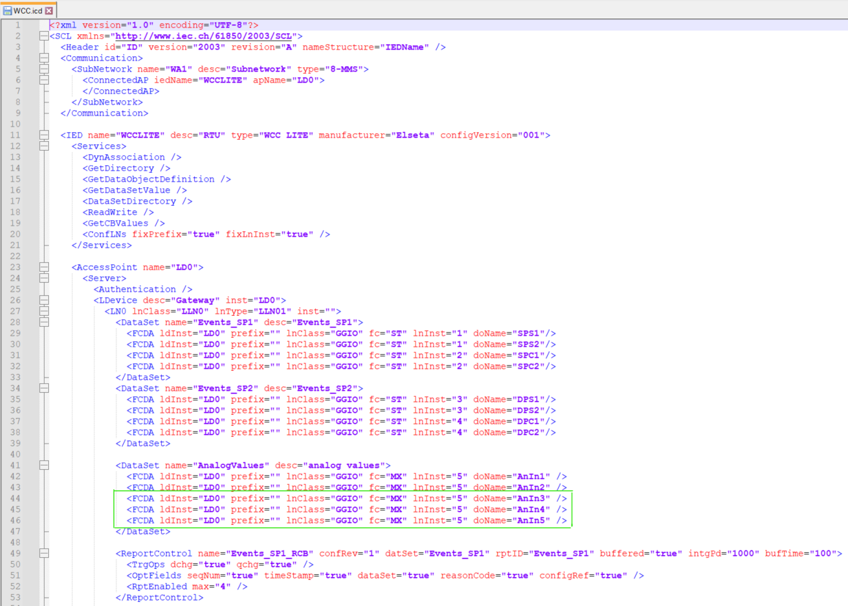
IED Capability Description (ICD) files are a specific type of Substation Configuration Language (SCL) file, containing a generic description of the whole capability range of a given device, including the functions and objects it can support. These ICD files can be found on internet, edited and adapted for current project. In this case the ICD file with 2 analog signals was edited, so it could have 5 analog signals for DLMS measurements. For that purpose, 3 additional signals was described in ICD file, so 5 analog signals could be linked with signals from DLMS. The ICD file and added signals are shown in Fig. 2. If it is needed to have more analog or other type of signals, the ICD file must be analyzed and signals added to the correct place of the file.
[](https://wiki.elseta.com/uploads/images/gallery/2023-07/image-1690292826983.png)[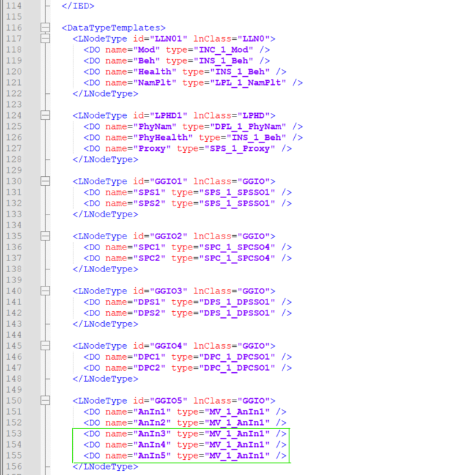](https://wiki.elseta.com/uploads/images/gallery/2023-07/image-1690292954514.png)
Fig. 2 Editing the ICD file
This ICD file will be used for creating the IEC 61850 server model file, which later will be uploaded to Wcc Lite. Also the ICD file will be uploaded to IEDscout app, for simulating the client. Other apps for simulation of client can be used as well.
## Generating Server Model file for Wcc Lite
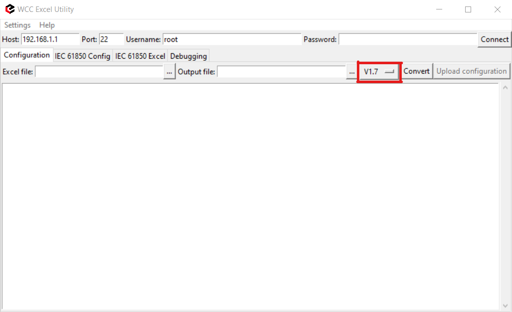
For this step, Wcc Excel Utility app will be used. Firstly open Wcc Excel Utility app and choose **version 1.7** in "Configuration" tab**.**
[](https://wiki.elseta.com/uploads/images/gallery/2023-07/image-1690294044910.png)
Fig. 3 Choosing the right version
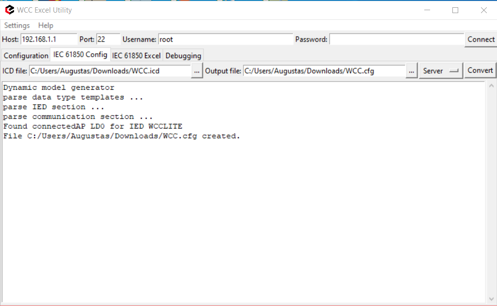
Second step is to go to IEC61850 Config tab, choose the ICD file that is needed and Output file directory of Server Model file. The name of output file should be the same as the name specified in the Excel configuration "Devices" tab "**model\_filename**" for IEC 61850 server. The extension of Server Model file using **Wcc Lite 1.7.0** firmware should be **.cfg** but using newer version of Wcc Excel Utility the extension **.server** can be created by default. This can be changed by editing the Server Model file name. Now "convert" button needs to be pressed and the Server Model file will be generated (Fig. 4). After that, this Server Model file needs to be uploaded to Wcc Lite WEB (Fig. 5).
[](https://wiki.elseta.com/uploads/images/gallery/2023-07/image-1690295167581.png)
Fig. 4 Generating Server Model file
[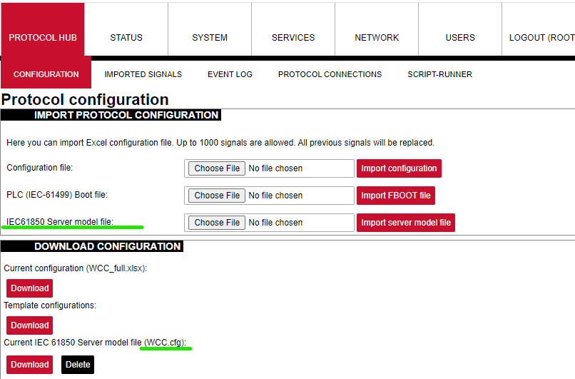](https://wiki.elseta.com/uploads/images/gallery/2023-07/image-1690295297098.png)
Fig. 5 Uploading IEC 61850 Server Model file to Wcc Lite WEB
### Uploading Wcc Lite configuration
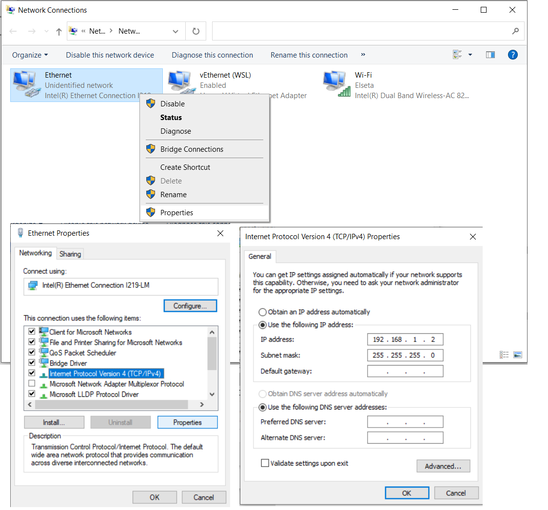
After the Server Model file is uploaded, and made sure that Server Model file name matches the one specified in excel configuration we are now able to upload excel configuration to Wcc Lite. One more thing to notice, in Excel configuration "Devices" sheet "host" parameter for IEC61850 server is 192.168.1.2. This IP should match the PC Ethernet IP, to which Wcc Lite ETH0 port is connected via ETH cable and can be set manually. This is shown in Fig. 6.
[](https://wiki.elseta.com/uploads/images/gallery/2023-07/image-1690357201276.png)
Fig. 6 Changing PC IP (TCP/IPv4) to match the Host IP in configuration
When all parameter described earlier matches the ones specified in configuration, we can upload the configuration to Wcc Lite WEB. It is shown in Fig. 7. Simply choose the Excel configuration and press "import configuration". The upload may take several minutes.
[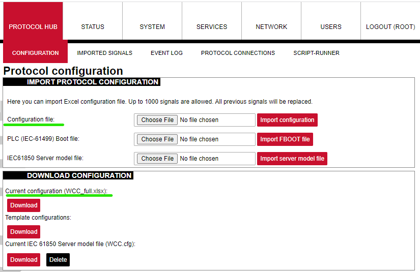](https://wiki.elseta.com/uploads/images/gallery/2023-07/image-1690357767962.png)
Fig. 7 Uploading Excel configuration to Wcc Lite.
## Starting IEC 61850 server
Now, when needed files were uploaded to Wcc Lite, we can start IEC61850 server. For this step the debugger interface will be needed. We prefer using terminal window with installed linux subsystem or other debugger interfaces like PuTTY app. These apps can be found and downloaded on the internet. Firstly we need to connect to Wcc Lite through SSH (using PuTTY, SSH connection type should be chosen and Wcc Lite IP 192.168.1.1 entered). Following commands should be entered in the debugger window:
1\. Connecting to Wcc Lite: **ssh root@192.168.1.1**
2\. Login: **root** Password: **your Wcc Lite pasword**
3\. Stopping the IEC 61850 service: **/etc/init.d/iec61850-server stop**
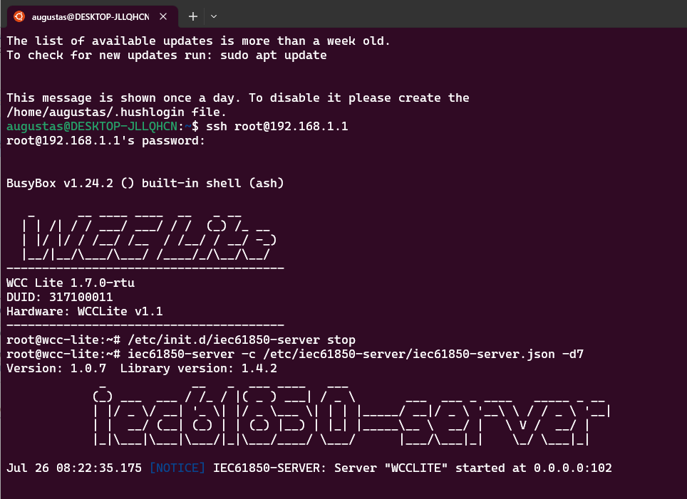
4\. Starting IEC61850 server in debugger mode: **iec61850-server -c /etc/iec61850-server/iec61850-server.json -d7**
After these commands are executed, the IEC 61850 server is started, it is shown in Fig. 8.
[](https://wiki.elseta.com/uploads/images/gallery/2023-07/image-1690359835315.png)
Fig. 8 Connecting to Wcc Lite through SSH and starting IEC61850 server
## Connecting to Wcc Lite (server) on IEDscout (client)
For this step, IEDscout will be needed. IEDScout is an ideal tool for protection and substation automation engineers working with IEC 61850 devices. It provides access to the IEDs (Intelligent Electronic Devices) and performs numerous useful functions when working with them. The software can simulate entire Ed. Also any different but similar functionality software can be used as well. Following steps are done using IEDscout software.
1\. Open IEDscout software, then choose and open ICD file that is needed.
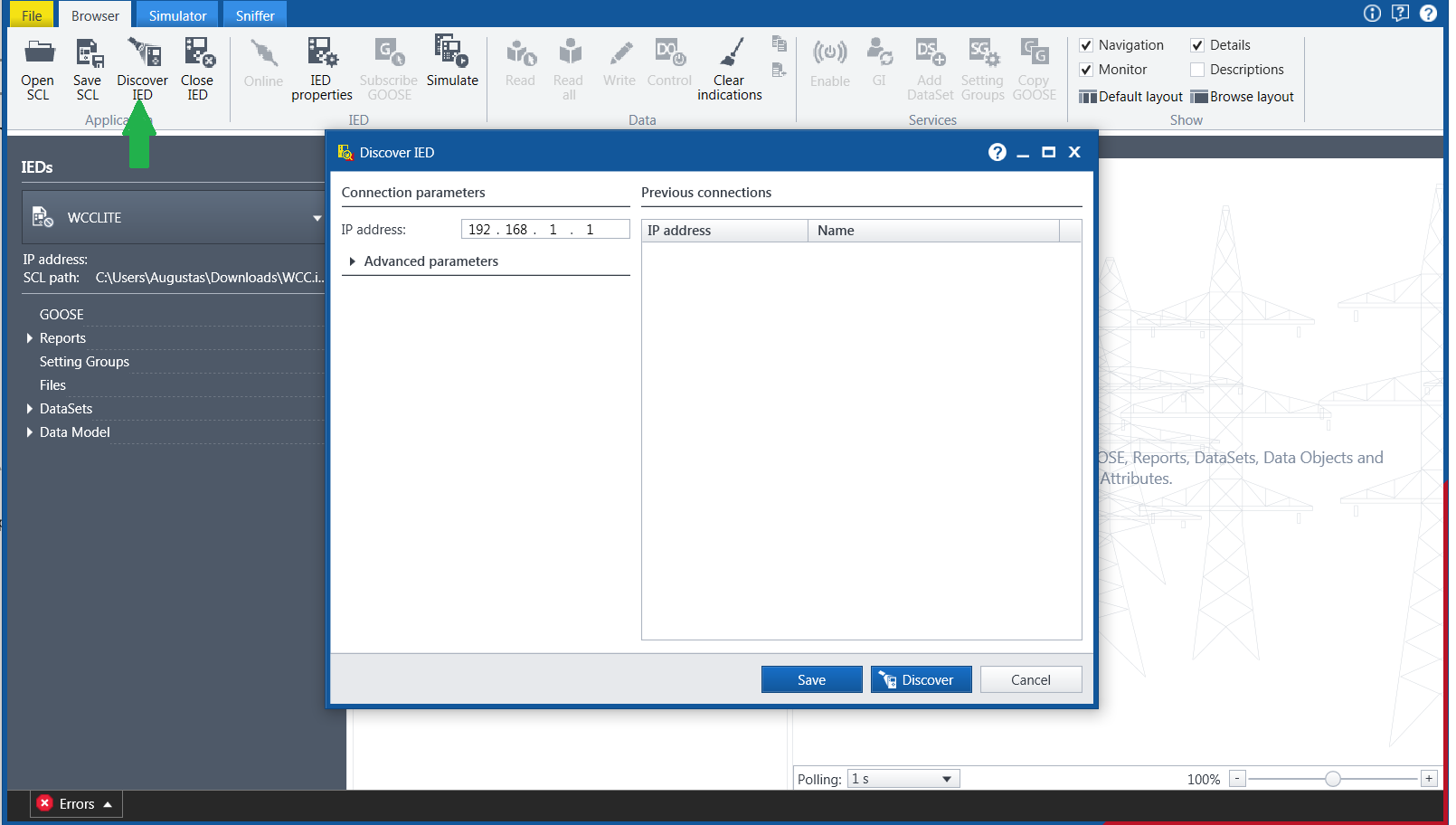
2\. In opened IEDscout Browser window click "Discover IED", then in opened window enter Wcc Lite IP (192.168.1.1) and press "discover" (Fig. 9).
3\. If the Wcc Lite did not connect when "discover" was pressed, then it is needed to press "Online". The indication, that IEC61850 server and Meter with DLMS serial protocol are connected correctly can be seen in Wcc Lite WEB "protocol connections" tab (Fig. 10).
Now Wcc Lite IEC61850 server and IEC61850 client on IEDscout are connected and after few moments we should see measurement from the Meter in the debugger window. When measurements from the Meter appears in debugger window (Fig. 11), press "Read" on IEDscout to update values (Fig. 12).
All these measurements are also represented in Wcc Lite WEB. There you can see that it has DLMS serial Meter signals and IEC 61850 server signals all in one place in "Imported signals" tab (Fig. 13).
[](https://wiki.elseta.com/uploads/images/gallery/2023-07/image-1690360585596.png)
Fig. 9 Starting IED on IEDscout
[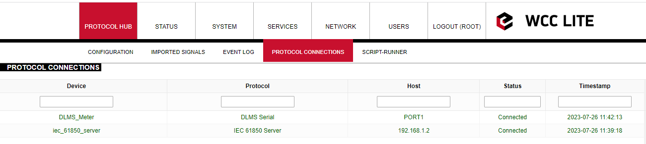](https://wiki.elseta.com/uploads/images/gallery/2023-07/image-1690361170192.png)
Fig. 10 Protocol connections
[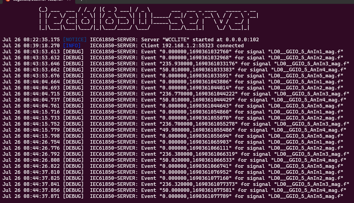](https://wiki.elseta.com/uploads/images/gallery/2023-07/image-1690361780503.png)
Fig. 11 Measurements from Meter linked to IEC61850 server signals
[](https://wiki.elseta.com/uploads/images/gallery/2023-07/image-1690361918281.png)
Fig. 12 Measurements appeared in IEDscout software
[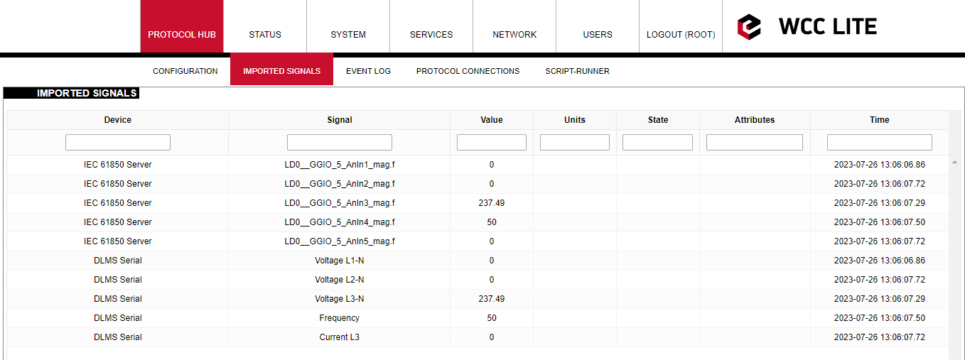](https://wiki.elseta.com/uploads/images/gallery/2023-07/image-1690365992182.png)
Fig. 13 Measurements represented in Wcc Lite WEB "Imported signals" tab.
#### Files used in this article:
1\. ICD file: [WCC.icd](https://wiki.elseta.com/attachments/602)
2\. Server Model file: [WCC.cfg](https://wiki.elseta.com/attachments/603)
3\. Excel configuration file: [WCC\_full.xlsx](https://wiki.elseta.com/attachments/604)
4\. Excel Utility software: [Excel Utility](https://wiki.elseta.com/attachments/55)
5\. Wcc Lite firmware: [Wcc 1.7.0 RTU](https://wiki.elseta.com/attachments/47)
# DLMS Serial to IEC61850-server protocol conversion (WCC Lite FW: 1.10.0 or newer)
#### Description
This article explains how to configure the WCC Lite to convert data from a DLMS Serial protocol meter to an IEC 61850 server. The process includes device setup, signal mapping, server model creation, configuration upload, and validation through IEDscout.
[](https://wiki.elseta.com/uploads/images/gallery/2023-07/image-1690356504117.png)
Fig 1. Connecting Meter with DLMS serial protocol to WCC Lite and IEC61850 server
#### Preparatiom
To begin, ensure that the WCC Lite is physically installed according to manufacturer's instructions. Connect your computer to the WCC Lite using an Ethernet cable via the ETH0 port. Log in using the default credentials and perform basic setup, including system name, network parameters, and user management. You can find additional assistance in related [How to](https://wiki.elseta.com/books/how-to) articles.
#### Excel configuration
Configuration is done using an Excel file containing two main sheets: Devices and Signals. In the Devices sheet, add a row for the DLMS meter. Specify its communication settings, including serial port parameters, protocol (DLMS), and authentication details. The serial number should also match the connected device.
Add required information for the connected Gama meter with **DLMS Serial** protocol:
**name**
**description**
**device\_alias**
**protocol**
**serial\_number**
**device**
**databits**
**stopbits**
**baudrate**
**parity**
DLMS Serial
DLMS Serial
DLMS\_Meter
DLMS
2250259
PORT1
8
1
4800
none
**flowcontrol**
**enable**
**auth**
**logical\_address**
**address\_size**
**client\_address**
**type**
**mode**
none
1
LOW
1
2
32
SN
DLMS-HDLC
More information about DLMS protocol configuration is provided in [DLMS/COSEM](https://wiki.elseta.com/books/manual-18/page/171-dlmscosem) article.
Next, define a second row for the IEC 61850 server. Assign an alias and bind it to the 0.0.0.0 address. **The model filename you enter here will later be matched to the server model file you generate.** Define the IED name, logical device, access point, and port settings.
Add **IEC 61850 server** protocol required information:
**name**
**description**
**device\_alias**
**protocol**
**bind\_address**
IEC 61850 Server
IEC 61850 Server
iec\_61850\_server
iec 61850 server
0.0.0.0
**ied\_name**
**access\_point**
**port**
**auth**
**host**
**model\_filename**
WCCLITE
LD0
102
NONE
192.168.1.2
WCC\_test
More information about IEC 61850 server protocol configuration is provided in [IEC 61850 server](https://wiki.elseta.com/books/manual-18/page/152-iec-61850-server) article.
#### Configure signals (Excel "Signals\_DLMS" sheet)
Move to the Signals sheets. You can split the signal definitions into separate sheets (e.g., `SignalsDLMS` and `SignalsIEC61850`) or place them all in a single one. For DLMS signals, enter OBIS codes that define what data to collect, such as voltages, frequency, and current. OBIS codes break down into six segments, each representing a specific aspect of the measured data—like media type, channel, physical quantity, and instantaneous value. In this example, voltage and frequency measurements are mapped using OBIS codes starting with 1, indicating electricity.
In the IEC 61850 signal sheet, link each IEC signal to its source signal from the DLMS device. This is done by referencing the alias of the source device and signal. You also need to define logical device instance, logical node class and instance, common data class, and data attributes. This mapping ensures that IEC 61850 server outputs correspond to the actual readings from the DLMS meter.
##### Add signal information for the connected meter with DLMS Serial protocol
(Excel **SignalsDLMS** sheet):
**signal\_name**
**device\_alias**
**signal\_alias**
**obis\_job**
Voltage L1-N
DLMS\_Meter
Voltage\_L1-N
1.0.32.7.0.255
Voltage L2-N
DLMS\_Meter
Voltage\_L2-N
1.0.52.7.0.255
Voltage L3-N
DLMS\_Meter
Voltage\_L3-N
1.0.72.7.0.255
Frequency
DLMS\_Meter
Frequency
1.0.14.7.0.255
Current L3
DLMS\_Meter
Current\_L3
1.0.71.7.0.255
**obis\_job** - Objects are identified with the help of OBIS (Object Identification System) codes.
1. The first number of OBIS code defines the media (energy type) to which the metering is related. Nonmedia
related information is handled as abstract data. For example all obis\_jobs in the table above starts with numbers 1 which stands for "Electricity related objects".
2. The second number defines the channel number, i.e. the number of the input of a metering
equipment having several inputs for the measurement of energy of the same or different types
(e.g. in data concentrators, registration units). Data from different sources can thus be
identified. The definitions for this value group are independent from the value of the first number. In all obis\_jobs from the table above second number is set to zero which means that no channel is specified.
3. The third number defines the abstract or physical data items related to the information
source concerned, for example current, voltage, power, volume, temperature. The definitions
depend on the value of the first number. For example in obis\_jobs from the table above number 72 means voltage L3 and number 14 means frequency.
4. The forth number defines types, or the result of the processing of physical quantities
identified with the numbers 1 and 3, according to various specific algorithms. The
algorithms can deliver energy and demand quantities as well as other physical quantities. In all obis\_jobs from the table above forth number is set to 7 which stands for "Instantaneous value".
5. The value of the fifth number defines further processing or classification of quantities identified by numbers 1 to 4. In case of the first obis\_job number 0 means that all harmonics of the signal along with its fundamental frequency are going to be taken into consideration.
6. The value of the sixth number defines the storage of data, identified by numbers 1 to 5, according to
different billing periods. Where this is not relevant, this value group can be used for further
classification. In all obis\_jobs from the table above last number is set to 255 which means that data is not used.
#### Add signals information for **IEC 61850 server** (Excel Signals\_IEC61850 sheet):
**signal\_name**
**device\_alias**
**signal\_alias**
**source\_device\_alias**
**source\_signal\_alias**
LD0\_\_GGIO\_5\_AnIn1\_mag.f
iec\_61850\_server
LD0\_\_GGIO\_5\_AnIn1\_mag.f
DLMS\_Meter
Voltage\_L1-N
LD0\_\_GGIO\_5\_AnIn2\_mag.f
iec\_61850\_server
LD0\_\_GGIO\_5\_AnIn2\_mag.f
DLMS\_Meter
Voltage\_L2-N
LD0\_\_GGIO\_5\_AnIn3\_mag.f
iec\_61850\_server
LD0\_\_GGIO\_5\_AnIn3\_mag.f
DLMS\_Meter
Voltage\_L3-N
LD0\_\_GGIO\_5\_AnIn4\_mag.f
iec\_61850\_server
LD0\_\_GGIO\_5\_AnIn4\_mag.f
DLMS\_Meter
Frequency
LD0\_\_GGIO\_5\_AnIn5\_mag.f
iec\_61850\_server
LD0\_\_GGIO\_5\_AnIn5\_mag.f
DLMS\_Meter
Current\_L3
**ld\_instance**
**ln\_class**
**ln\_instance**
**cdc**
**data\_object**
**da\_fc**
**number\_type**
**da\_value**
**Log**
LD0
GGIO
5
MV
AnIn1
MX
FLOAT32
mag.f
1
LD0
GGIO
5
MV
AnIn2
MX
FLOAT32
mag.f
1
LD0
GGIO
5
MV
AnIn3
MX
FLOAT32
mag.f
1
LD0
GGIO
5
MV
AnIn4
MX
FLOAT32
mag.f
1
LD0
GGIO
5
MV
AnIn5
MX
FLOAT32
mag.f
1
From the table above it can be seen that IEC 61850 server signals has **source\_device\_alias** and **source\_signal\_alias** in which device\_alias and signal\_alias of DLMS meter signals are described. That is how DLMS meter signals are linked to IEC61850 server signals, so the measurements of the DLMS meter could be transported to IEC 61850 server.
For more detailed DLMS protocol communication analysis Gurux DLMS Director application can be used.
#### Generating Server Model file for WCC Lite
For the IEC 61850 server to function, a model file is required. This file is based on an ICD file, which describes the server’s capability. The ICD file serves both for generating the server model and simulating client behavior with tools like IEDscout.
Open the WCC Excel Utility and choose the appropriate version from a drop-down menu in the Configuration tab (Fig. 3).
[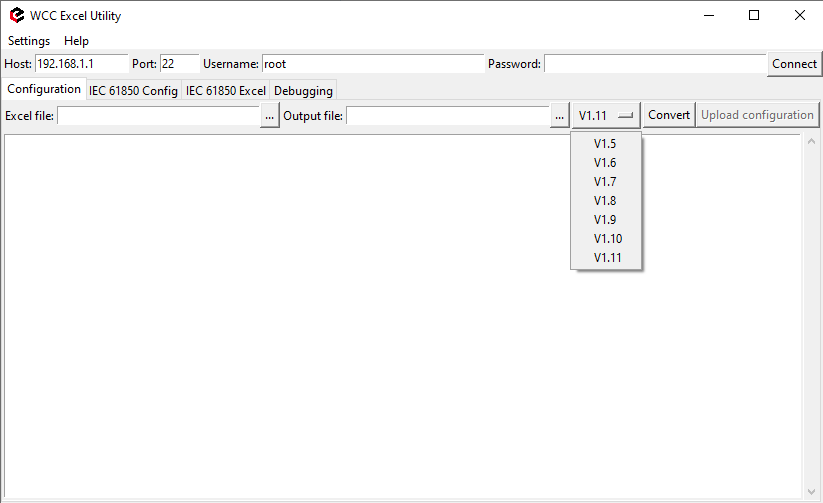](https://wiki.elseta.com/uploads/images/gallery/2025-05/image-1747651527442.png)Fig. 3 Choosing the right version
Navigate to the IEC61850 Config tab, select the ICD file, and define the output directory for the server model file (Fig. 4). Ensure the filename matches the one specified in the Devices sheet. Press Convert to generate the model file. Then upload this file to the WCC Lite via the web interface (Fig. 5).
[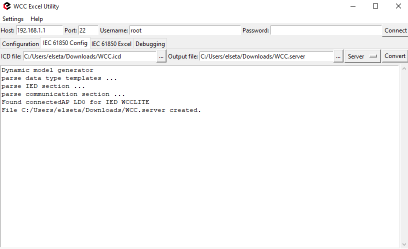](https://wiki.elseta.com/uploads/images/gallery/2025-05/image-1747651581578.png)Fig. 4 Generating Server Model file
Fig. 5 Uploading IEC 61850 Server Model file to Wcc Lite WEB
#### Uploading Wcc Lite configuration
With the server model uploaded, confirm that the host IP address defined for the IEC 61850 server in the Excel file matches your computer’s IP address. You can set this manually in the network adapter settings to ensure proper communication.. This is shown in Fig. 6.
[](https://wiki.elseta.com/uploads/images/gallery/2023-07/image-1690357201276.png)
Fig. 6 Changing PC IP (TCP/IPv4) to match the Host IP in configuration
Return to the WCC Lite web interface and upload the Excel configuration file. Select the file and click "Import configuration" (Fig. 7) The import process may take a few minutes to complete.
Fig. 7 Uploading Excel configuration to Wcc Lite.
#### Starting IEC 61850 server
To start the IEC 61850 server in debug mode, use a terminal emulator like PuTTY or a Linux subsystem terminal. This launches the service in debug mode, which outputs live data and connection logs. Following commands should be entered in the terminal window:
1\. Connecting to Wcc Lite:
```Powershell
ssh root@192.168.1.1
```
2\. Login: root Password: your Wcc Lite pasword
3\. Stopping the IEC 61850 service:
```shell
/etc/init.d/iec61850-server stop
```
4\. Starting IEC61850 server in debugger mode:
```shell
iec61850-server -d7 -c /etc/iec61850-server/iec61850-server.json
```
After these commands are executed, the IEC 61850 server is started, it is shown in Fig. 8.
[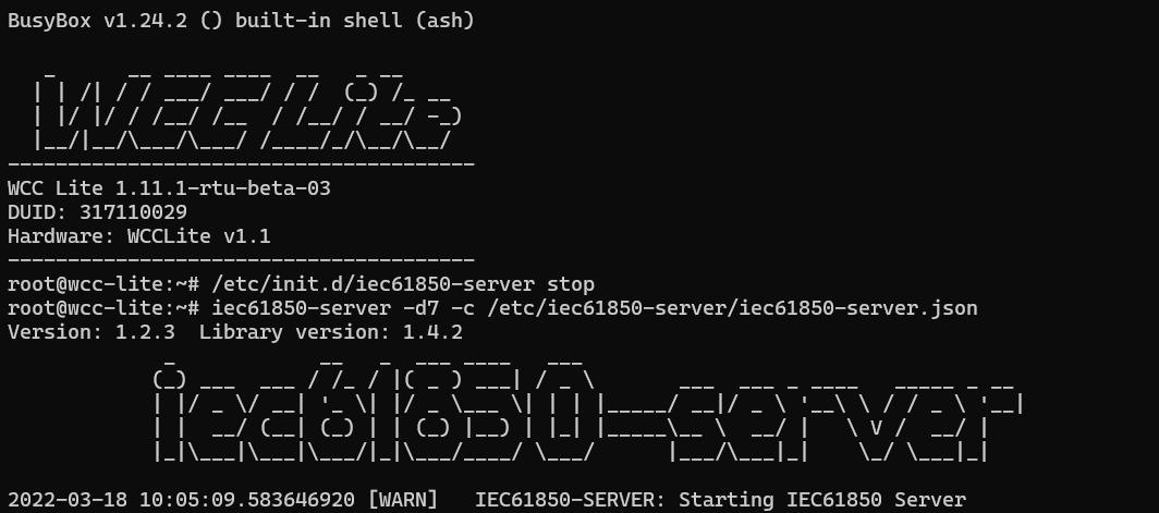](https://wiki.elseta.com/uploads/images/gallery/2025-05/image-1747658932821.png)Fig. 8 Connecting to Wcc Lite through SSH and starting IEC61850 server
## Connecting to Wcc Lite (server) on IEDscout (client)
To verify the system, open IEDscout or another IEC 61850 client simulator. Load the ICD file, discover the IED using the WCC Lite’s IP address, and if needed, press "Online" in IEDscout to establish the connection (Fig. 9). In the WCC Lite’s web interface, navigate to the protocol connections tab to confirm both DLMS and IEC 61850 are connected (Fig. 10) As measurements appear in the debugger terminal (Fig. 11), return to IEDscout and click "Read" to refresh the values (Fig. 12)
[](https://wiki.elseta.com/uploads/images/gallery/2023-07/image-1690360585596.png)Fig. 9 Starting IED on IEDscout
[](https://wiki.elseta.com/uploads/images/gallery/2023-07/image-1690361170192.png)
Fig. 10 Protocol connections
[](https://wiki.elseta.com/uploads/images/gallery/2023-07/image-1690361780503.png)
Fig. 11 Measurements from Meter linked to IEC61850 server signals
[](https://wiki.elseta.com/uploads/images/gallery/2023-07/image-1690361918281.png)
Fig. 12 Measurements appeared in IEDscout software
Finally, you can view all collected and converted data on the WCC Lite web interface under the *Imported Signals* tab. This confirms that your DLMS meter data is now available through the IEC 61850 server (Fig. 13)
[](https://wiki.elseta.com/uploads/images/gallery/2023-07/image-1690365992182.png)
Fig. 13 Measurements represented in WCC Lite WEB *Imported signals* tab.
#### Files used in this article:
1\. ICD file: [WCC.icd](https://wiki.elseta.com/attachments/675)
2\. Server Model file: [WCC.server](https://wiki.elseta.com/attachments/677)
3\. Excel configuration file: [WCC.xlsx](https://wiki.elseta.com/attachments/676)
4\. Excel Utility software and firmware : [Download](https://wiki.elseta.com/books/wcclite-downloads/page/firmware-and-tools)
# Firmware update
To upgrade the firmware (FW) of the WCC Lite, open the web interface and navigate to **System → Backup / Flash Firmware**.
Note that after upgrading, the WCC Lite will revert to default settings. To preserve existing configurations, enable the checkbox to **Keep settings** (which saves all settings) or **Keep only network settings** if needed. However, using the **Keep settings** option is only safe when the firmware version change is minor—i.e., only the third version number differs (for example, 1.6.2 → 1.6.3). Using this option across major version jumps may corrupt settings.
To begin the upgrade, click **Choose File**, select the previously downloaded [sysupgrade file](https://wiki.elseta.com/books/wcclite-downloads/page/firmware-and-tools), and then press **Flash Image**.
Starting from version **1.10.0**, signed firmware validation was introduced. Firmware files from this version onward will have the `.bin.tar.gz` extension. WCC Lite versions **older than 1.10.0** do not support uploading `.bin.tar.gz` files directly. In such cases, you must extract the downloaded file twice until it becomes a `.bin` file. This step is necessary only if upgrading from an earlier version like 1.9.3 to 1.10.0 or newer
A pop-up will appear prompting you to confirm the upgrade process within 120 seconds, or the upgrade will be canceled. Click **OK** to proceed.[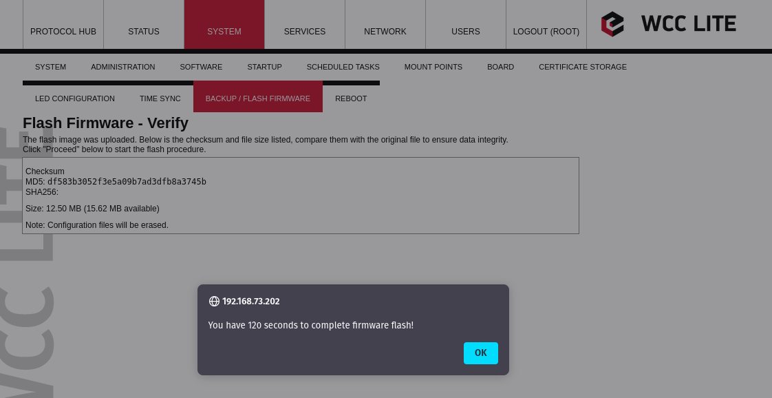](https://wiki.elseta.com/uploads/images/gallery/2022-06/image-1655190719778.png)The next window will display a firmware verification step. Ensure that the checksum shown matches the one provided on the downloads page. It is recommended to check at least the first 5 characters of the checksum. Click **Proceed** to continue.
[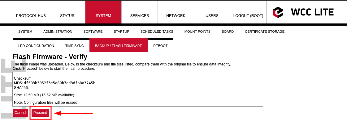](https://wiki.elseta.com/uploads/images/gallery/2022-06/image-1655190731680.png)You will then see a page indicating that the system is flashing the firmware. This page is for display purposes only, you may close it if needed.[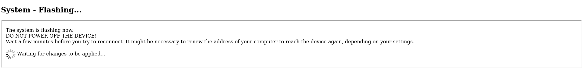](https://wiki.elseta.com/uploads/images/gallery/2022-06/image-1655192321413.png)
**Do not power off the device during this process**, as this will corrupt the firmware and render the device inoperable.
After approximately 10 minutes, you can attempt to reconnect to the WCC Lite.# Lua runner examples
# Configuration Example With Default and Saved Values (Modbus TCP, IEC104)
#### Excel configuration
An Excel configuration for WCC Lite is needed to control signals with a Lua script. In this case, three devices are required: one for Modbus TCP Master, one for IEC104-slave and one for Lua runner. Configuration example:
[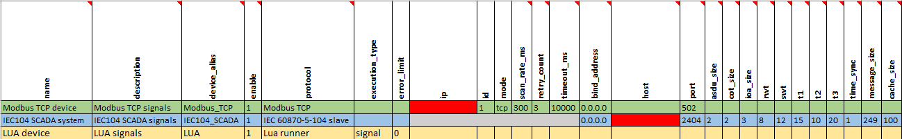](https://wiki.elseta.com/uploads/images/gallery/2023-08/image-1691501602369.png)
To connect slave and master devices, the master's IP address and the slave's host addresses have to be specified. Modbus IP address will be the address of Wi-Fi to which the computer is connected (this can be checked on the terminal window with the command *ipconfig*), and the host address for IEC104 slave protocol will be the IP address to which WCC Lite is connected. To reach the device via these addresses, WCC Lite has to be connected to the internet.
When creating an Excel configuration with Lua, there is an option **default value** for the signal. This value will be set to the signal right after uploading the configuration, or if the script does not return any saved values.
Signals sheet:
[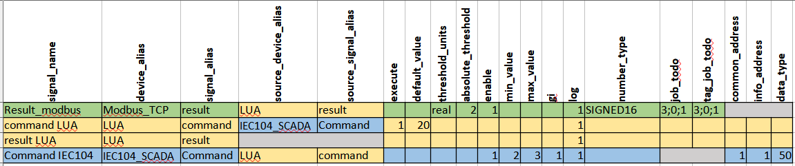](https://wiki.elseta.com/uploads/images/gallery/2023-08/image-1692706261790.png)
As it is seen from example values, such as **min\_value** and **max\_value,** can be added to determine the limits of a signal. This way command signal will only return results which are within this range. Otherwise command value will have negative cot with invalid, non topical or overflow attributes and new value will not be sent to result signals. As configured, until command value is sent default value will be represented for Lua command signal. For saved values to be represented a Lua script is needed.
#### Lua script
Lua script example for this configuration is shown below:
```Lua
local saved = get(signals.result) --getting result signal which is equated to new variable 'saved' local command = get(signals.command) --getting command signal which is equated to new variable 'command'
--get() function returns nill if there is no valid value
if not command then --if command is not nill if saved then --if signal is not nill publish(signals.result, saved.value) --this value is published to result signals and saved value end return 0 end
local time_diff = time_ms() - tonumber(command.time) --compares command time and real time local is_command = time_diff < 30000 and time_diff > -30000 --if command time differs from --real time more than 30s it will not be executed
if string.find(command.attributes, "nt") or string.find(command.attributes, "iv") or string.find(command.attributes, "ov") then --searching if signal has negative attributes if is_command then --if command execution time is not exceeding the limits then command.attributes = "cot=7,cotn" --equates negative cot values to response signal attributes publish(signals.command, command) -- and publishes value to command signals and value if saved then --if there is saved value then publish(signals.result, saved.value) --restores saved value to result signals end return 0 end else if is_command then command.attributes = "cot=7" publish(signals.command, command) --in this cycle command value is being returned as well as --cot7 and cot10 values in case given signal is command and has no negative attributes command.attributes = "cot=10" publish(signals.command, command) --publishes response to the command save(signals.result, command.value) --command value is being saved to result signal end publish(signals.result, command.value) --in this row command value is being published to result signals end
```
#### Uploading configuration and Lua script to WCC Lite
First Excel configuration needs to be uploaded to WCC Lite:
[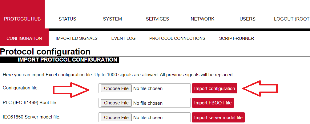](https://wiki.elseta.com/uploads/images/gallery/2022-12/image-1671526558865.png)
After uploading configuration default value will be shown:
[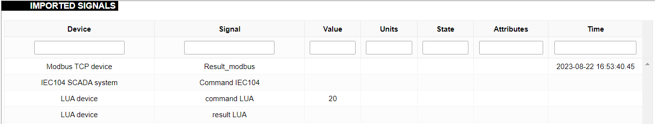](https://wiki.elseta.com/uploads/images/gallery/2023-08/image-1692712552551.png)
After uploading configuration no errors should appear and all signal should be represented on the web. To upload Lua script go to *Script-Runner*, select *upload script* and then *start:*
[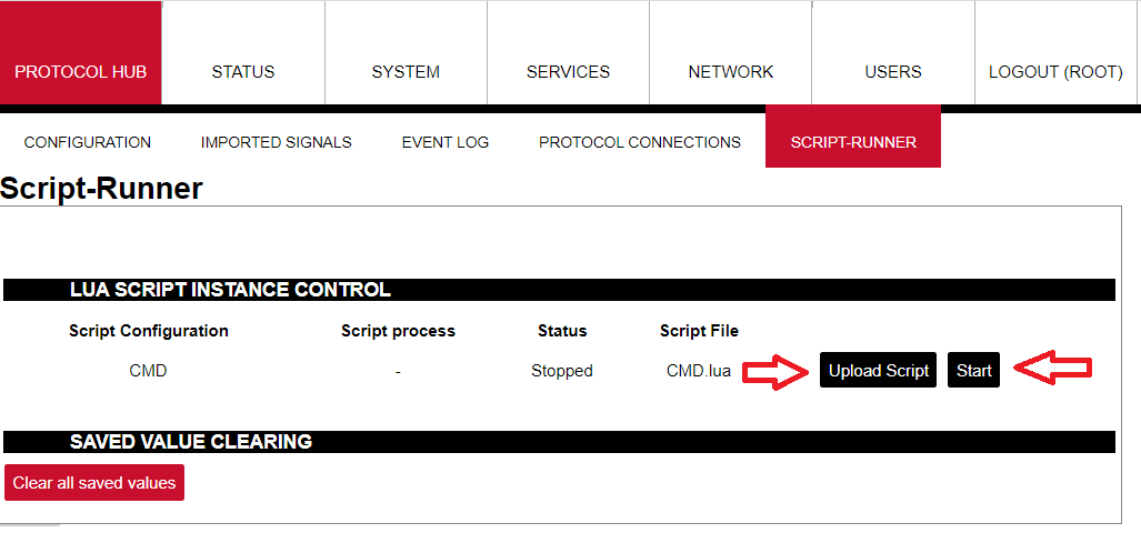](https://wiki.elseta.com/uploads/images/gallery/2022-12/image-1671526957681.png)
#### Connecting master and slave via Vinci software
##### Connecting IEC104 slave
In order to connect to WCC Lite via IEC104 protocol, select Master(Client) mode on Vinci:
[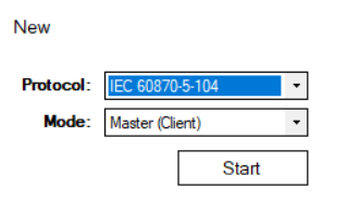](https://wiki.elseta.com/uploads/images/gallery/2022-12/image-1671528870849.png)
Check Settings tab to match excel configuration:
[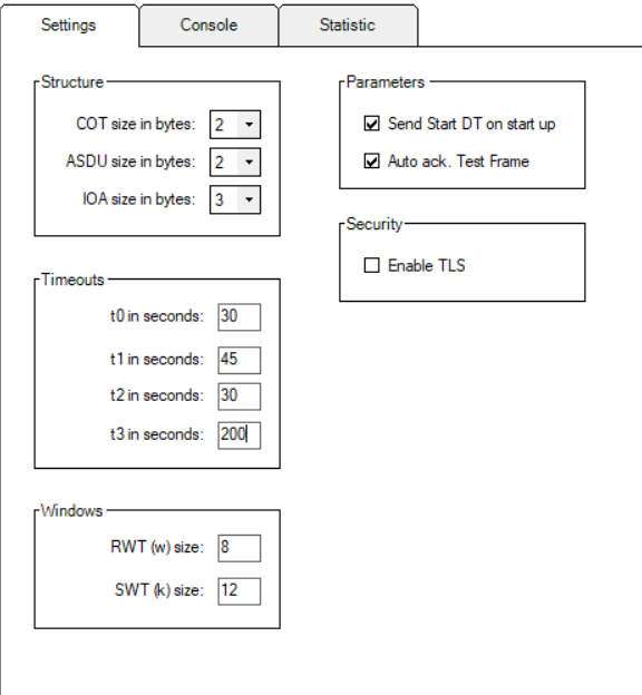](https://wiki.elseta.com/uploads/images/gallery/2022-12/image-1671528969827.png)
Specify IP address which should match the one in Excel configuration.
##### Connecting ModbusTCP master:
To connect ModbusTCP Master, select Slave (Server) mode on Vinci:
[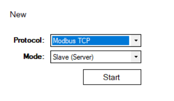](https://wiki.elseta.com/uploads/images/gallery/2022-12/image-1671530055509.png)
Check address to match **id** in Excel configuration:
[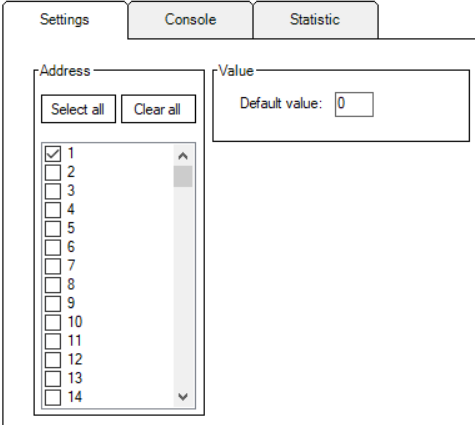](https://wiki.elseta.com/uploads/images/gallery/2023-08/image-1691399259812.png)
Match the IP address given in Excel configuration as well.
#### Executing commands
Start both master and slave simulations on Vinci. Check if both protocols are connected to WCC Lite on the web tab *Protocol Connections:*
[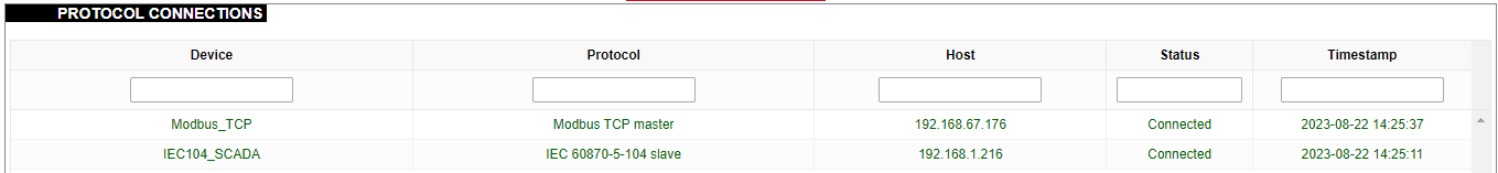](https://wiki.elseta.com/uploads/images/gallery/2023-08/image-1692703562023.png)
To execute commands, open Vinci program with IEC104 master running. Here, go to *System* tab and fill in required fields such as IOA and select data type indicated in Excel configuration. First, try sending value that is outside the set range:
[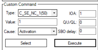](https://wiki.elseta.com/uploads/images/gallery/2023-08/image-1692952309993.png)
After selecting *execute* this value will not be showed on the web and positive cot6 and negative cot7 values will be seen on Vinci IEC104 simulation window. Positive cot6 indicates command activation and negative cot7 means that command activation confirmation was denied. The command signal value will not be represented as result signals, because it is determined in the script, that signals with negative attributes will not be published.
[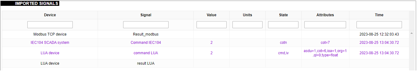](https://wiki.elseta.com/uploads/images/gallery/2023-08/image-1692957902714.png)
Now specify value which will be sent as a result and is within the given range.
[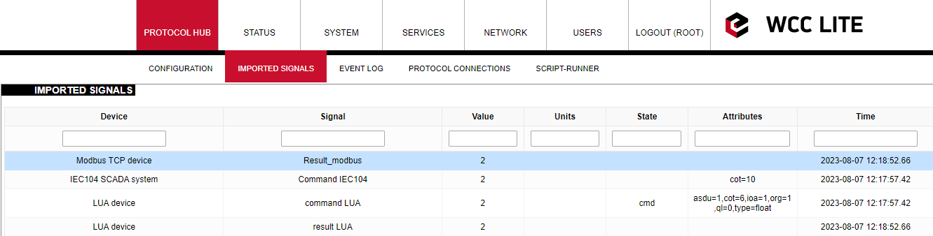](https://wiki.elseta.com/uploads/images/gallery/2023-08/image-1691399941593.png)
Positive cot7 and cot10 values will be seen on the Vinci IEC104 simulation window:
[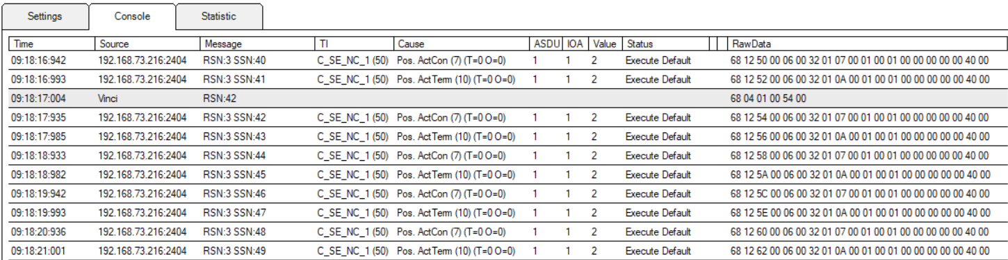](https://wiki.elseta.com/uploads/images/gallery/2023-08/image-1691400062905.png)
This value will also be represented on Modbus TCP master Vinci simulation window:
[](https://wiki.elseta.com/uploads/images/gallery/2023-08/image-1691400136020.png)
To show what happens if the value is not within determined range after the correct value has been sent before, try executing command with smaller or larger value specified:
[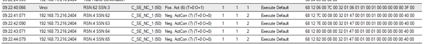](https://wiki.elseta.com/uploads/images/gallery/2023-08/image-1691400179325.png)
Again, positive cot6 and negative cot7 values is seen on Vinci window.
[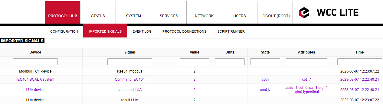](https://wiki.elseta.com/uploads/images/gallery/2023-08/image-1691400197027.png)
As seen on WCC Lite web window, command signals have negative attributes and result signals have the same value as before, because it was saved by Lua script. This example shows that Lua runner can be used to save certain values to signal. For example after the restart saved value could be seen on command signal to determine minimum or maximum value, last value or typical value. This solution could be useful for protecting important data even after reboot or connection faults.
Configuration --> [Download](https://wiki.elseta.com/attachments/552)
Lua script --> [Download](https://wiki.elseta.com/attachments/542)
# Signal Delay with Lua
For delaying the response of command execution, the Lua runner could be used as one of the solutions. In this example, IEC104 and Modbus TCP are used. IEC104 protocol sends the command to Modbus and Lua signals, and the results are represented as two separate signals. To create an Excel configuration for WCC Lite, in this case device sheet should look like this:
[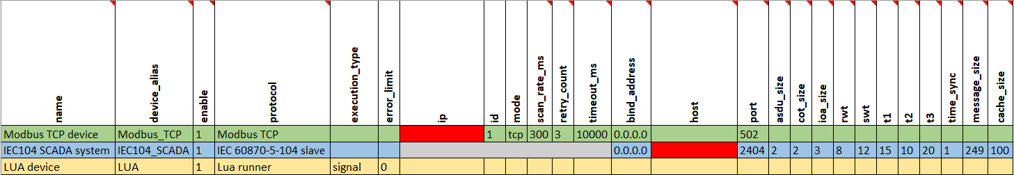](https://wiki.elseta.com/uploads/images/gallery/2023-08/image-1691574338163.png)
In the fields marked red, for Modbus TCP, enter the IP address of the Wi-Fi connected to a computer, and for IEC104, enter the IP address of WCC Lite. Map the signals as shown below:
[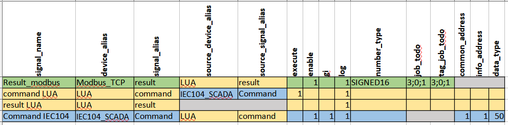](https://wiki.elseta.com/uploads/images/gallery/2023-08/image-1692965126845.png)
IEC104 SCADA will send a command, which will then go to the Lua signal. Lua signal will send the response back to the IEC104 SCADA and Modbus TCP result signal.
For delaying signal response, a Lua script could be written in many ways, however, the simplest and effective one is to determine a wait time before publishing signal values to result signals. So in this case Lua script will look like this:
```Lua
local saved = get(signals.result)--getting result signal which is equated to new variable 'saved' local command = get(signals.command) --getting command signal which is equated to new variable 'command'
if not command then if saved then publish(signals.result, saved.value)--this value is published to result signals and saved value end return 0 end
if string.find(command.attributes, "nt") or string.find(command.attributes, "iv") or string.find(command.attributes, "ov") then --searching if signal has negative attributes if command then command.attributes = "cot=7,cotn"--equates negative cot values to response signal attributes publish(signals.command, command)-- and publishes value to command signals and value if saved then publish(signals.result, saved.value)--restores saved value to result signals end return 0 end else if command then command.attributes = "cot=7" publish(signals.command, command)--in this cycle command value is being returned as well as --cot7 and cot10 values in case given signal is command type and has no negative attributes command.attributes = "cot=10" publish(signals.command, command) --publishes response to the command save(signals.result, command.value)--command value is being saved to result signal end local sleepTime = 30 sleep(sleepTime) --before publishing values to result signals script waits 30s publish(signals.result, command.value)--in this row values are being published to result signals end
```
After entering values to empty Excel configuration fields, upload the configuration to WCC Lite (it should upload without any errors):
[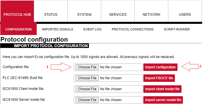](https://wiki.elseta.com/uploads/images/gallery/2023-08/image-1691483399099.png)
Upload the Lua script to the script runner and press start. After this, **Status** should show *Running,* and the script process number will appear.[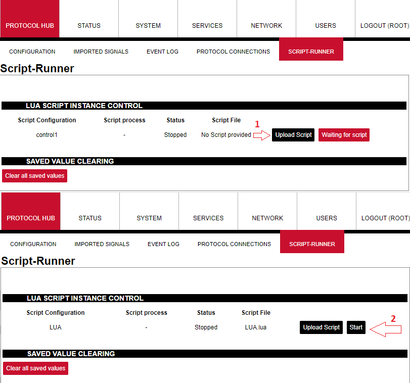](https://wiki.elseta.com/uploads/images/gallery/2023-08/image-1691650520213.png)
Open Vinci as an IEC104 master, enter the IP address of WCC Lite and start communication. Then open another Vinci window and connect Modbus TCP master – select Modbus TCP slave in Vinci and enter the same IP address as set in the Excel configuration for the Modbus device. With both communications running, check **Protocol connections** on the WCC Lite web interface, it should show *connected.* From the IEC104 Vinci window, go to the *System* tab. Select command determined in the Excel configuration (50), IOA (1) and value (eg, 2).
[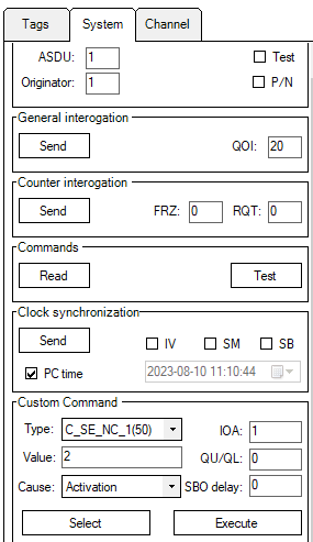](https://wiki.elseta.com/uploads/images/gallery/2023-08/image-1691656106450.png)
Execute the command and check *Imported signals:*
[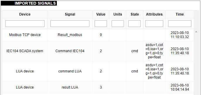](https://wiki.elseta.com/uploads/images/gallery/2023-08/image-1691656557970.png)
After 30s the result signals will now have the same value:
[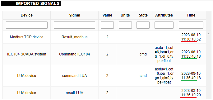](https://wiki.elseta.com/uploads/images/gallery/2023-08/image-1691657076669.png)
Signal delay could be used as a tool to synchronise signals so all the values are received at the same time. It can also be used to schedule commands or tasks when a delay is required. Since Lua is one of the fastest programming languages, it is the most effective instrument to be used in such matters.
Configuration --> [Download](https://wiki.elseta.com/attachments/553)
Lua script --> [Download](https://wiki.elseta.com/attachments/554)
# Mathematical Operations With Lua (FW version 1.7)
Mathematical operations can be applied to Lua signals as in any other protocol. This can be done by configuring WCC Lite according to the solution needed. To create an example which tests multiple mathematical operations, an Excel configuration and a Lua script are required. The device sheet should look similar to this:
[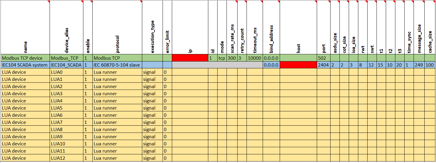](https://wiki.elseta.com/uploads/images/gallery/2023-08/image-1691759419298.png)
Each Lua device is created to send result values to Modbus TCP signals with different mathematical functions applied. This way, the same Lua script can be reused and is more optimal since the signal alias for each device can stay the same. There are many other solutions, but this one allows us to observe results more clearly.
In the field "ip" for Modbus TCP master, enter the IP address of the Wi-Fi connection for the computer in use. In the field "host" for IEC104 slave protocol, enter the IP address of the WCC Lite device.
Signals for these devices should be mapped, for example, to this:
[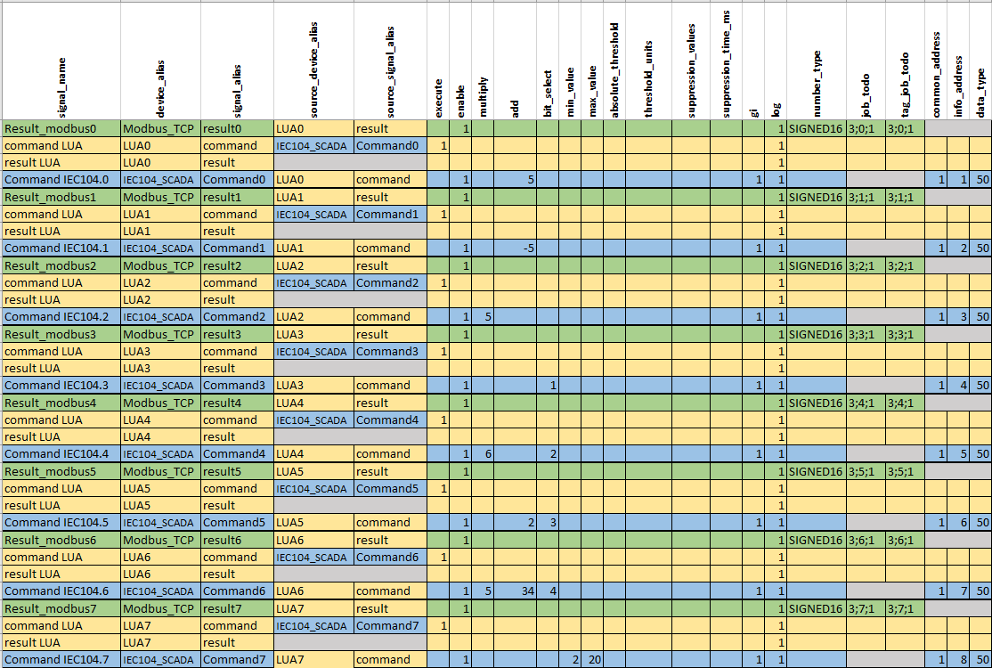](https://wiki.elseta.com/uploads/images/gallery/2023-08/image-1691761247612.png)
Each Lua device has command and result signals. Command received from the IEC104 protocol is sent to the Lua command signal, and then this signal sends back a response for the IEC104 protocol. If the response does not have negative cot attributes, the value is then sent to the Lua result signal, which sends the value to the Modbus TCP result signal. Mathematical operations are applied to IEC104 protocol signals since it is the one sending the commands.
As mentioned before Lua script for each Lua device is going to be unchanged and should look like this:
```Lua
local saved = get(signals.result) --getting result signal which is equated to new variable 'saved' local command = get(signals.command) --getting command signal which is equated to new variable 'command'
--get() function returns nill if there is no valid value
if not command then --if command is not nill if saved then --if signal is not nill publish(signals.result, saved.value) --this value is published to result signals and saved value end return 0 end
local time_diff = time_ms() - tonumber(command.time) --compares command time and real time local is_command = time_diff < 30000 and time_diff > -30000 --if command time differs from --real time more than 30s it will not be executed
if string.find(command.attributes, "nt") or string.find(command.attributes, "iv") or string.find(command.attributes, "ov") then --searching if signal has negative attributes if is_command then --if command execution time is not exceeding the limits then command.attributes = "cot=7,cotn" --equates negative cot values to response signal attributes publish(signals.command, command) -- and publishes value to command signals and value if saved then --if there is saved value then publish(signals.result, saved.value) --restores saved value to result signals end return 0 end else if is_command then command.attributes = "cot=7" publish(signals.command, command) --in this cycle command value is being returned as well as --cot7 and cot10 values in case given signal is command and has no negative attributes command.attributes = "cot=10" publish(signals.command, command) --publishes response to the command save(signals.result, command.value) --command value is being saved to result signal end publish(signals.result, command.value) --in this row command value is being published to result signals end
```
Upload Excel configuration to WCC Lite:
[](https://wiki.elseta.com/uploads/images/gallery/2022-12/image-1671526558865.png)
After uploading the configuration, no errors should appear, and all signals should be represented on the web. To upload a Lua script, go to *Script-Runner*, select *upload script* and then *start* (for each Lua device):
[](https://wiki.elseta.com/uploads/images/gallery/2023-08/image-1691650520213.png)
Open Vinci as an IEC104 master, enter the IP address of WCC Lite and start communication. Then open another Vinci window and connect Modbus TCP master – select Modbus TCP slave in Vinci and enter the same IP address as set in the Excel configuration for the Modbus device. With both communications running, check **Protocol connections** on the WCC Lite web interface, it should show *Connected*. From the IEC104 Vinci window, go to the System tab. Select command determined in the Excel configuration (50), IOA (different for each signal) and value. After executing the command, each signal (IEC104 command, Lua command, Lua result and Modbus result) will have the same value, which will now be with math applied. For example, a command with IOA=1 and value 1 is being executed. In Excel configuration for this signal, **add** a column has a value of 5, which means that this value is going to be added to the value sent and the result will be 6.
There can be multiple mathematical operations for one signal. For example, add, multiply, bit select, etc. If that is the case, math will be applied in typical order (eg, first bit select, then multiply, then add). A more detailed explanation about mathematical operations in Excel configuration can be found here: [Optional parameters for signals](https://wiki.elseta.com/books/manual163/page/182-optional-parameters-for-signals).
A user can also apply a mathematical condition for the signal value. For example, minimum or maximum value, threshold, suppression time for specific value, etc. Minimum and maximum values can be applied to set the range of the signal; if the value is smaller or larger signal state will show invalid or overflow. Thresholds can be used in many ways. It can be a specific value or a percentage. If the signal value passes the set threshold, it will be represented in the imported signals window. Threshold works by comparing the old value with the new value and then applying the condition of either representing the value or suppressing it, depending on the value change. Suppression value and suppression time are best used together because suppression time determines how long the specific value should be suppressed. There could be multiple values set for suppression. In Excel configuration, those values should be separated by a comma.
Mathematical operations combined with a Lua script are useful for many cases. They can be used for filtering data, converting units, applying specific mathematical logic or other solutions.
Configuration --> [Download](https://wiki.elseta.com/attachments/631)
Lua script --> [Download](https://wiki.elseta.com/attachments/548)
# Cronjob example
Lua device can be configured using a cron time expression. This way, script execution can be scheduled or executed at certain times. To create such a solution, the device sheet of the Excel configuration should look like this:[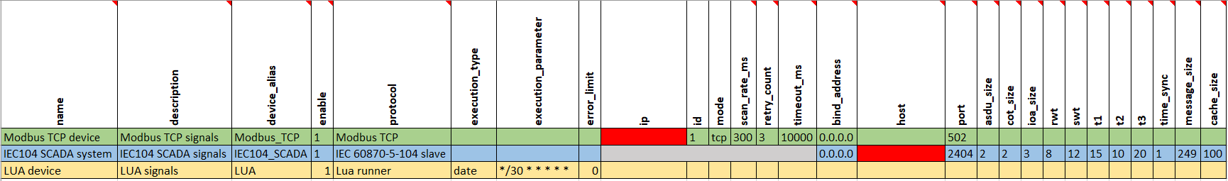](https://wiki.elseta.com/uploads/images/gallery/2023-08/image-1692192128948.png)
As seen in this configuration, the execution type for the Lua device is date, and the execution parameter is in a cron time expression. In this case script will be executed every 30 seconds starting from a mm:30 or a mm:00 mark. There are a lot of online cron expression parsers or generators to convert this expression to a more understandable form: [https://crontab.cronhub.io/.](https://crontab.cronhub.io/)
A Cron expression must have six variables; for instance, the code "0 \* \* \* \*" will not suffice because it contains only five variables. To rectify this, add a "0" to the beginning of the code: "0 0 \* \* \* \*". Similarly, the code "0 20-23,0-4,11 \* \* \*" which is displayed as correct on the website, to achieve the effect of every hour from 08:00 PM to 11:59 PM, 12:00 AM to 04:59 AM, and 11:00 AM, it must be adjusted as follows: "0 0 20-23,0-4,11 \* \* \*".
To complete the Excel configuration, fill out the red fields with the correct parameters. For the "ip" field, enter the IP address of the Wi-Fi connection that is connected to the computer. This can be checked by entering the command "ipconfig" in a terminal window. For the "host" field, enter the IP address of the WCC Lite device.
The signals sheet should look similar to this:
[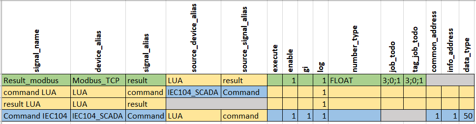](https://wiki.elseta.com/uploads/images/gallery/2023-08/image-1692193770966.png)
IEC104 SCADA will send a command, which will then go to the Lua signal. Lua signal will send the response back to the IEC104 SCADA and Modbus TCP result signal.
The Lua script in this case will be very simple. To show how Lua with cronjob can be used in real life, a calculation for kilowatts per hour has been added:
```Lua
local kW = tonumber(get_value(signals.command))--function "get_value" will get value from iec104 command --without any attributes this value is still in string form so funtion "tonumber" will convert it to number --a new variable is creted which is now equal to command value value = value or 0 --new variable is created. It has to be equal to itself or to 0 if the script is running --for the forst time value = (kW * 30/3600) + value --formula for calculating kilowatts. command value from iec104 is multiplied by time. --Since the script is being executed every 30s, this time needs to be converted to hours. an old value is being --added to new value, this way result value that is being published will grow every 30s publish(signals.result, value)--publishes result to result signals for lua and modbus TCP. --Since the script is being executed every 30s, those values will be refreshed every 30s as well
```
To test the functionality of this script, upload the Excel configuration to WCC Lite (it should upload without any errors):
[](https://wiki.elseta.com/uploads/images/gallery/2023-08/image-1691483399099.png)
Upload the Lua script to the script runner and press start. After this, **Status** should show *Running,* and the script process number will appear:
[](https://wiki.elseta.com/uploads/images/gallery/2023-08/image-1692256160683.png)
Open Vinci as an IEC104 master, enter the IP address of WCC Lite and start communication. Then open another Vinci window and connect Modbus TCP master – select Modbus TCP slave in Vinci and enter the same IP address as set in the Excel configuration for the Modbus device. With both communications running, check **Protocol connections** on the WCC Lite web interface, it should show *connected.* From the IEC104 Vinci window, go to the *System* tab. Select command determined in the Excel configuration (50), IOA (1) and value (for example 3600).
[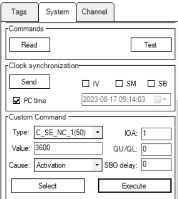](https://wiki.elseta.com/uploads/images/gallery/2023-08/image-1692256267495.png)
Execute the command and check *Imported signals:*
[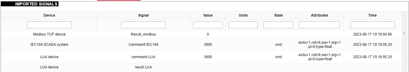](https://wiki.elseta.com/uploads/images/gallery/2023-08/image-1692256755579.png)
On a 30s mark, result signals will have a calculated value:
[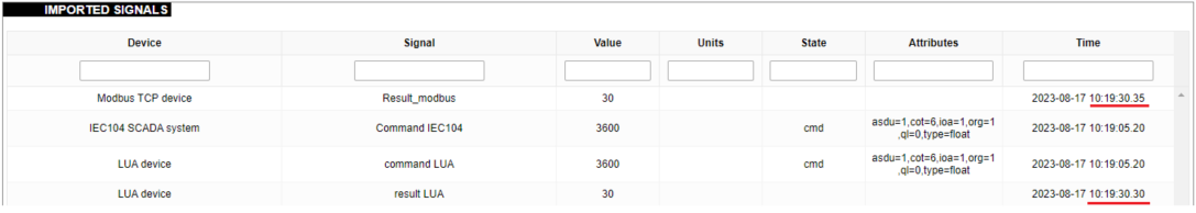](https://wiki.elseta.com/uploads/images/gallery/2023-08/image-1692256964491.png)
After another 30 seconds, a new value will be added to the old value, and the result signals will be updated accordingly:
[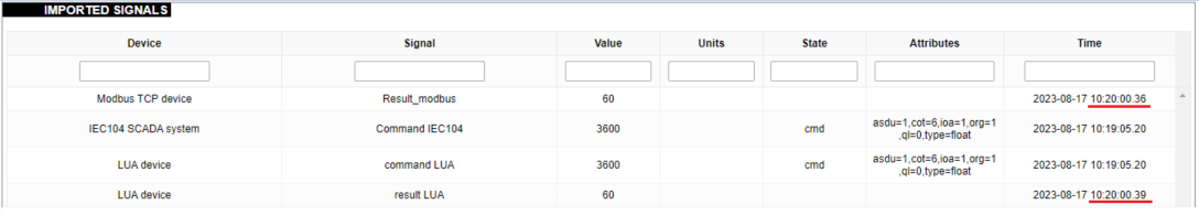](https://wiki.elseta.com/uploads/images/gallery/2023-08/image-1692257097082.png)
Cronjob with Lua can be used mainly to schedule tasks. It can also be used as a way to filter, monitor or control the data. As seen in this example, a Lua script can help calculate certain parameters, which then can be sorted using a cron time expression.
Configuration --> [Download](https://wiki.elseta.com/attachments/550)
Lua script --> [Download](https://wiki.elseta.com/attachments/549)
# Execution_signal example
The `execution_signal` parameter returns information about the specific signal that triggered execution. If there are multiple possible source signals, it identifies the one that initiated the execution. In this example, the Modbus RTU protocol is used. Configuration of devices:
[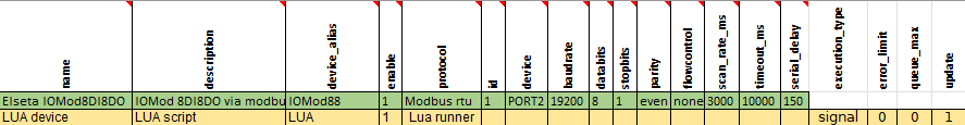](https://wiki.elseta.com/uploads/images/gallery/2025-02/image-1740645086014.png)
`Execution_signal` should always be "signal" when execution\_signal is used. PORT2 is used to connect IOMod 8DI8DO to WCC Lite via RS-485. IOMod signals configuration in this case:
[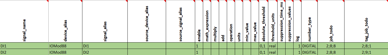](https://wiki.elseta.com/uploads/images/gallery/2025-02/image-1740645367520.png)
In this case, IOMod's input signals are used, but other signals can be used depending on needs. Map the signals as shown below:
[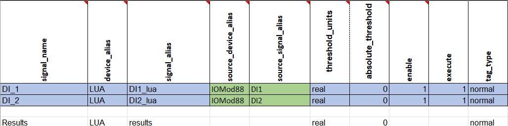](https://wiki.elseta.com/uploads/images/gallery/2025-02/image-1740646177825.png)
The first Lua signal is executing the first input signal, while the second Lua signal is executing the second input signal. The results signal is used to store information about the executed signal.
A Lua script can be written in various ways using the `execution_signal` parameter. However, in this example, a simple Lua script is used to retrieve the `signal_alias` of the executing signal by accessing `execution_signal.tag.signal_alias`:
```
local DI = execution_signal.tag.signal_alias
if DI == "DI1_lua" then
publish(signals.results, 1)
elseif DI == "DI2_lua" then
publish(signals.results, 2)
end
```
This is just one example of `execution_signal` usage. It can retrieve different information about executing a signal using:
- `execution_signal.tag.device_alias` - retrieves device\_alias
- `execution_signal.tag.signal_alias` - retrieves signal\_alias
- `execution_signal.value.value` - retrieves the value of the executing signal (for example, 1 or 0)
- `execution_signal.value.time` - retrieves system time in milliseconds (UNIX timestamp)
- `execution_signal.value.attributes` - retrieves attributes (for example, iv, nt, sb)
Upload the configuration to WCC Lite (it should upload without any errors):
[](https://wiki.elseta.com/uploads/images/gallery/2025-02/image-1740649584122.png)
Upload the Lua script to the script runner and press start. After this, **Status** should show *Running,* and the script process number will appear.
[](https://wiki.elseta.com/uploads/images/gallery/2025-02/image-1740649663116.png)
After activating the first input, in the WCC Lite web's imported signals tab, results should display 1:
[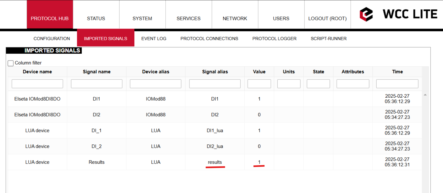](https://wiki.elseta.com/uploads/images/gallery/2025-02/image-1740650410927.png)
After activating the second input, in the WCC Lite web's imported signals tab, results should display 2:
[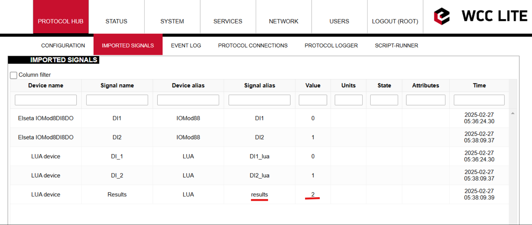](https://wiki.elseta.com/uploads/images/gallery/2025-02/image-1740650545463.png)
Configuration --> [Download](https://wiki.elseta.com/attachments/644)
Lua script --> [Download](https://wiki.elseta.com/attachments/645)
# Selecting specific bit as data (using bit_select)
### Description
Some devices send single-point data (0 and 1) in one register. To access the individual bits of the register you need to use the optional parameter - **bit\_select** parameter in the excel configuration. You can read about other optional parameters in the [manual section 18](https://wiki.elseta.com/link/859#bkmrk-optional-attributes). In short, you need to add one more column in the signals sheet with the name **bit\_select**, and in the signals, you use to specify which **bit** is assigned to the specific signal, starting from 0 to 15 if the register is 16 bits, if we need 2 registers, then from 0 to 32 and so on. In this example, we will explain how to read states from the Fanox fault protection relay.
### Configuration
The Fanox relay is communicating via Modbus, the address of the register is 500 using function 3 and the size of the register is 32 bits. So in the **job\_todo** field, we enter *3;500;2* because we need to read 2 registers. The number type is SIGNED32.
Below is the data that is written in the register as bits.
[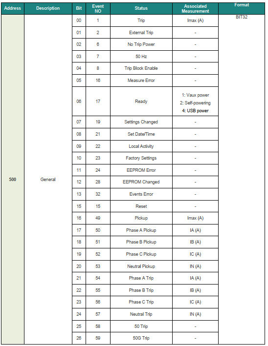](https://wiki.elseta.com/uploads/images/gallery/2023-02/image-1676894368945.png)
To read this data as signals we need to assign each of the bits from 0 to 26 to the created signals. All of the signals have the same **job\_todo, tag\_job\_todo** , and **number\_type**. But each signal has a specific bit. Below you can see the configuration of these signals.
[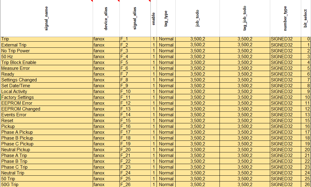](https://wiki.elseta.com/uploads/images/gallery/2023-02/image-1676894559730.png)
This example only displays how to read bit states via modbus, if you are using any other protocol you will need other parameters to read the data, but **bit\_select** parameter will stay.# IEC 61850 interoperability with IEC 104
### IEC 61850 Server
WCC Lite can act as a IEC 61850 server to serve data to remote SCADA systems. For example, WCC Lite can be used to acquire data from various protocols (Modbus, IEC 60870-5-103, etc.), this data can be redirected and propagated further to a single or multiple IEC 61850 clients. IEC 61850 Server supports TCP and TLS connection types. TCP connection can be secured with password authentication.
#### Commands
WCC Lite **IEC 61850 Server** implementation defines four command types which are described by their control model:
- **Case 1**: Direct control with normal security (direct-operate);
- **Case 2**: SBO control with normal security (operate-once or operate-many);
- **Case 3**: Direct control with enhanced security (direct-operate);
- **Case 4**: SBO control with enhanced security (operate-once or operate-many).
Normal security commands are considered for execution if the command signal is found in Excel configuration. There aren’t any additional checks in command execution in any master protocol.
Enhanced security commands need feedback from master protocol to either to succeed or fail. If feedback is not received within **command\_ack\_timeout\_ms** timeframe, the command is considered as failed.
Command value attributes (e.g. stVal) must be updated separately (if they need to be updated).
When using SBO commands, select is not routed to master protocol and select logic is performed only in IEC 61850 Server protocol.
### IEC 61850 Client
WCC Lite supports IEC 61850 Client command functionality that is used to control server devices such as protection relays. As relays require fast, secure and responsive interfaces, WCC Lite can be considered as a valid option.
#### Supported commands
Currently WCC Lite supports three types of commands:
- setVal command;
- setMag.f command;
- Oper.ctlVal commad.
If configured all commands will be added to excel using WCC-Utility.
### How commands function
**ctlModel**
**Description**
`status-only` (0)
Signal cannot be controlled
`direct-with-normal-security` (1)
Direct execution of a command
`sbo-with-normal-security` (2)
Command is selected and then executed
`direct-with-enhanced-security` (3)
Direct execution with a force wait of command termination
`sbo-with-enhanced-security` (4)
Command is selected and then executed; waiting for command termination
If ctlModel is `status-only`, messages via Redis will be ignored for this point, otherwise a Redis subscribe callback will be launched to handle commands as soon as they are sent over Redis. If CDC of a signal does not have means of control, `ctlModel` parameter is ignored.
#### Controlling remote equipment via commands
The control model provides a specific way to change the state of internal and external processes by a client. The control model can only be applied to data object instances of a controllable Common Data Class (CDC) and whose ctlModel DataAttribute is not set to `status-only`. Such data objects can be referred to as control objects. If controls are enabled in a IEC 61850 Server device the user can configure controls by filling control\_model column in Excel configuration with a control model **direct-with-normal-security, sbo-with-normal-security, direct-with-enhanced-security** and **sbo-with-enhanced-security** as well as setting functional constraint in `da_fc` column to CO.
#### Command “direct-with-normal-security”
As the IEC 61850 protocol states `direct-with-normal-security` command simply executes a command directly without any additional selection or execution logic. This is the most basic use of commands. Does not contain any **command termination** logic.
Provided below is command `direct-with-normal-security` standard logic of successful command and failed command:
[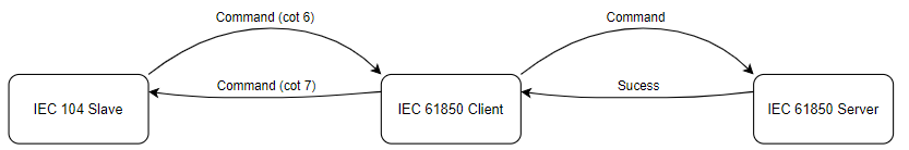](https://wiki.elseta.com/uploads/images/gallery/2023-04/image-1681813442978.png)
Failed command logic
#### Command “sbo-with-normal-security”
As the IEC 61850 protocol states `sbo-with-normal-security` command uses `select` and `execute` command logic. First, the command is selected, and then the execute command is sent to the server. Does not contain any **command termination** logic.
Provided below is command `sbo-with-normal-security` standard success and failure logic:
[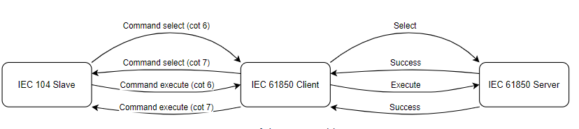](https://wiki.elseta.com/uploads/images/gallery/2023-04/image-1681813485538.png)
Failed command logic
Regarding failure, if server fails to select cotn 7 is returned the same way if an execute fails.
#### Command “direct-with-enhanced-security”
As the IEC 61850 protocol states `direct-with-enhanced-security` command uses `execute` command logic. Contain **command termination**. This means that command awaits for termination message. The execute command is sent to the server, and the command waits for a termination message from the server. If the termination message is received, the command is considered successful, and if not, the command is considered failed.
Provided below is command `direct-with-enhanced-security` standard success and failure logic:
[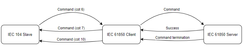](https://wiki.elseta.com/uploads/images/gallery/2023-04/image-1681813522448.png)
Failed command logic
In case of failure, no command termination is additionally provided.
#### Command “sbo-with-enhanced-security”
As the IEC 61850 protocol states `sbo-with-normal-security` command uses `select` and `execute` command logic. Contains **command termination**. This command is similar to the sbo-with-normal-security command, but it also responds with a termination message. If the command is successful, the termination message is sent to the client, and if not, the cotn 7 is returned.
Provided below is command `sbo-with-enhanced-security` standard success and failure logic:
[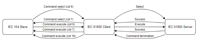](https://wiki.elseta.com/uploads/images/gallery/2023-04/image-1681813585887.png)
Failed command logic
In the case of failure, `sbo` command acts the same way as `direct` command. It does not send command termination, only cotn 7.
### Basic protocol functionality
The server (controlled station) delivers various data to the client.
• Data object values reported upon changes
• Data object values reported cyclically
• Responses to control commands
• Responses to read requests
To enable interoperability between IEC 61850 and IEC 60870-5-104, mapping between the two protocols is necessary. This mapping involves defining which data objects from one protocol correspond to which data objects in the other protocol.
[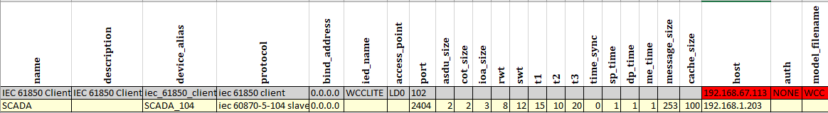](https://wiki.elseta.com/uploads/images/gallery/2023-04/image-1682431947176.png)
Excel configuration Devices sheet
[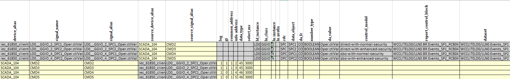](https://wiki.elseta.com/uploads/images/gallery/2023-04/image-1682491955449.png)
Excel configuration Signals sheet
The client can at any time request the present process data values by issuing interrogation commands. The command may be a general interrogation (GI) request, where all data objects with GI indication configured “1” are reported.
[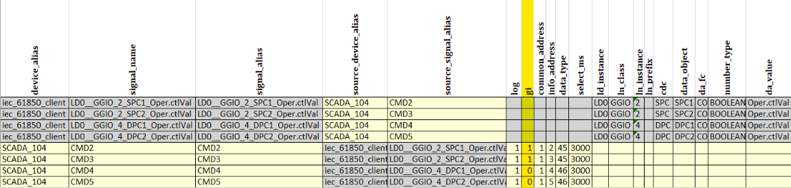](https://wiki.elseta.com/uploads/images/gallery/2023-04/image-1682491752307.png)
Signals sheet
### IEC 60870-5-104 data objects
**Single-point information**
Single-point information is derived from several IEC 61850 boolean data attributes
• SPS.stVal
• SPC.stVal
Type
ASDU
GI
1
M\_SP\_NA\_1
Single point
Event
30
M\_SP\_TB\_1
Single point with
CP56Time2a
Single-point information
**Double-point information**
Double-point information is derived from several IEC 61850 data attributes.
• DPS.stVal
• DPC.stVal
Type
ASDU
GI
3
M\_DP\_NA\_1
Double point
Event
31
M\_DP\_TB\_1
Double point with
CP56Time2a
Double-point information
### Control operations
##### Single command
Single-command controls are performed towards SPC (controllable single point) IEC 61850 target objects. The command can be given with or without a time stamp (C\_SC\_NA\_1, C\_SC\_TA\_1). Only direct type operations are allowed.
**Single command**
Single-command control operations can be performed towards SPC (controllable single point) data class objects. Only direct controls are allowed.
• SPC.Oper.ctlVal
Type
ASDU
Control
45
C\_SC\_NA\_1
Single command
Control
58
C\_SC\_TA\_1
Single command with
CP56Time2a
Single command
[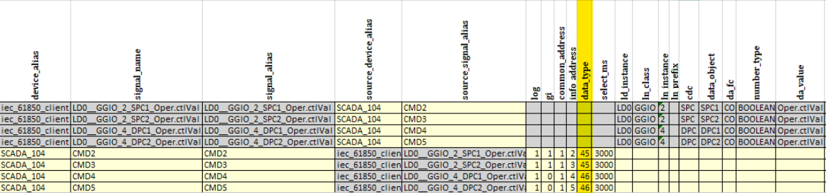](https://wiki.elseta.com/uploads/images/gallery/2023-04/image-1682497120354.png)
##### Double command
Double-command controls are performed towards DPC (controllable double point) IEC 61850 target objects, that is, circuit breakers and controllable disconnector objects. The command can be given with or without a time stamp (C\_DC\_NA\_1, C\_DC\_TA\_1). If time tagged commands are used, it is important to ensure the master and the relay times are synchronized.
Each double-point DPC object has two predefined IEC 60870-5-104 control objects: one intended for direct operation and the other one for select-execute (select-before-operate) operation.
**Double command**
Double-command control operations can be performed towards DPC (controllable double point) data class objects. Direct controls are always possible. Two-step select-execute controls are also possible if the target DPC object allows it. There are two different control objects available for the direct and select-execute alternatives.
• DPC.Oper.ctlVal
Type
ASDU
Control
46
C\_DC\_NA\_1
Double command
Control
59
C\_DC\_TA\_1
Double command with
CP56Time2a
Double command
**Direct operation**
Direct operation is always possible for the double command regardless of the control model (direct or SBO) configured for the target IEC 61850 DPC object. If the control model is SBO, the IEC 60870-5-104 stack automatically performs the two needed operations (select and operate) towards the DPC object.
**Select-execute operation**
A two-step select-and-execute operation is possible only if the target DPC object’s control model is configured as select-before-operate (SBO). For most target DPC objects, the default control model setting mode is SBO. IEC 60870-5-104 selection timeout is defined by the protocol instance’s Selection Timeout setting parameter. When a command is performed from the IEC 60870-5-104 instance, the selection timeout setting configured for the IEC 61850 DPC target object is overridden. Cause of transmission and selected status The relay’s native IEC 61850 data model does not include any cause of transmission (COT) information data. Therefore, monitoring object transmissions from the IEC 60870-5-104 stack can only include the following cause of transmission values.
• 1 = Cyclical
• 3 = Spontaneous
• 20 = General interrogation
• 21...36 = Group 1...16 interrogation
The control command’s response message returned to the controlling client includes COT value 11 = Remote command, but the controlled object value change in monitoring direction is always COT=3 (Spontaneous). While this information is not so important for the controlling client, it can be for another client in a multiple-client environment.# WCC Excel utility
WCC Excel Utility app can be used to:
- Upload configurations to WCC Lite device. App checks if there are no errors in your WCC Lite excel configuration file and converts excel configurations to .json file. Excel file → validation→ .json file.
- Debug various protocols.
- Create IEC 61850 protocol client and server model from .icd, .scd or .cid extensions.
- Create excel configurations for IEC 61850 protocols.
### Connecting WCC Lite
To start using the app you will need to connect your WCC Lite. Fill in *Host, Port, Username, password* and connect as required.
[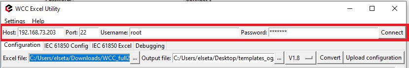](https://wiki.elseta.com/uploads/images/gallery/2023-05/image-1683273653971.png)
- **Host** - an IP address for the device to connect to. (Default value 192.168.1.1)
- **Port** - a PORT number to which an SSH connection can be made; valid values fall into a range between 1 and 65535. (Default is 22)
- **Username** - a username which is used to make an SSH connection. (Default username is root)
- **Password** - a password of a user used for establishing an SSH connection. (Default password is wcclite)
#### Successful connection
If connection is successful a connection status message will appear. Also a bar on the bottom of the app will turn green.
[](https://wiki.elseta.com/uploads/images/gallery/2023-05/image-1683196457098.png)
[](https://wiki.elseta.com/uploads/images/gallery/2023-05/connected.png) Successful connection message
Once connected the app scans your current WCC Litte firmware version and suggest to use a correct conversion version.
[ ](https://wiki.elseta.com/uploads/images/gallery/2023-05/image-1683202961197.png)
If you are using previous WCC Lite firmware versions you could select that from dropdown tab.
WCC Lite firmware selection tab
#### Failed connection
In case connection was not successful a connection status message will appear.
[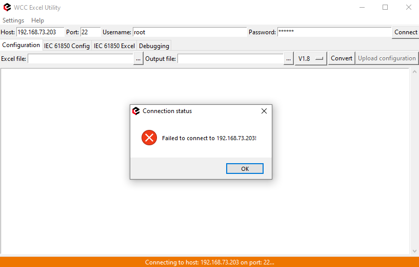](https://wiki.elseta.com/uploads/images/gallery/2023-05/image-1683199782056.png)
Connection failure
Make sure parameters: *Host IP, username and password* you have entered are correct. Note that connection can only be successful if a port used for SSH connection is open for IP address filled in the hostname entry field. Also please check WCC Lite firewall settings in case of connection failure.
### Validate and upload
To make a conversion please select your excel configuration file and press **Convert**. File will go through various validation steps. If there are no errors found in the configuration, the output file should contain the generated configuration, otherwise, an error message is shown to a user.
[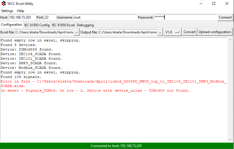](https://wiki.elseta.com/uploads/images/gallery/2023-05/image-1683269177150.png)
Error message indicates where changes need to be made
In order to send a configuration to your WCC Lite press **Upload configuration**. If no errors occur, you should finally be met with text output mentioning configuration has been applied. During the course of the upload process, the aforementioned button is disabled to prevent spanning multiple concurrent processes.
[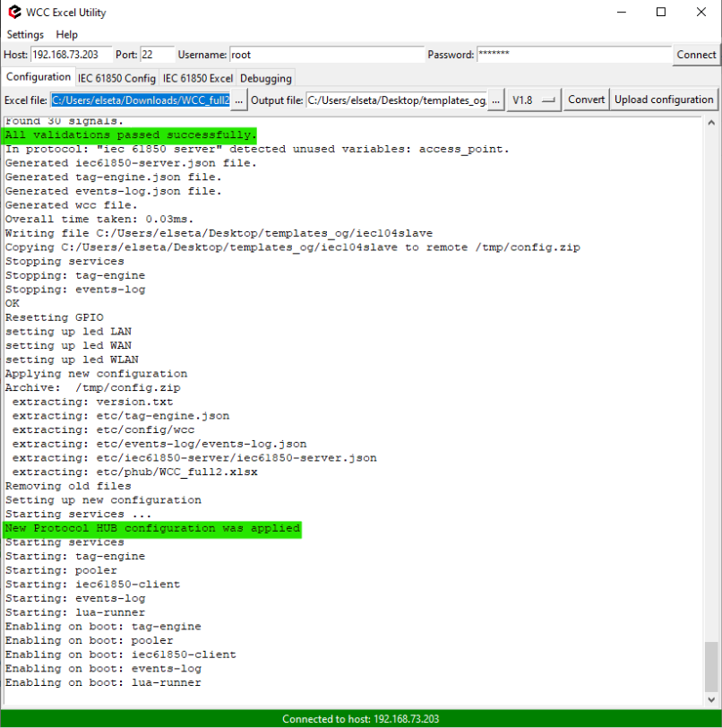](https://wiki.elseta.com/uploads/images/gallery/2023-05/image-1683272332074.png)
Successful upload message
### Configuration
Configuration of IEC61850 for WCCLite is done via WCC Utility. Elseta WCC Utility has two IEC 61850 selections - IEC 61850 Config and IEC 61850 Excel:
- **IEC 61850 Config** is used to create a configuration model file, which IEC 61850 Client service will use to parse reports from the server. IEC 61850 Server is used to send responses to master requests and commands.
- **IEC 61850 Excel** is used to generate excel configuration file which in turn will be used to generated configuration .json via excel-utility.
[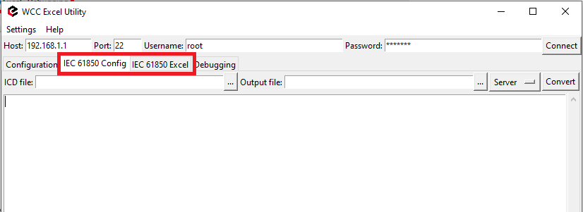](https://wiki.elseta.com/uploads/images/gallery/2023-05/image-1683613769188.png)
WCC Utility with IEC61850 selections
##### Generate model file
To generate IEC 61850 Client or Server model file select “Client” or "Server" in drop down selection tab. Upload file with extensions .icd, .scd or .cid, then select where to output the generated model and press **Convert.**
[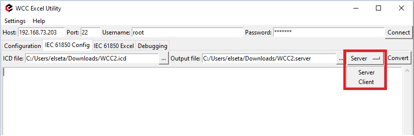](https://wiki.elseta.com/uploads/images/gallery/2023-05/image-1683273244549.png)
Generate IEC 61850 model file
##### Generate excel file
To generate IEC 61850 Client or Server excel file select “Client” or "Server" in drop down selection tab. Upload file with extensions .icd, .scd or .cid, then select where to output the generated file and press **Convert**.
[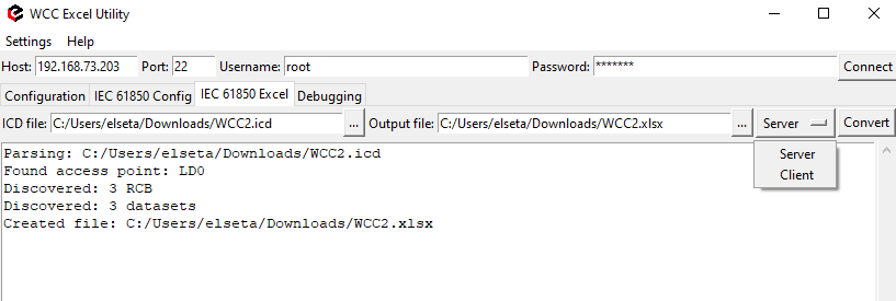](https://wiki.elseta.com/uploads/images/gallery/2023-05/image-1683273424037.png)
Generate IEC 61850 excel file
After generating excel file additional configuration information must be written in the devices sheet:
- A valid host ip address must be provided.
- An authorization method must be provided (if it is a complex authorization method, additional parameters might be required).
- Model filename must be provided. The model filename must be exactly the same as that was generated one step earlier (Model filename can include extension, but it is not mandatory).
[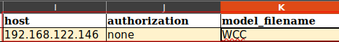](https://wiki.elseta.com/uploads/images/gallery/2023-02/image-1676877418592.png)
Excel configuration (Devices sheet)
### Debugger
WCC excel utility has a debugging tool. This feature helps to track protocol service process and monitor events in real time. If protocol does not work properly (e.g. no communication between devices, data is corrupted, etc.), a user can launch a debug session and find out why the link is not functioning properly
##### Configuration
**Step 1.** Use dropdown menu tab to select a **protocol** you want to debug.
[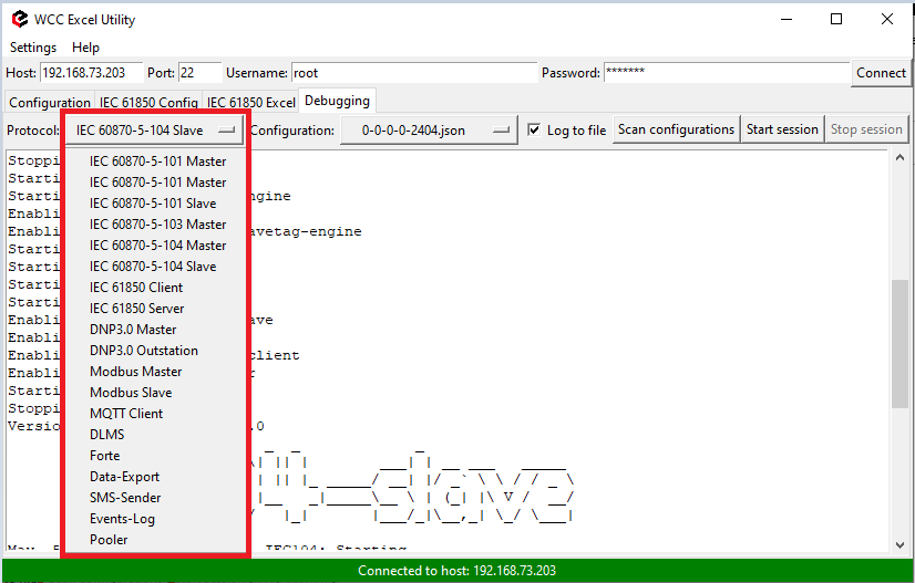](https://wiki.elseta.com/uploads/images/gallery/2023-05/image-1683276901489.png)
Protocol selection tab
**Step 2.** Click on *Scan configurations* to validate protocol.
[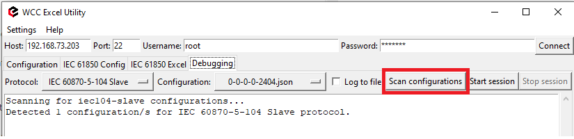](https://wiki.elseta.com/uploads/images/gallery/2023-05/image-1683275032672.png)
Successful protocol validation message
Please note that Debugger only works with protocols that are uploaded to your WCC Lite. If you select a protocol that is not configured on your device an error message will appear. Also you could only debug one protocol at a time.
**Step 3.** Click on *Start session*
##### Debugger logging
There is an option to store debugger log to a file. Thick the box before starting a session.
[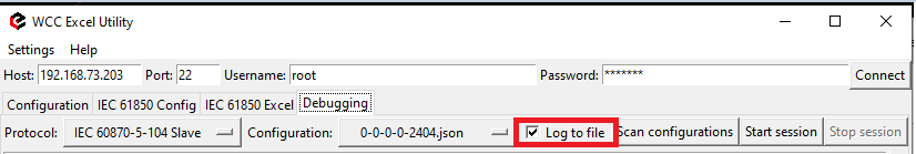](https://wiki.elseta.com/uploads/images/gallery/2023-05/image-1683275243272.png)
In order to change debug logger output file location navigate to *Settings -> Preferences*
[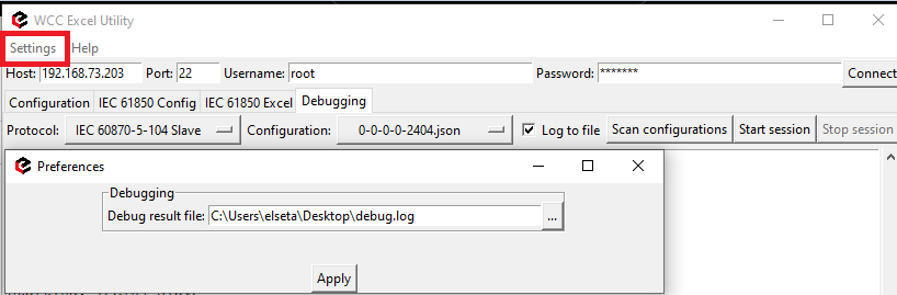](https://wiki.elseta.com/uploads/images/gallery/2023-05/image-1683289151579.png)# Single point to double point and double point to single point information
### Single point to double point information
This example shows how to convert single point information from Modbus RTU to double point information for IEC 60870-5-104.
To begin, open the **Devices** sheet and define two protocols. One row should specify the Modbus RTU master configuration, including which physical port on WCC Lite will be used for communication. Another row should define the IEC104 slave protocol and its network parameters. Make sure all other fields follow the requirements of your setup.
[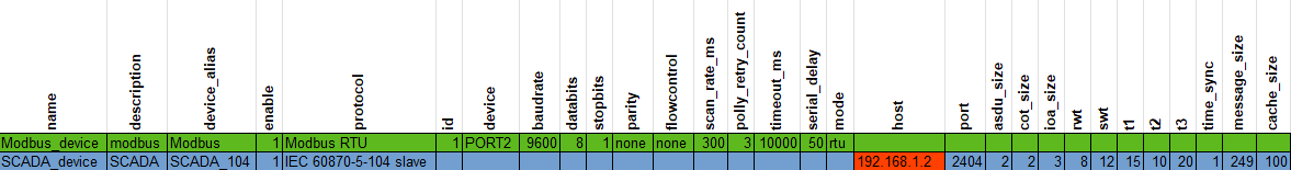](https://wiki.elseta.com/uploads/images/gallery/2025-04/image-1746011615893.png)
In the **Signals** sheet, define two separate Modbus input signals with distinct aliases. These signals will represent the two bits used to build the double point status. Then create a signal for the IEC104 slave with data type 31 ("M\_DP\_TB\_1" Double-point information with time tag). In the source alias field, write both signal aliases separated by a space. This way, both Modbus signals will be used to generate a single double point value.
[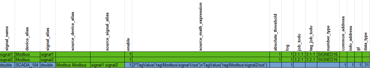](https://wiki.elseta.com/uploads/images/gallery/2025-04/image-1746011643783.png)
To determine the correct double point output, use a source math expression. The following logic is used:
If both signal1 and signal2 are 0, the double point result will be 0.
If both are 1, the result will be 3.
If signal1 is 1 and signal2 is 0, the result will be 2.
If signal1 is 0 and signal2 is 1, the result will be 1.
To test the setup, upload the Excel configuration to WCC Lite. Connect WCC Lite to your computer via Vinci expert (or other RS to USB converter) and run VINCI simulation program. Use one VINCI window configured as IEC104 master. Use a second VINCI window as a Modbus RTU slave. Ensure all settings (e.g. ports, baud rate) match your Excel configuration. Run both simulations and make sure both protocols are connected.
[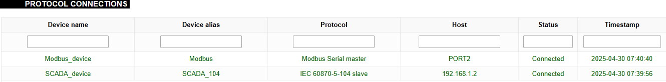](https://wiki.elseta.com/uploads/images/gallery/2025-04/image-1746012517257.png)
[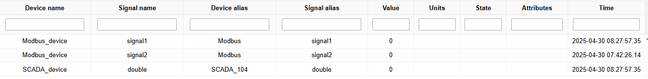](https://wiki.elseta.com/uploads/images/gallery/2025-04/image-1746012014757.png)
On the Modbus slave side, create a tag matching the address used in your configuration. Change the tag value to trigger a change in double point state, and observe the corresponding updates in the IEC104 master tab or web interface
[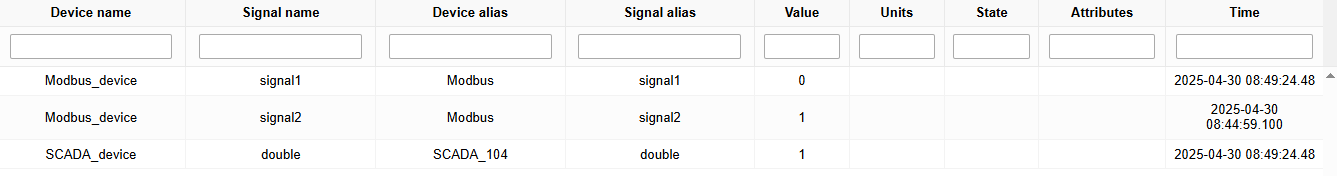](https://wiki.elseta.com/uploads/images/gallery/2025-04/image-1746013309438.png)[](https://wiki.elseta.com/uploads/images/gallery/2025-04/image-1746013293609.png)
[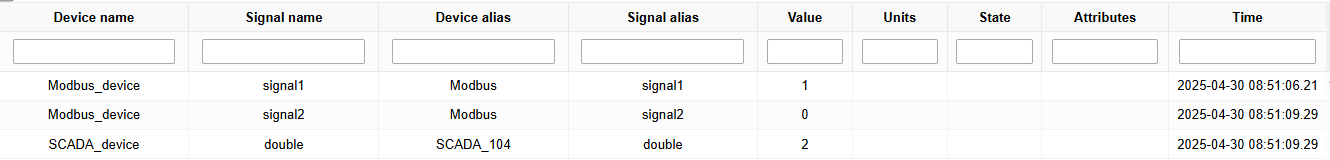](https://wiki.elseta.com/uploads/images/gallery/2025-04/image-1746013424280.png)[](https://wiki.elseta.com/uploads/images/gallery/2025-04/image-1746013404660.png)
[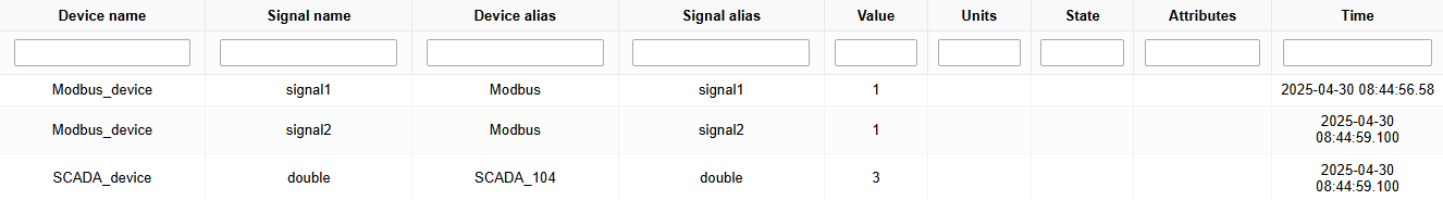](https://wiki.elseta.com/uploads/images/gallery/2025-04/image-1746013253645.png)
[](https://wiki.elseta.com/uploads/images/gallery/2025-04/image-1746013226134.png)
## Double point to single point information
This example demonstrates how to convert double point information from IEC 60870-5-104 to single point data for Modbus RTU.
Begin with the **Devices** sheet. One row should define the IEC104 slave using the appropriate port and the IP address of the host computer. Another row should define the Modbus RTU master, specifying which physical port on WCC Lite will be used for communication. Make sure all protocol parameters are correctly set.
[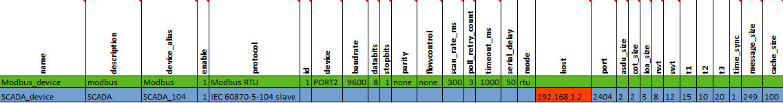](https://wiki.elseta.com/uploads/images/gallery/2025-04/image-1746014021584.png)
Open the **Signals** sheet. Define a Modbus signal using a function 1 (read discrete output coils). Then define a double point signal with data type 31 ("M\_DP\_TB\_1" Double-point information with time tag) for the IEC104 protocol. Set the source alias to the Modbus signal you just created.
[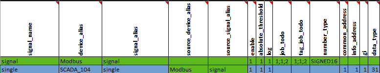](https://wiki.elseta.com/uploads/images/gallery/2025-04/image-1746015633133.png)
WCC Lite will interpret the double point values and convert them to single point logic.
**Value**
**State**
00
indeterminate
01
off
10
on
11
indeterminate
To simulate this setup, upload your configuration file to WCC Lite. Connect WCC Lite to your computer via Vinci expert (or any other RS to USB converter) and run VINCI simulation program. Start two simulations. One should act as the IEC104 master. The second should be a Modbus RTU slave, connected to the VINCI Expert port. Ensure all settings (e.g. ports, baud rate) match your Excel configuration. Run both simulations and make sure both protocols are connected.
[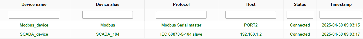](https://wiki.elseta.com/uploads/images/gallery/2025-04/image-1746015978156.png)
On the Modbus slave side, create a tag matching the address used in your configuration. Change the tag value to trigger a change in double point state, and observe the corresponding updates in the IEC104 master tab or web interface.
If Value box is checked, it means that this value is 1. Change tag values accordingly and observe the results on the web and IEC104 master tab:
[](https://wiki.elseta.com/uploads/images/gallery/2025-04/image-1746016295303.png)[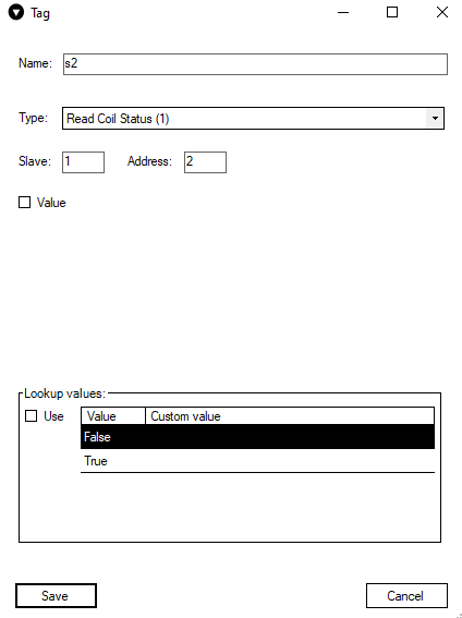](https://wiki.elseta.com/uploads/images/gallery/2025-04/image-1746015515780.png) [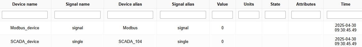](https://wiki.elseta.com/uploads/images/gallery/2025-04/image-1746016001204.png)
[](https://wiki.elseta.com/uploads/images/gallery/2025-04/image-1746016065227.png)
[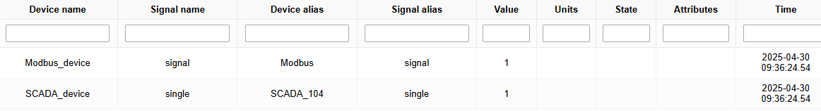](https://wiki.elseta.com/uploads/images/gallery/2025-04/image-1746016116567.png)
[](https://wiki.elseta.com/uploads/images/gallery/2025-04/image-1746016136836.png)
[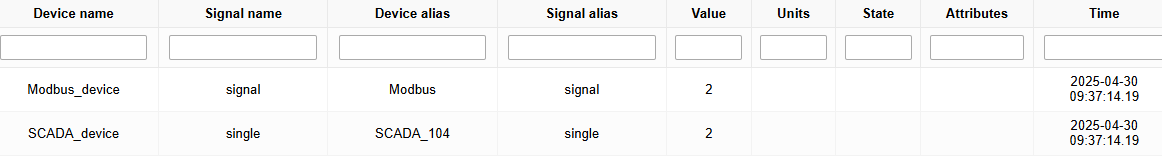](https://wiki.elseta.com/uploads/images/gallery/2025-04/image-1746016177454.png)
[](https://wiki.elseta.com/uploads/images/gallery/2025-04/image-1746016166017.png)
[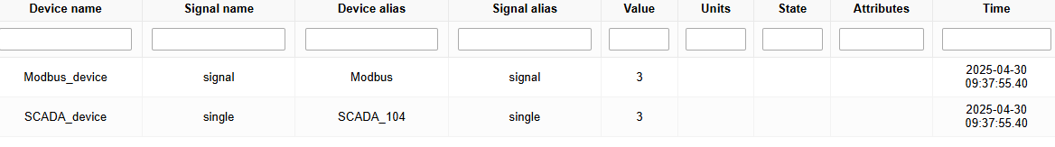](https://wiki.elseta.com/uploads/images/gallery/2025-04/image-1746016202898.png)
[](https://wiki.elseta.com/uploads/images/gallery/2025-04/image-1746016216124.png)
Configurations:
Single point to double point --> [Download](https://wiki.elseta.com/attachments/663)
Double point to single point --> [Download](https://wiki.elseta.com/attachments/664)# Firmware 1.5 and 1.8 configurations comparison
## Description
Since 1.5 firmware version some configuration parameters stopped existing, new ones were added, others simply changed their name. All these changes might be a problem when you want to import old configuration file into WCC Lite with a new firmware. This article is aimed to provide differences between different firmware versions for such protocols as Modbus Master, IEC 608705103 Master and Internal Data.
## MODBUS Master
#### **Device sheet:**
**Parameter**
**1.5**
**1.8**
mode
-
+
ascii
+
-
keep\_alive\_timeout
-
+
event\_history\_size
+
-
update
-
+
\+ (exists)
\- (does not exist)
**Description of a Parameter**
**1.5**
**1.8**
**Parameter**
**Parameter**
IP address of TCP slave device
host
ip
Number of requests, before link is considered lost (device status signals are
changed) and reconnect attempt will be issued
poll\_retry\_count
retry\_count
RS485 delay between read and write operations in milliseconds
poll\_delay\_ms
serial\_delay
#### **Signal sheet:**
**Parameter**
**1.5**
**1.8**
scan\_rate\_ms
+
-
\+ (exists)
\- (does not exist)
**Description of a Parameter**
**1.5**
**1.8**
**Parameter**
**Parameter**
Size of this signal’s log in Event log.
log\_size
log
## IEC 608705103 Master
#### **Device sheet:**
**Parameter**
**1.5**
**1.8**
event\_history\_size
+
-
serial\_delay
+
-
retry\_delay\_ms
-
+
\+ (exists)
\- (does not exist)
**Description of a Parameter**
**1.5**
**1.8**
**Parameter**
**Parameter**
Polling interval in milliseconds. Time frame between two telegrams from master.
poll\_interval\_ms
scan\_rate\_ms
Response timeout in milliseconds
poll\_timeout\_ms
timeout\_ms
Number of retries of failed requests before announcing that device is in Error state
poll\_retry\_count
retry\_count
#### **Signal sheet:**
**Description of a Parameter**
**1.5**
**1.8**
**Parameter**
**Parameter**
Size of this signal’s log in Event log.
log\_size
log
## WCC Lite internal signals
#### **Device sheet:**
# SNMP
### Description
This article describes installing, setting up and monitoring SNMP with WCC Lite.
### Install
To install SNMP to the WCC Lite you need to download .ZIP archive that has all the files necessary -> [SNMP\_tutorial.zip](https://wiki.elseta.com/attachments/616)
Now you need to extract the .ZIP file. You will get a folder called *SNMP tutorial*. Go inside it and you will find these files:
[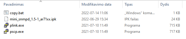](https://wiki.elseta.com/uploads/images/gallery/2022-07/image-1657786127981.png)
The next step is to ensure that the WCC Lite is reachable by your computer, you can do it in many ways. One of them is to connect it to your PC via ethernet cable to the WCC Lite ETH0.
After making sure there is a connection you can test it by opening your internet browser and entering the IP of the WCC Lite. If you have the default settings and WCC Lite is connected to your PC via an ethernet cable, then the IP is **192.168.1.1**
Now you can open the **copy.bat** file. It will ask for the IP of the WCC Lite at first, enter the IP. Next is the username and password. If the defaults are left, the username will be **root** and password - **wcclite**.
Your command window should look like this:
[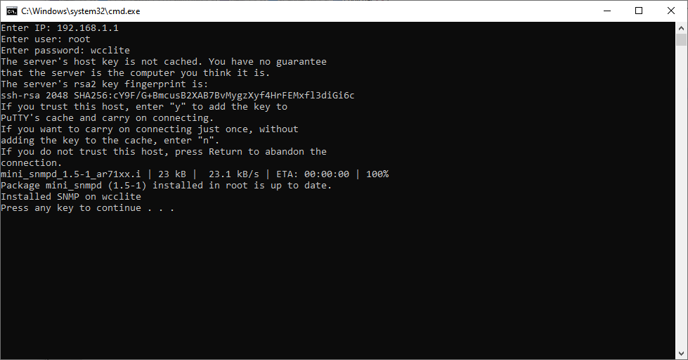](https://wiki.elseta.com/uploads/images/gallery/2022-07/image-1657787503476.png)
After installing you exit the command line and the SNMP is installed on your device.
The WCC Lite .MIB file can be downloaded from here -> [ELSETA-WCCLITE-MIB.mib](https://wiki.elseta.com/attachments/37)
The next step is to download a SNMP trap watcher program. For this example we are going to use MIB Browser, which can be downloaded from here -> [MIB browser setup.exe](https://wiki.elseta.com/attachments/551)
After installing the program you will need to upload the downloaded [ELSETA-WCCLITE-MIB.mib](https://wiki.elseta.com/attachments/37) file to the MIB Browser:
[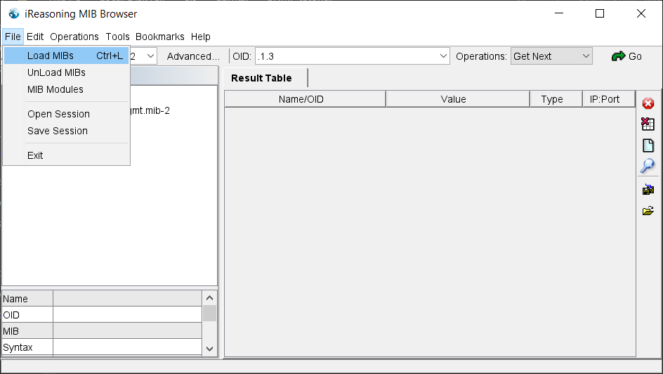](https://wiki.elseta.com/uploads/images/gallery/2023-08/image-1692691690384.png)
### Setting up
Now you will need to allow the telemetry agent service on WCC Lite to send the core data about the device resources' usage. Server address is your computer's IPv4 address. The usual port for SNMP is **162**. Set the sending period as needed and press Save & Apply. The screen should look something like this:
[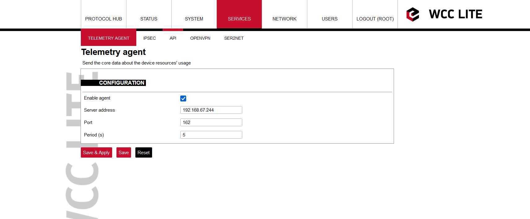](https://wiki.elseta.com/uploads/images/gallery/2023-08/image-1692690481929.png)
After setting up the Telemetry agent tab navigate to Network -> Firewall -> Traffic rules. Enable the Allow-SNMP packet and edit the destination port to match the one in Telemetry agent screen (for this example it is 162):
[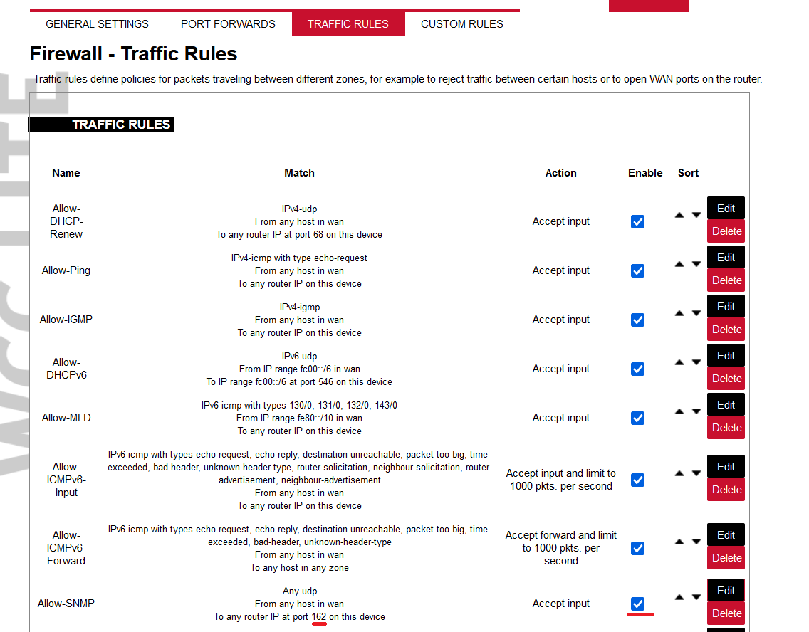](https://wiki.elseta.com/uploads/images/gallery/2023-08/image-1692692627444.png)
Next step is to change the port to 162 in the installed mini\_snmpd on WCC Lite. You can do that via the Ubuntu terminal. Log into WCC Lite by typing in **ssh root@192.168.1.1** . The password is **wcclite** . Now type **/usr/bin/mini\_snmpd -h** and after pressing enter you will see this screen:
[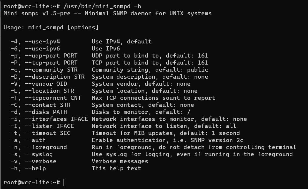](https://wiki.elseta.com/uploads/images/gallery/2023-08/image-1692698709618.png)
Now you will need to type in these commands: **/usr/bin/mini\_snmpd -p 162** and **/usr/bin/mini\_snmpd -P 162** to change the port to 162.
[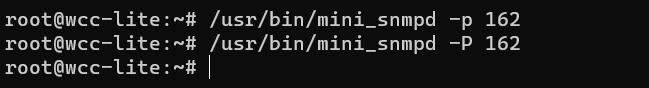](https://wiki.elseta.com/uploads/images/gallery/2023-08/image-1692698977130.png)
After these changes you can now go back to the MIB Browser program and change the address to the IP you used while connecting to WCC Lite web. For example:
[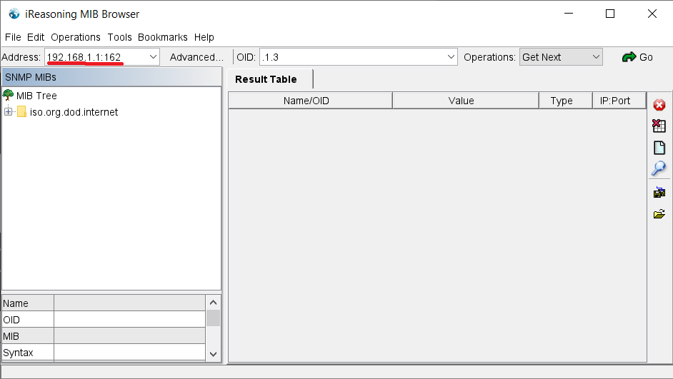](https://wiki.elseta.com/uploads/images/gallery/2023-08/image-1692699624139.png)
### Monitoring
If no errors occurred you should be able to monitor the data about WCC Lite resources' usage with SNMP. For example, by pressing right click on the *private* folder and pressing the Walk option, you will see the window bellow, which represents the result table of resource usage.
[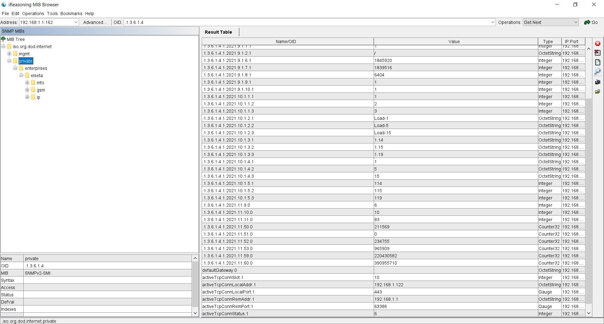](https://wiki.elseta.com/uploads/images/gallery/2023-08/image-1692703270166.png)
The given [ELSETA-WCCLITE-MIB.mib](https://wiki.elseta.com/attachments/37) contains an old version, so as of now, the results might not be accurate or they may not show at all. Update of the MIB file is needed.
# M-Bus Serial Communication Setup Guide
### Description
This article describes how to establish communication between WCC Lite and a meter using the Meter-Bus protocol.
### Physical Link Setup: WCC Lite to Meter Connection
Set up your computer and connect Ethernet cable to WCC Lite ETH0 port. Login with default credentials and setup basic required settings (name, network, users, etc. ). You can find configuration tutorials in [How to](https://wiki.elseta.com/books/how-to) articles.
[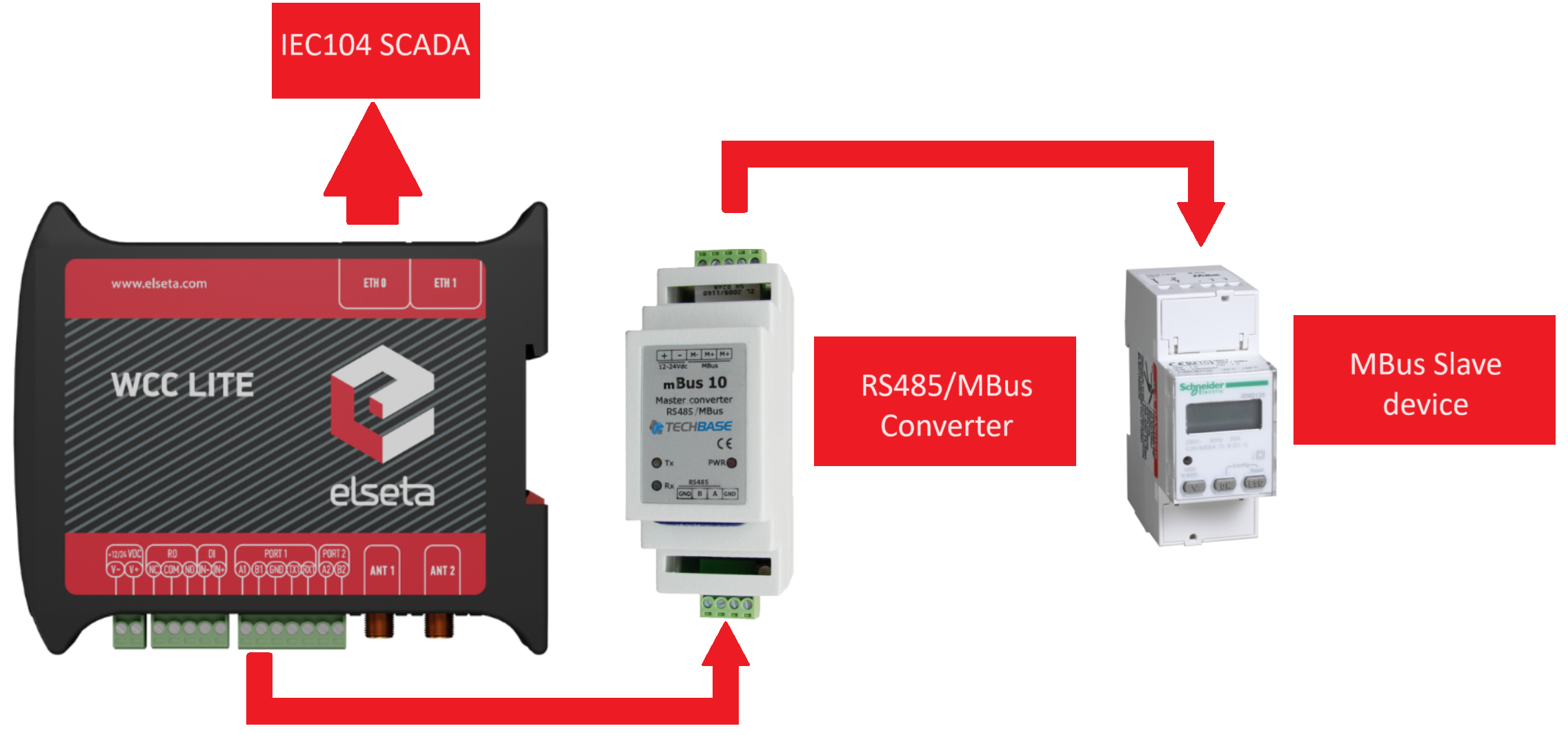](https://wiki.elseta.com/uploads/images/gallery/2023-12/pav-wcc.png)
The WCC Lite lacks a built-in hardware interface for M-Bus connectivity, requiring the use of an RS485 or RS232 to M-Bus Master Converter for establishing a connection.
In the illustrated example, a Schneider IEM2135 meter was used alongside the M-Bus 10 RS485/M-Bus Master Converter for data exchange.
#### Example
When the meter configuration parameters match the ones in the Excel sheet, communication can be established. In the example, we also set up IEC104\_SCADA communication along with M-Bus for smooth integration with the IEM2135 meter.
Configuration for the example showed in the illustration -> [Download](https://wiki.elseta.com/attachments/574)
The guidelines for creating your own configuration will be presented in the following segment.
### Configuration
##### M-Bus parameters for *Device* tab
**Parameter**
**Type**
**Description**
**Required
**Default value**
(when not specified)
**Range**
Min
Max
name
string
User-friendly device name
Yes
description
string
Description of a device
No
device\_alias
string
Alphanumeric string to identify a device
Yes
enable
boolean
Enabling/disabling a device
No
1
0
1
protocol
string
Protocol to be used.
Yes
mbus serial
scan\_rate\_ms
integer
All reads and writes will be executed within the timeframe in milliseconds.
No
10000
poll\_delay\_ms
integer
Minimum time delay in milliseconds to wait
before sending any data on port.
No
200
timeout\_ms
integer
Timeout of waiting for an incoming response in milliseconds
Tag job as single or multiple comma-separated OBIS codes
Yes
tag\_job\_todo
string
Tag sub job
Yes
Optional parameters for signals are available on this page -> [Optional parameters for signals](https://wiki.elseta.com/books/manual/page/182-optional-parameters-for-signals).
If you wish to include mathematical expressions in your signals, the guidelines can be found on this page -> [Mathematical functions](https://wiki.elseta.com/books/manual/page/183-mathematical-functions).
### Debugging
If M-Bus does not work properly (e.g. no communication between devices, data is corrupted, etc.), a user can launch a debug session from command-line interface and find out why the link is not functioning properly.
On the web interface's protocol connections page, M-bus devices will not be displayed. If the connection is established correctly, it can be observed on the imported signals page.
To launch a debugging session, a user should stop the *pooler* process and run the *pooler* command with respective flags.
- Step 1: Open the command terminal on your computer.
- Step 2: Connect via SSH, example of the command **ssh root@192.168.1.1** and then enter your designated password.
- Step 3: Service must be stopped by entering the following command into the wcclite:
**/etc/init.d/pooler stop**
- Step 4: After service is stopped it must be started with the preferred configuration file (JSON
files found in /etc) and a debug level 7: **pooler -c /etc/pooler/pooler.json -d7**
- Step 5: Once the problem is diagnosed normal operations can be resumed with the following command: **/etc/init.d/pooler start**
##### POOLER command line debugging options
```
-h [ ––help ] Display help information -V [ ––version ] Show version -d Set debugging level -c [ ––config ] Config path -s [ ––serial ] Show serial port data -r [ ––raw ] Show raw telegram data -B [ ––mbus ] Show M-Bus driver output
```
One example of debugging involves using the following command -> **pooler -c /etc/pooler/pooler.json -B -d7 -s**.
In this mode, both request packets and received packets are visible, along with the M-Bus driver output showing translated signal values received. This information can be instrumental in determining the correct configuration for the signal sheet. Additionally, messages regarding incorrect M-Bus frames can be observed, aiding in identifying potential wiring mistakes.# Add ssh-key
#### Functionality
The SSH key functionality in the WCC Lite device allows you to authenticate securely without needing to enter a password each time you access the device via SSH. This method uses public-key cryptography to ensure a secure connection.
This feature enables you to paste public SSH keys into the provided interface, granting access to users whose private keys match the uploaded public keys. This enhances security and simplifies the login process.
The add SSH key functionality was implemented in WCC Lite starting from firmware version v1.9.3.
### Generating SSH Keys
To use this functionality, you first need to generate an SSH key pair on your local machine. Here are the steps for generating a key pair:
1\. **Open a terminal window**.
2\. **Run the following command**:
```sh
ssh-keygen
```
3\. **Follow the prompts**:
- You will be asked to enter a file in which to save the key. Press Enter to accept the default location.
- Enter a passphrase for additional security, or leave it empty for no passphrase
[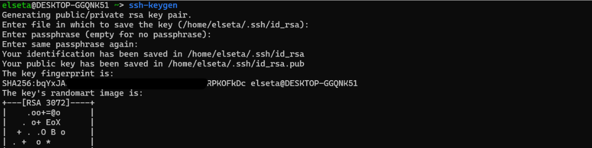](https://wiki.elseta.com/uploads/images/gallery/2024-07/image-1721655057265.png)
4\. The generated keys will be saved in the `.ssh` directory in your home folder. The public key will be named `id\_rsa.pub` and the private key `id\_rsa`.
### Adding the Public Key to the WCC Lite Device
1\. Copy the content of your public key**:**
```
cat ~/.ssh/id_rsa.pub
```
[](https://wiki.elseta.com/uploads/images/gallery/2024-07/image-1721721321085.png)
2\. Access the WCC Lite web interface and navigate to the SSH-KEYS section. *System -> Administration*
[](https://wiki.elseta.com/uploads/images/gallery/2024-07/image-1721653963899.png)
3\. Paste the copied public key into the text box provided. Ensure that each key is on a new line if you are adding multiple keys.
[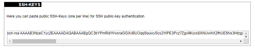](https://wiki.elseta.com/uploads/images/gallery/2024-07/image-1721654024569.png)
4\. Save the changes to apply the new keys.
[](https://wiki.elseta.com/uploads/images/gallery/2024-07/image-1721653982535.png)
### Using the SSH Key for Authentication
After adding the public key to your WCC Lite device, you can now authenticate using the corresponding private key without entering a password.
1\. Open a terminal window.
2\. Use the SSH command to connect to your device:
```
ssh root@192.168.1.1
```
Replace `root` with the username (which is `root` in this case) and `192.168.1.1` with the IP address of your WCC Lite device.
You should now be able to access the WCC Lite device securely and conveniently using your SSH key pair.# Data Export
### Introduction
This article describes how to configure Wcc Lite to export data to external servers step by step.
Data export functionality is available since firmware version v1.5.0, of WCC Lite.
[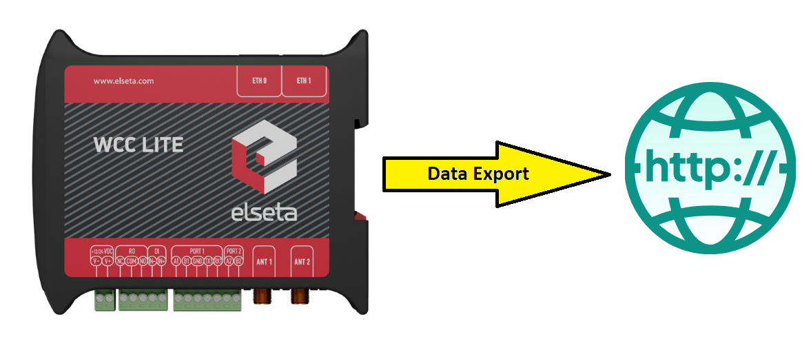](https://wiki.elseta.com/uploads/images/gallery/2024-09/gCcdata-export.png)
Fig. 1 Wcc Lite's gathered data export to external server
### First step: Configuring the Devices sheet of excel configuration
To fully configure the "Data Export" device and it's signals, user can use the tables provided in the manual of Wcc Lite -> [Data Export section](https://wiki.elseta.com/link/1215#bkmrk-data-export-%28data-ex) or use the tables below in this article. Important to notice that some parameters to declare the Data Export device and it's signals are required and some of them are optional. In this article we will mainly use the required ones and a few of the optional parameters, to reach the desired outcome of signals exporting. Also, some parameters has default values, even if the parameters are not required, so please make sure that the default value is the same as needed, otherwise change it to the correct one from the available choices and describe it in excel configuration.
*Data export (data-export) parameters for Devices tab table:*
**Parameter**
**Type**
**Description**
**Required
**Default value**
(when not specified)
**Range**
Min
Max
name
string
User-friendly device name
Yes
device\_alias
string
Device alias to be used in configuration
Yes
enable
boolean
Enabling/disabling of a device
No
1
0
1
protocol
string
Selection of protocol
Yes
Data Export
timeout
integer
The time frame during which transmission to the remote server has to be completed (**in seconds**)
The same symbols cannot be selected for both csv\_field\_separator and csv\_decimal\_separator. In such case both of them will be set to default values ”.” and ”,” respectively.
The data generation rate may be going to be bigger than what the data buffer can hold (controlled by *records\_buffer\_size* and *logging\_period\_sec*). To make sure that no data loss occurs there’s an additional data logging call made in case the data buffer reaches a *records\_buffer\_size* value.
For this example configuration, the Wcc Lite's template configuration for IOMod 8AI Modbus RTU protocol is being used. Simply in Devices sheet add the information required for Data Export service. As it can be seen in **Fig. 2** to declare the Data Export device in Devices sheet a few parameters were used: ***name**, **description**, **device\_alias**, **enable**, **protocol**, **type**, **upload\_rate\_sec**, **record\_buffer\_size**, **timestamp*** and ***host***.
[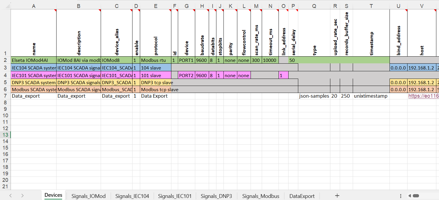](https://wiki.elseta.com/uploads/images/gallery/2024-09/image-1727685097922.png)
Fig. 2 Describing the Data Export service in Devices sheet of excel configuration
#### Host URL format rules
The parameter host is highly configurable and might contain a considerable amount of information:
• *Protocol* - FTP or HTTP (encrypted and encrypted);
• *URL address* - both resolved and non-resolved;
• *Authentication* - pair of users and/or passwords;
• *Port* - useful when non-standard value is used;
• *Endpoint* - a place in the server to which a call is made
The format for the host parameter can be summarized as:
`[ h t t p ( s ) / f t p ( s ) ] : / / [ [ u s e r ] : [ p a s s w o r d ]@] [ URL ] [ : p o r t ] / [ e n d p o i n t ]`
Options are printed in square brackets. A protocol has to be selected, otherwise HTTP will be used as a default. The user and password pair is optional, but if the user: password pair is used, it should proceed with the @ sign.
HTTP and FTP use default or user-assigned ports. By default HTTP uses port 80, while HTTPS uses port 443, FTP sends data over port 21, FTPS - over port 990. Make sure that these ports are open in the firewall on both the server and client side, otherwise, data will not be sent successfully.
Finally, a POST request (for HTTP) or upload (for FTP) can be made to a specific place (endpoint). This endpoint should be described after a URL and port (if used).
### Second step: Configuring the DataExport sheet of excel configuration
Signals to be sent are configured differently than signals for most other protocols. As data export service only transmits signals and does no data processing, usual signal logic is not used for them. That means that:
• Signals for data export service are not seen in the *Imported Signals* tab;
• Signals for data export service are configured in a different Excel sheet called DataExport
The parameters to be filled in the DataExport sheet are shown in the table below.
*Data export (data-export) parameters for the DataExport tab*
**Parameter**
**Type**
**Description**
**Required
**Default value**
(when not specified)
**Range**
Min
Max
device\_alias
string
Device alias to be used in configuration Yes
Yes
device\_name
string
User-friendly device name as in the Device sheet
Yes
tag\_name
string
User-friendly signal name
Yes
source\_device\_alias
string
device\_alias of a source device
Yes
source\_signal\_alias
string
source\_alias of a source signal
Yes
enable
boolean
Enabling/disabling of a measurement to be transmitted and logged
No
1
0
1
attribute
string
An additional attribute to be attached to a signal
No
To configure Wcc Lite to export data to an external server user must declare the signals for every measurement that needs to be exported, as well as describe the device (Data Export) in Devices sheet. This is done simply by linking signals from other protocols to the signals declared for exporting data. In **Fig. 3** it is shown how measurements from IOMod 8AI (Signals\_IOMod sheet ***device\_alias*** and ***signal\_alias***) are linked to the signals (DataExport sheet ***source\_device\_alias*** and ***source\_signal\_alias***) that will be exported to the server, which is declared as "Host" parameter in Devices sheet of excel configuration.
[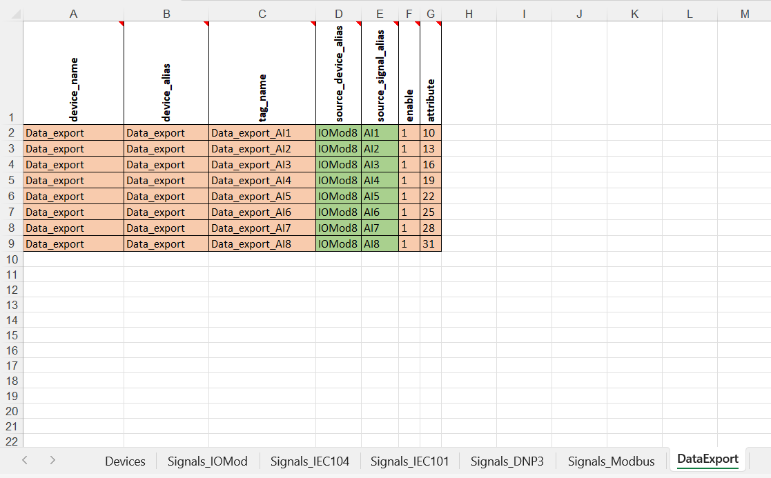](https://wiki.elseta.com/uploads/images/gallery/2024-09/image-1727679471995.png)
Fig. 3 Linking of the measurements from IOMod 8AI to Data Export signals
### Data representation in HTTP(S) server
First thing to mention, that if user wants to export the data to an external server, the Wcc Lite should have access to the internet. This is done simply by connecting Wcc Lite's ETH1 port to the Ethernet port of the internet router.
[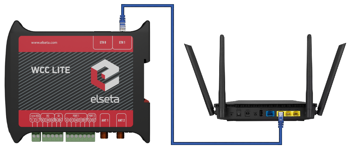](https://wiki.elseta.com/uploads/images/gallery/2024-09/image-1727692655347.png)
Fig. 4 Wcc Lite's ETH1 port connected to the internet router for internet access
For the representation of data in HTTP(S) or FTP(S) servers, user can use one of the available servers that can be found online. In this specific example Pipedream.com online HTTP server was used. When registered to the site, generate the URL for the server. This URL can be seen in example configuration Devices tab "host" parameter for Data Export device (*https://eo1167h7o8m7ur6.m.pipedream.net).* When the communication between Wcc Lite and IOMod is normal, and Wcc Lite is gathering measurements through Modbus RTU protocol, these measurement, as described before, are linked to Data Export signals. These signal values then are exported to the predefined HTTP(S) server in a defined file format.
On the Pipedream.com online server a POST request (for HTTP) is being done and the data has been exported to it. As it can be seen in the **Fig. 5**, first URL is the same as the one declared in "Host" parameter for the Data Export service. Then the File and it's name, where the gathered data is being put and the URL on the bottom to download this file. How these measurements are represented in json\_samples format can be seen in **Fig. 6** and in the *tag-log-1727347342174741-322120016.json* file on the bottom of this article. Also to see other file formats for exported data please check [Data Export](https://wiki.elseta.com/link/1215#bkmrk-format-of-exported-d) article in Wcc Lite manual.
[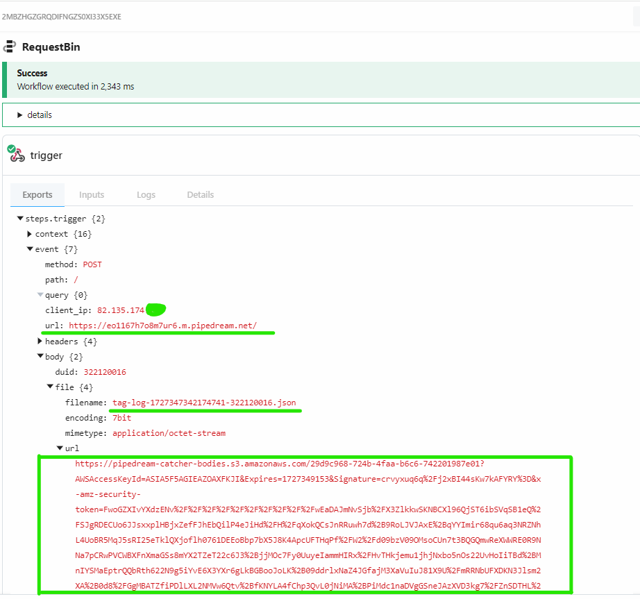](https://wiki.elseta.com/uploads/images/gallery/2024-09/image-1727694123312.png)
Fig. 5 Information in Pipedream.com HTTP server about the data packet exported from Wcc Lite
[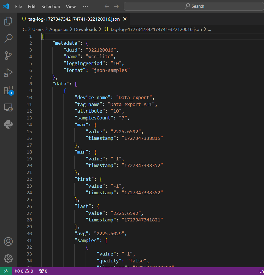](https://wiki.elseta.com/uploads/images/gallery/2024-09/image-1727695036056.png)
Fig. 6 Measurements exported in json-samples format
##### Files used in this article:
1\. [IOMod8AI\_data\_export.xlsx](https://wiki.elseta.com/attachments/621)
[2. tag-log-1727347342174741-322120016.json](https://wiki.elseta.com/attachments/620)# Enable Ser2net on WCC Lite
Ser2net is a service available on WCC Lite that allows you to bridge serial ports over a TCP/IP network. This is particularly useful when you need to access or configure serial devices remotely. One common use case is remote configuration of Elseta v2 IOMod devices using the [IOMod Utility application](https://wiki.elseta.com/books/tools-and-software/page/iomod-utility).
To access the Ser2net settings, open your web browser and log in to the WCC Lite web interface. Navigate to the **Services** section and select **Ser2net**. Once there, choose either **PORT1** or **PORT2** from the dropdown menu, depending on which physical port your IOMod is connected to. After selecting the desired port, simply click the **Enable** checkbox to activate the service (Fig. 1)
Fig. 1 WCC Lite web interface Ser2net page view
Unlike traditional serial setups, there's no need to configure baud rate, parity, or other serial communication parameters when using Ser2net with the IOMod Utility. The IOMod Utility handles communication automatically, making the setup process straightforward and reliable.
Before using Ser2net, ensure that the necessary firewall traffic rule is enabled to allow incoming TCP connections. This step is required for remote tools like the IOMod Utility to connect through the network. You can configure this rule in the **Network** → **Firewall** section under the **Traffic Rules** tab, where you can either enable a pre-existing rule or create a custom one to allow access to the specific TCP port used by Ser2net. Tick the checkbox (Fig. 2), then click **Save & Apply** at the bottom of the page.
Fig. 2 WCC Lite web interface Traffic rules page view# Firmware 1.7.0 and 1.11 configurations comparison
## Description
This document summarizes configuration differences between WCC Lite firmware versions 1.7.0 and 1.11. Each protocol section contains two separate tables: one for Device Sheet and one for Signal Sheet, following the original documentation structure.
(-) indicates that parameter does not exist
(+) indicates that parameter exists
## MODBUS Master
#### **Signal sheet:**
**Parameter**
**1.7.0**
**1.11**
**Description**
Periodic\_update\_ms
-
+
Signal value will be published periodically according to the value set.
## MODBUS Slave
#### **Device sheet:**
**Parameter**
**1.7.0**
**1.11**
**Description**
Respond\_delay
-
+
Time in milliseconds to wait before sending responses. Disabled if the value is set to 0
#### **Signal sheet:**
**Parameter**
**1.7.0**
**1.11**
**Description**
periodic\_update\_ms
-
+
Signal value will be published periodically according to the value set.
## DNP3.0 Master
#### **Device sheet:**
**Parameter**
**1.7.0**
**1.11**
**Description**
ip
host
ip
use\_local\_time
-
+
If enabled (1), communication uses system time instead of UTC.
## DNP3.0 Slave
#### **Device sheet:**
**Parameter**
**1.7.0**
**1.11**
**Description**
Control\_code
-
-
DNP3 control model code of CROB signal. TripClose and Pulse control model requires **PulseOn/off** times to be set
Pulse\_on\_time\_ms
-
-
Pulse ON time in milliseconds, when using Pulse or TripClose control models must be set
Pulse\_off\_time\_ms
-
-
Pulse OFF time in milliseconds, when using Pulse or TripClose control models must be set
## IEC 101 Master
#### **Device sheet:**
**Parameter**
**1.7.0**
**1.11**
**Description**
broadcast\_timesync
-
+
Enables or disables broadcast time sync. If 0 - disabled; if 1 - enabled.
#### **Signal sheet:**
**Parameter**
**1.7.0**
**1.11**
**Description**
periodic\_update\_ms
-
+
Signal value will be published periodically according to the value set.
tag\_job\_todo
-
+
tag\_job\_todo value must be: communication\_status. If the signal returns 1 – connection is OK; if 2 – disconnected.
## IEC 101 Slave
#### **Signal sheet:**
**Parameter**
**1.7.0**
**1.11**
**Description**
periodic\_update\_ms
-
+
Signal value will be published periodically according to the value set.
Select\_ms
-
+
Polling interval in milliseconds. The time frame between two telegrams from the master.
tag\_job\_todo
-
+
tag\_job\_todo value must be: communication\_status. If the signal returns 1 – connection is OK; if 2 – disconnected.
## IEC 103 Master
#### **Device sheet:**
**Parameter**
**1.7.0**
**1.11**
**Description**
reset\_command\_type
-
+
The user can choose the reset command type between FCB and CU.
#### **Signal sheet:**
**Parameter**
**1.7.0**
**1.11**
**Description**
periodic\_update\_ms
-
+
Signal value will be published periodically according to the value set.
tag\_job\_todo
-
+
tag\_job\_todo value must be: communication\_status. If the signal returns 1 – connection is OK; if 2 – disconnected.
## IEC 104 Master
#### **Device sheet:**
**Parameter**
**1.7.0**
**1.11**
**Description**
ip
host
ip
Slave device IP
#### **Signal sheet:**
**Parameter**
**1.7.0**
**1.11**
**Description**
periodic\_update\_ms
-
+
Signal value will be published periodically according to the value set.
tag\_job\_todo
-
+
tag\_job\_todo value must be: communication\_status. If the signal returns 1 – connection is OK; if 2 – disconnected.
## IEC 104 Slave
#### **Signal sheet:**
**Parameter**
**1.7.0**
**1.11**
**Description**
periodic\_update\_ms
-
+
Signal value will be published periodically according to the value set.
tag\_job\_todo
-
+
tag\_job\_todo value must be: communication\_status. If the signal returns 1 – connection is OK; if 2 – disconnected.
## IEC 61850 Server
#### **Device sheet:**
**Parameter**
**1.7.0**
**1.11**
**Description**
Tls
+
-
Edition
+
-
auth
-
+
Authorization type
authorization
+
-
## IEC 61850 Client
#### **Device sheet:**
**Parameter**
**1.7.0**
**1.11**
**Description**
ip
host
ip
auth
-
+
Authorization type
authorization
+
-
event\_history\_size
+
-
model\_filename
-
+
The filename of the client model uploaded to WCC (must contain .client extension)
## MQTT
#### **Device sheet:**
**Parameter**
**1.7.0**
**1.11**
**Description**
ip
host
ip
auth
-
+
Authorization type
Ca\_certificate
-
+
Certificate authority file for TLS connection
Client\_certificate
-
+
Client certificate file for TLS connection
Client\_key
-
+
The private key that corresponds to the client certificate for TLS connection
Client\_id
-
+
User-friendly name for client ID
#### **Signal sheet:**
**Signal**
**1.7.0**
**1.11**
**Description**
periodic\_update\_ms
-
+
Signal value will be published periodically according to the value set.
## DLMS/COSEM
#### **Device sheet:**
**Parameter**
**1.7.0**
**1.11**
**Description**
poll\_delay\_ms
+
-
Minimum time delay in milliseconds to wait before sending any data on port.
## IEC 62056-21
#### **Device sheet:**
**Parameter**
**1.7.0**
**1.11**
**Description**
protocol\_control\_char
-
+
Protocol control character
mode\_control\_char
-
+
Mode control character
## WCC Lite Internal Signals
#### **Signal sheet:**
**Signal**
**1.7.0**
**1.11**
sim-select (gsm)
-
+
modem-reset (gsm)
-
+
## New Services
#### **Signal sheet:**
**Service**
**1.7.0**
**1.11**
**Description**
Sms\_receiver
-
+
SMS receiver is a service responsible for command execution that was received via text message.