How To
Explaining documents on how to set up.
- Testing IOMod 8DI8DO IEC-103
- IEC 104 Slave Simulator for SCADA System
- IEC-104 Master SCADA Setup
- IEC 101 Master Simulator Tutorial
- IEC 101 Slave Simulator Tutorial
Testing IOMod 8DI8DO IEC-103
Initial Setup
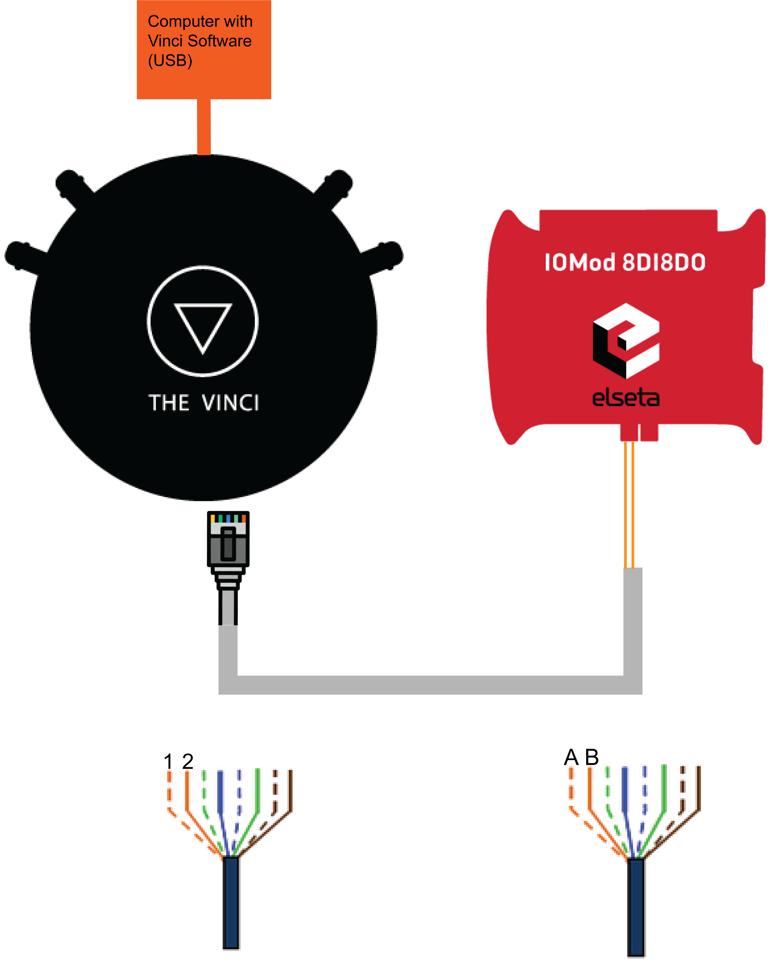
The first thing to do when setting up is to connect the IOMod to the computer using The Vinci Expert to convert from RS485 to USB. You need to connect it like in the diagram depicted below.
- Connect The Vinci Device to the computer using a micro USB cable.
- Using an ethernet cable connect one end to the Vinci, and the other two wires to IOMod A and B pins.
- If the wire is connected using RJ-45 the A wire will be the orange striped wire and the B wire will be the single color orange wire.
- Lastly, connect the 12-24 VDC power input.

To test IOmod with default settings, the user connects the device through RS485 to IEC 60870-5-103 master. For example, using “The Vinci Expert” as a serial interface converter and adapter to PC with “The Vinci” software. When opening “The Vinci” software, choose IEC 60870-5-103 – Master mode. Initial settings – 9600 baud rate; 8 data, no parity, 1 stop bit. Press Start, send Time synchronization, General interrogation, and go to the “Statistic” tab:
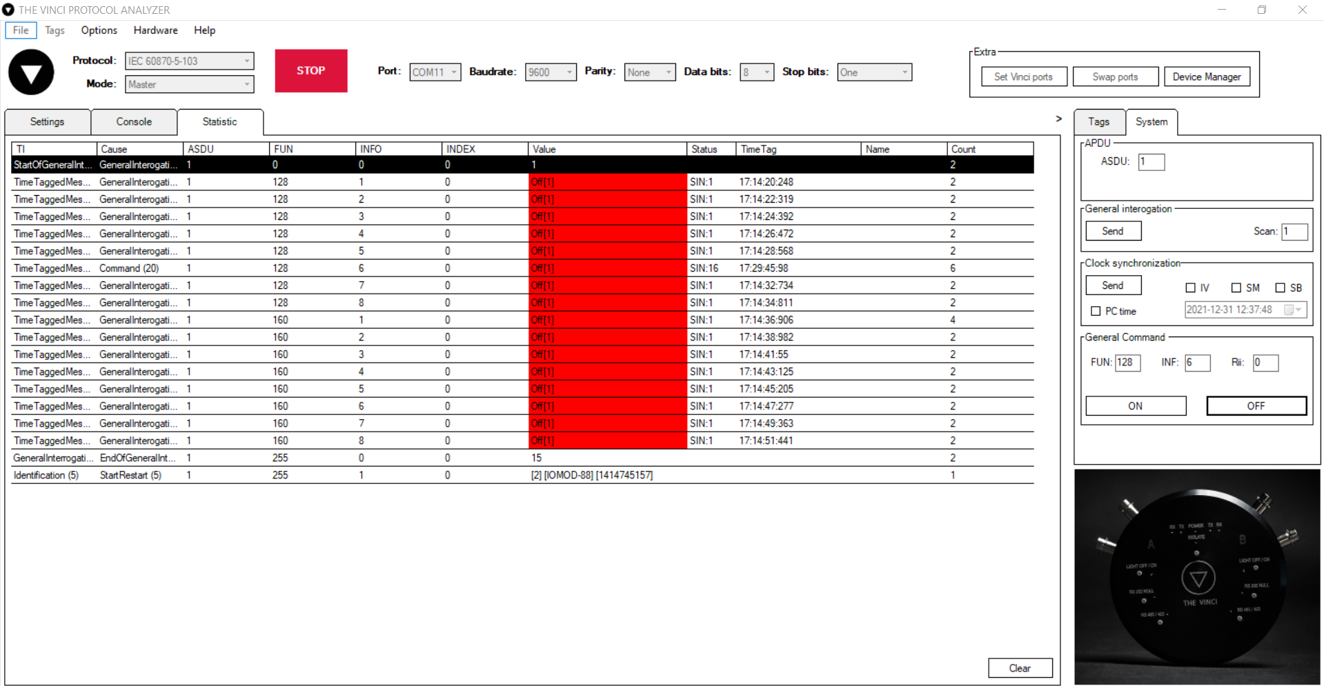
Fig. 1. Testing IOMOD device with “THE VINCI” software
As seen in Figure 1, Outputs and inputs are shown with info numbers 1-8, and function types are 128 and 160 respectively.
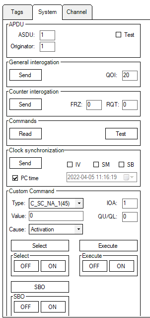
General Interrogation, Time Synchronization, and General Command options can be found on the right side of the program, in the “System” tab.
Output commands are controlled by the “General command” window on the right side of the program, in the “System” tab, with Output address (Function type) 128, and output number (Info number).
Figure 2 shows the 6th output command sent and the “CMD ACK” response received.
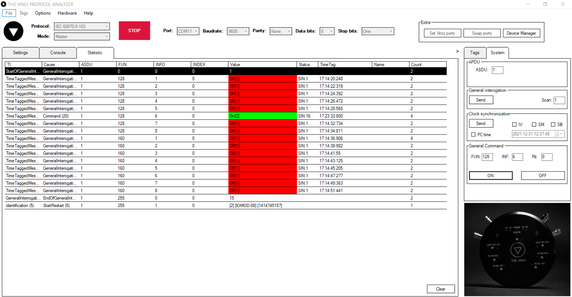
Fig. 2 Replies from IOmod device after a command has been sent through “THE VINCI” software
IEC 104 Slave Simulator for SCADA System
Initial Setup
All you need to do to set up is to be connected to a network from which the SCADA is reachable.
Standard settings in the Vinci software are for an RJ-45 cable, but it is configurable using the Hardware tab.
When you're connected to the network it's time to open The Vinci Software and start configuring the simulated device parameters. Since The Vinci Expert will simulate the Slave (Server) when the software is started just select the IEC 60870-5-104 protocol and select Slave mode.
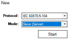 Fig. 1. Selecting Protocol and Mode.
Go to the settings tab once the software opens. Now it's time to configure your device according to your SCADA settings. The defaults that are here ar usually the defaults in most cases, but make sure to double-check. Also make sure to enter the IP and Port of the SCADA system they are located at the top of the window to the right of the green start button.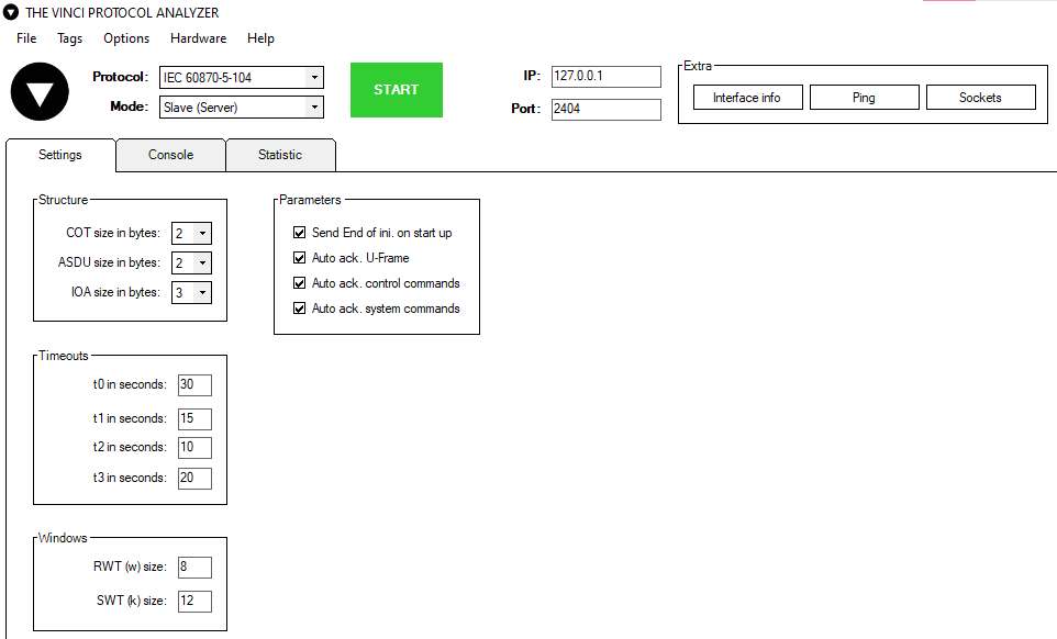
Fig. 2. Configuring settings according to SCADA
Data Configuration
To begin adding data to send just go to the tags tab on the right side and press the "Add" button.
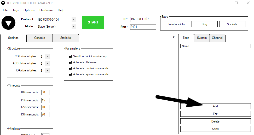
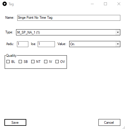
Now you can configure the data itself. Enter the tag name, select a desired type from the drop down list, type in the ASDU and IOA numbers and then select the value. The value field will change depending on the type selected.
Now you can press the Start button, and The Vinci Software should start establishing communication with the SCADA system. Just like it's depicted in figure 5. You can check the commands that are being sent and recieved in the Console tab.
If you want to add tags you can also do it even when the communication has been started.
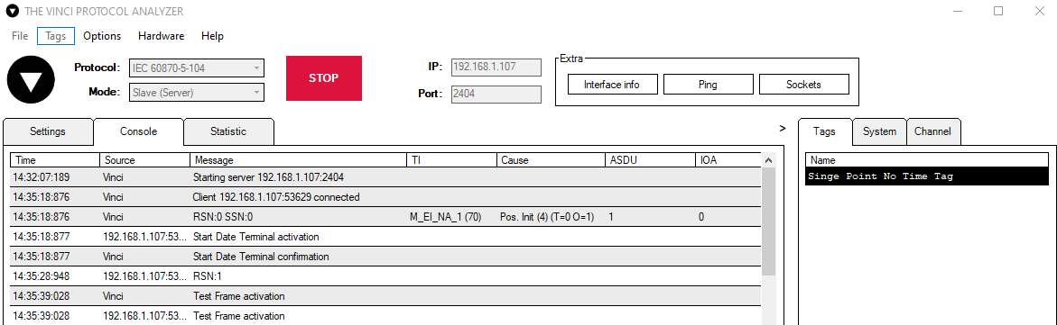
For simplicity purposes the SCADA used in this example was another instance of The Vinci Software. As you can see after General Interrogation has been sent the slave sends back the value of the tag that was just added. We can see what the value is if we check the statistics window in The Vinci Software. If the value were to be changed the slave would send the updated value automatically to the SCADA system.
All that's left to do is to add the other values you desire in the Tags window and the SCADA should be receiving them after it's done
If a new tag is added General Interrogation must be called for it to start sending data.
IEC-104 Master SCADA Setup
Initial Setup.
First connect to a network from which the IEC104 Slave device is reachable. When you're connected to the network it's time to open The Vinci Software and start configuring the SCADA parameters. The Vinci Expert will simulate the Master (Client) when the software is started select the IEC 60870-5-104 protocol and select Master mode, after making these selections press the start button.
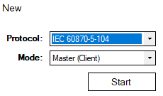
Fig. 1. Selecting Protocol and Mode.
Once the software opens go to the settings tab as depicted in the figure below. Then configure settings in accordance with the Slave device. The defaults that are here are usually good in most cases, but make sure to double-check. After configuring the parameters enter the IP and port of the SCADA system they are located at the top of the window to the right of the green start button.
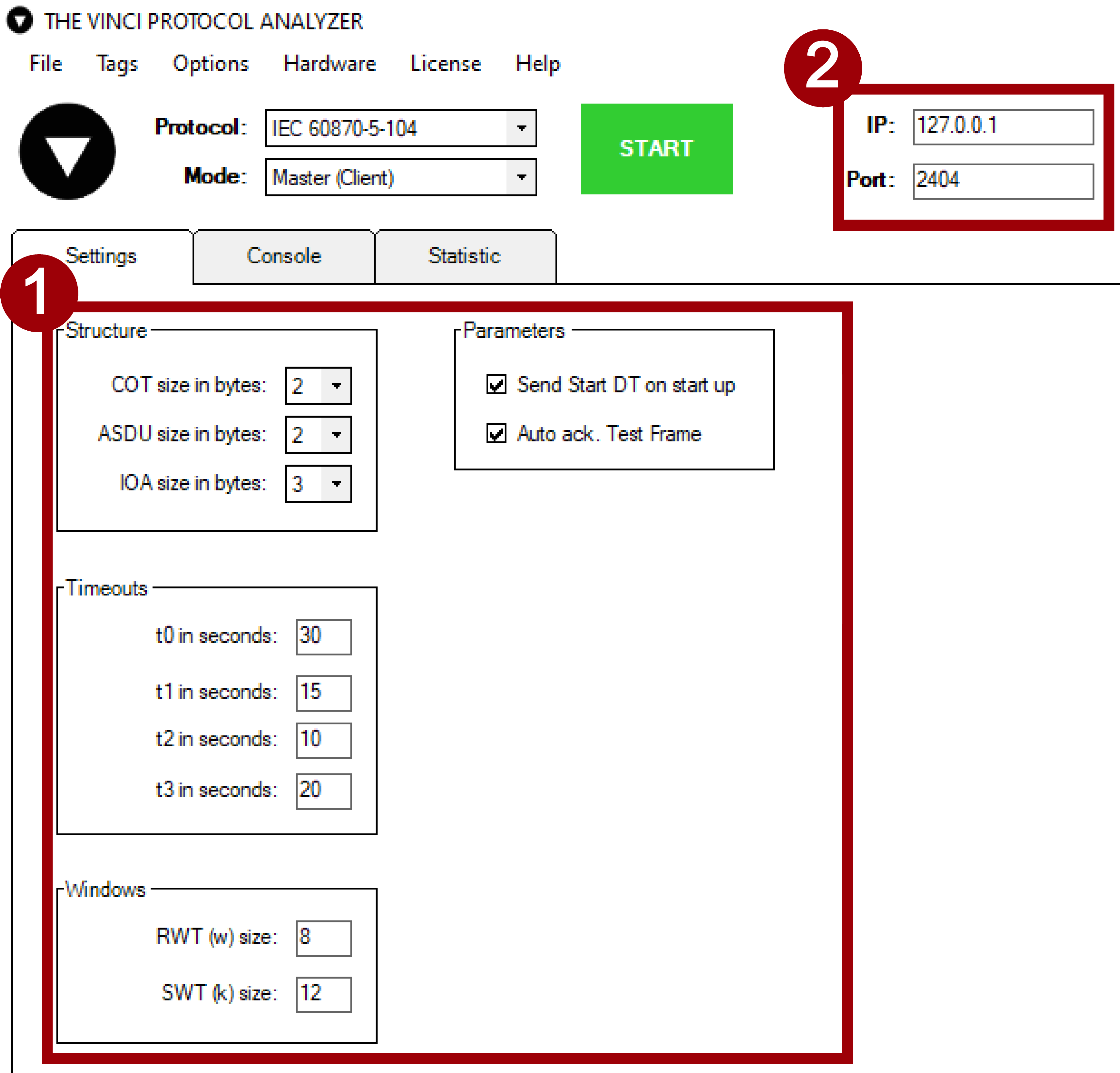
Fig. 2. Configuring settings according to SCADA
Establishing a connection.
To begin communication with IEC 104 Slave once everything is configured press the green Start button and communication should begin. If it doesn't check if you have entered the correct IP and the Slave is reachable by pinging.
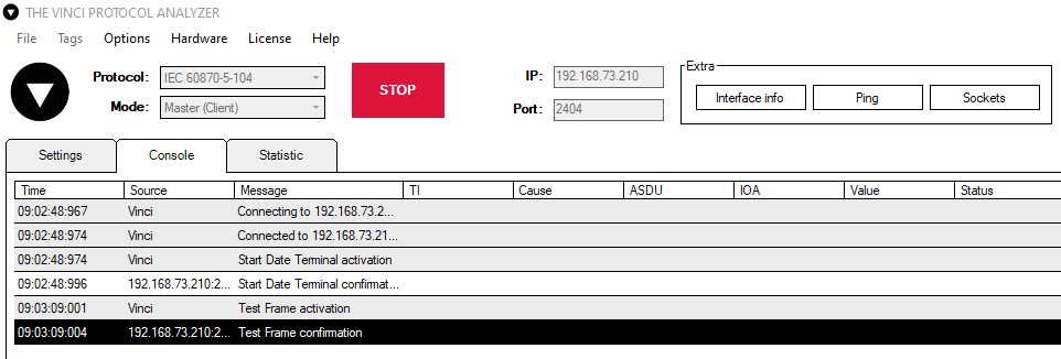
Fig. 3. Connection Established
Command overview.
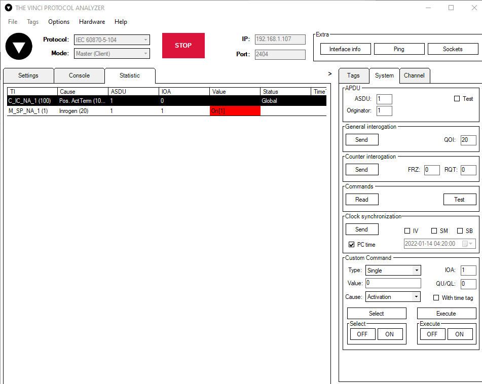
In the system tab, you can see all the IEC 104 commands that Vinci Software supports. A more detailed command description can be found here. To begin to send commands, first you need to configure your ASDU (CASDU) and Originator at the top of the System tab. (ASDU referred to here is the Common Adress or better known as CASDU). After entering the correct ASDU (CASDU) commands can now be sent. To check if the device is responding with the correct data, a good command to test is General interrogation.
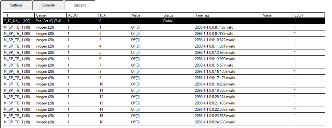
Slave response.
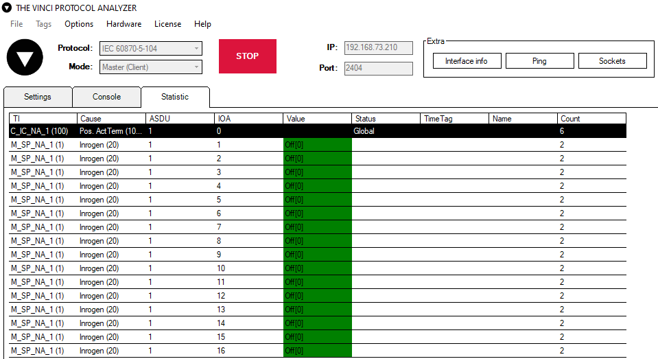
After sending the general interrogation command, the Slave device should respond with all the values that it is currently measuring. The Statistic tab will display all the gotten values in an orderly fashion, as depicted in the figure below. In this case, the data is gotten from a 16DI IOMod. As we can see, all the inputs are off.
Sending custom commands.
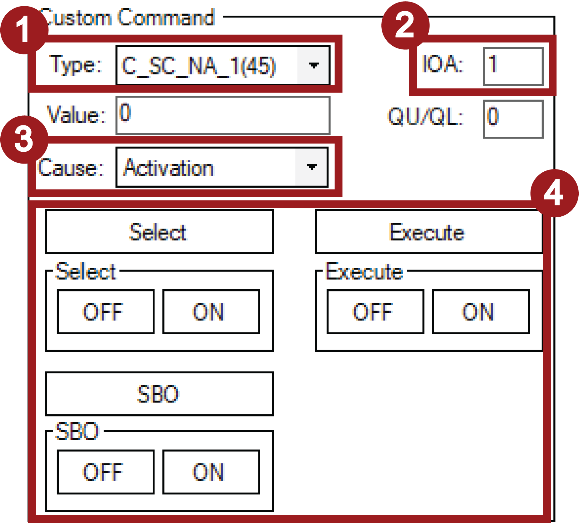
At the bottom of the system tab, you can configure it to send custom commands. To configure a custom command, follow these steps
- Select the type of the command.
- Enter the IOA (Information Object Address).
- Choose the command cause.
- Choose what type of command you want to send.
- If Select, Execute, or SBO (Select Before Operate) buttons are pressed, a command will be sent with the value entered in the value field.
- If ON or OFF buttons are pressed, values will automatically be filled. 0 meaning OFF and 1 meaning ON
w
Considering often used functionalities for SCADA, that is about it. Of course, all values in the statistics window can be formatted using tags, although it doesn't make much sense since all data from IEC104 Slave has a type defined in the packet, so Vinci Software automatically formats it for that type. And the channel tab is mainly for testing, because the Vinci software also automatically sends S-Frames and Start DT, Stop DT, and Test frame commands.
IEC 101 Master Simulator Tutorial
Initial Setup
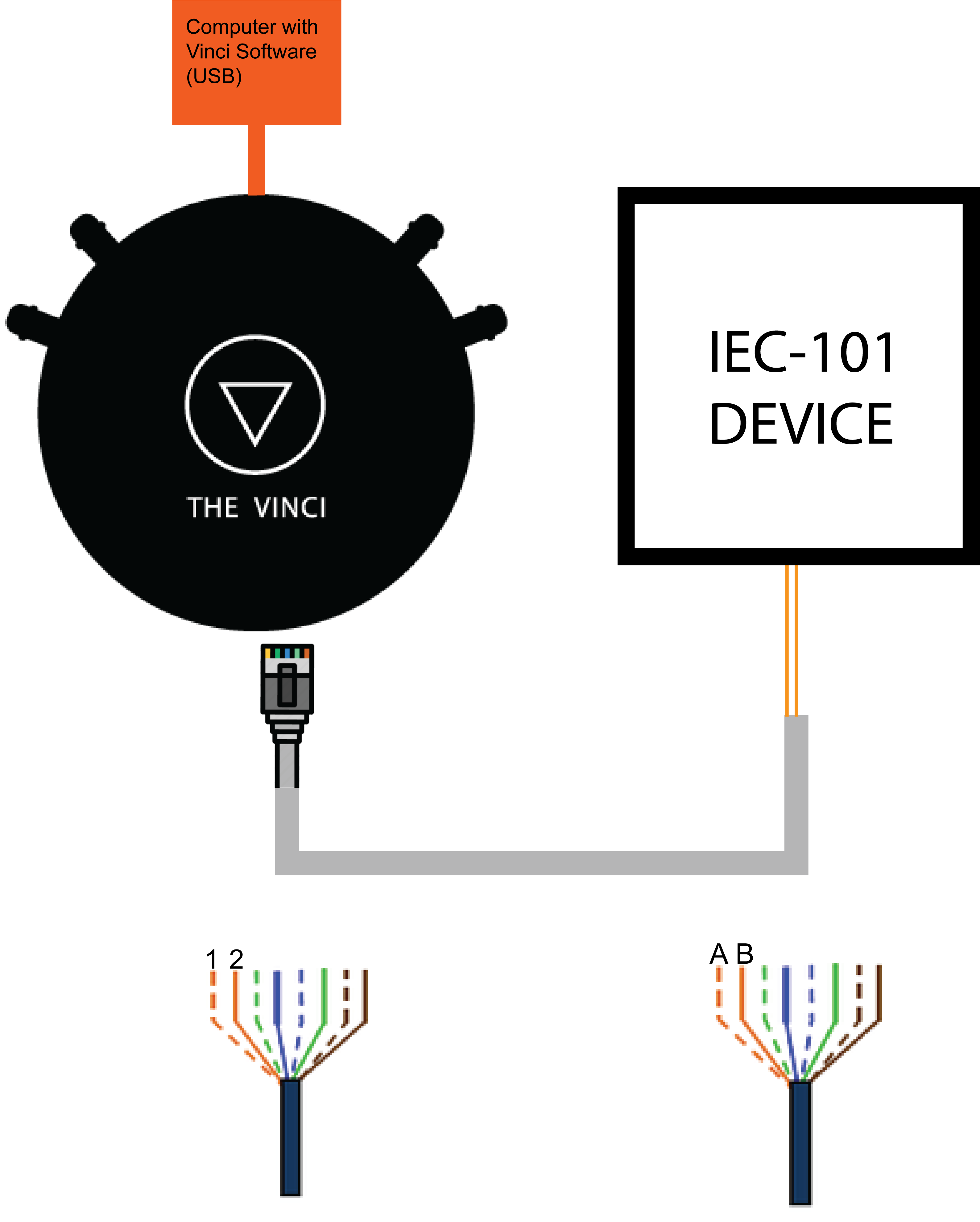
The first thing to do when setting up is to connect the IOMod to the computer using The Vinci Expert to convert from RS485 to USB. You need to connect it like in the diagram depicted below.
- Connect The Vinci Device to the computer using a micro USB cable.
- Using an ethernet cable connect one end to the Vinci, and the other two wires to IEC101 Device A and B pins.
- If the wire is connected using RJ-45 the A wire will be the orange striped wire and the B wire will be the single color orange wire.
Standard settings in the Vinci software are for an RJ-45 cable, but it is configurable using the Hardware tab.
Selecting protocol and mode
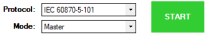 Fig. 1. Selecting protocol and mode
After the ethernet cable has been connected it's time to open The Vinci Software and start configuring the simulated device parameters. Since The Vinci Expert will simulate the Master (Client) when the software is started just select the IEC 60870-5-101 protocol and select Master mode.
Selecting the Serial parameters
 Fig. 2. Selecting the Serial parameters
The next step is to choose the correct serial port for your device and then set up serial communication parameters like baudrate, parity, databits, and stopbits in accordance with your device.
Selecting the protocol parameters
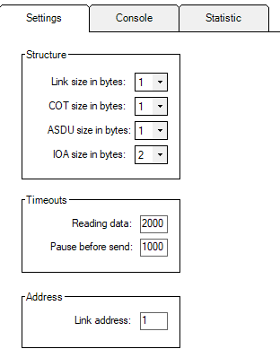 Fig. 3. Selecting the protocol parameters
Go to the settings tab when you have serial communication parameters configured. Now it's time to configure your device according to your Device settings. The defaults that are here are usually the defaults in most cases, but make sure to double-check.
Establishing a connection with the device
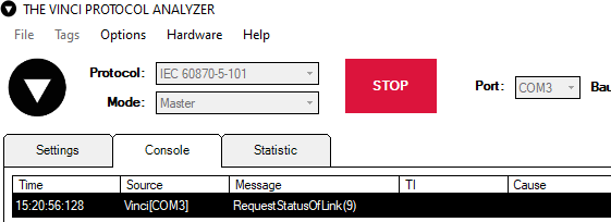 Fig. 4. Establishing a connection with the device.
Pressing the green "START" button should establish serial communication with the device. After the device responds with link status commands can be sent. Commands can be found on the right side of the Vinci software in the system tab.
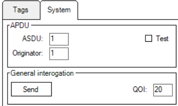
Calling General interrogation
 Fig. 5. Calling General interrogation
A simple command to start and check if the device is responding and/or configured correctly is General interrogation just press the send button and the command will be sent to the device.
Sending Clock synchronization
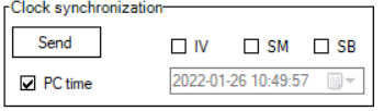 Fig. 6. Sending Clock synchronization
Another command that is usually sent whenever a connection is established is Clock synchronization. You can check the PC time checkbox so it sends the date of your computer and ignores whatever is selected in the date selection text box.
After sending the commands you desire all data that the slave responded with will be displayed in the statistics tab. In this case, the data is from a 16DI IOMod.
IEC 101 Slave Simulator Tutorial
Initial Setup
The first thing to do when setting up is to connect the IOMod to the computer using The Vinci Expert to convert from RS485 to USB. You need to connect it like in the diagram depicted below.
- Connect The Vinci Device to the computer using a micro USB cable.
- Using an ethernet cable or connect one end to the Vinci, and the other two wires to IEC101 Device A and B pins.
- If the wire is connected using RJ-45 the A wire will be the orange striped wire and the B wire will be the single color orange wire.
Standard settings in the Vinci software are for an RJ-45 cable, but it is configurable using the Hardware tab.
Selecting protocol and mode
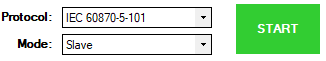
Fig. 1. Selecting protocol and mode
After the ethernet cable has been connected it's time to open The Vinci Software and start configuring the simulated device parameters. Since The Vinci Expert will simulate the Slave (Server) when the software is started just select the IEC 60870-5-101 protocol and select Slave mode.
Selecting the Serial parameters

Fig. 2. Selecting the Serial parameters
The next step is to choose the correct serial port for your device and then set up serial communication parameters like baudrate, parity, databits, and stopbits in accordance with your device.
Selecting the protocol parameters
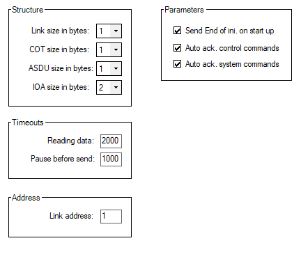
Fig. 3. Selecting the protocol parameters
Go to the settings tab when you have serial communication parameters configured. Now it's time to configure your device according to your Device settings. The defaults that are here are usually the defaults in most cases, but make sure to double-check.
Establishing a connection with the device
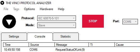
Fig. 4. Establishing a connection with the device.
Pressing the green "START" button should establish serial communication with the device. After the device responds with link status tags can be sent. Tags can be found on the right side of the Vinci software in the system tab.
Simulating an IOMod
This example will show how to simulate an IOMod using Vinci Protocol Analyzer. In the example below 4RTD IOMod is simulated.
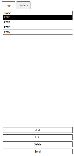
Firstly, to simulate an IOMod tags should be created by clicking "Add" button. Tags are simulating signals that would be overwise sent by a real IOMod (4RTD in this case).
In order to create a tag some values from Excel configuration will be required.
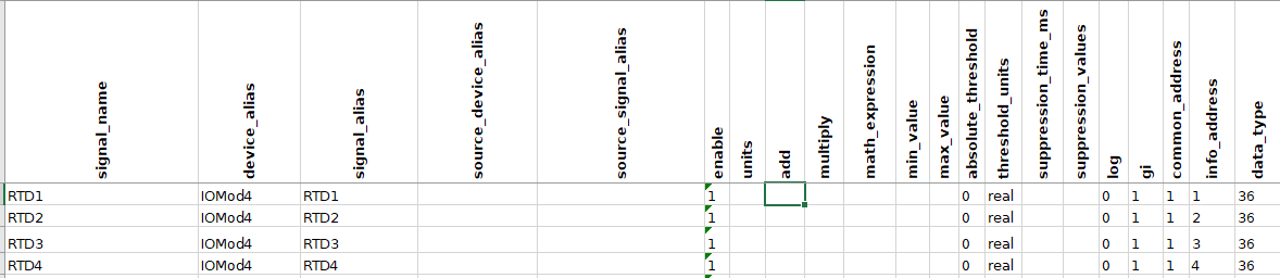 Fig. 6. Signals sheet of 4RTD IOMod.
In the picture below a tag creation window is shown. It opens after clicking "Add" button. To create a tag the Name has to be specified. After that the Type has to be specified. The type can be found in "data_type" column of Excel configuration. After that "Ioa" has to be specified. Its value for each tag can be found in "info_address" column. Lastly, a random value can be specified in "Value" box. Finally the tag can be saved by clicking "Save" button.

The created tags can be seen in WCC Lite Imported Signals section in browser.
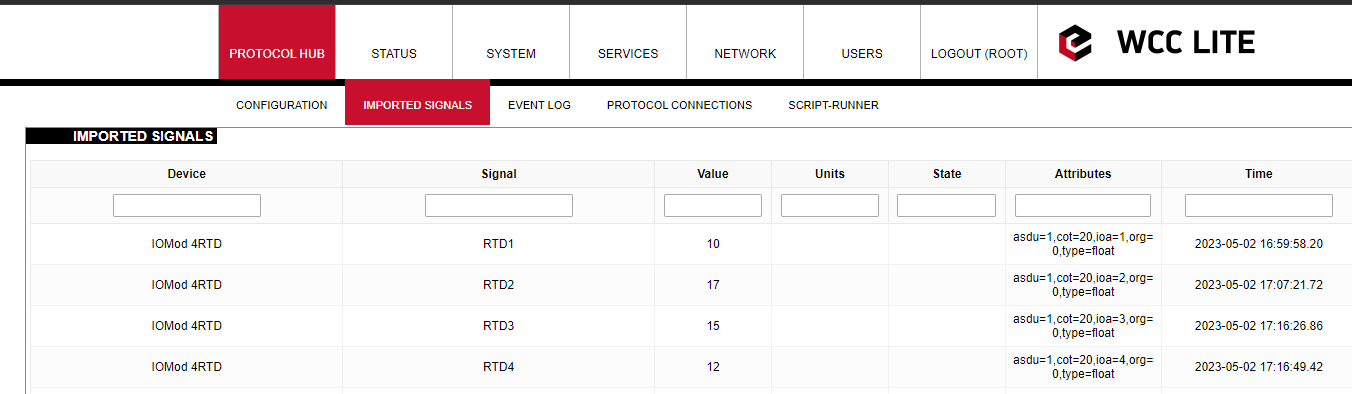 Fig. 8. Imported Signals tab in browser.
They can also be seen in Statistics section of Vinci application.
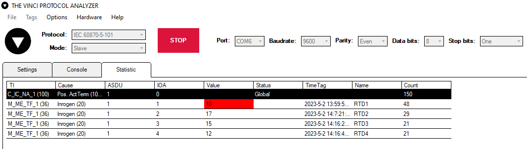
Fig. 9. Previously created tags in Statistics section of Vinci.
The state of the signals can be changed in System section of Vinci application by ticking Test or/and P/N options.
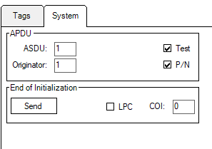
Fig. 10. Selecting Test and P/N options.
The change of signal states will be seen in WCC Lite Imported Signals section in browser.
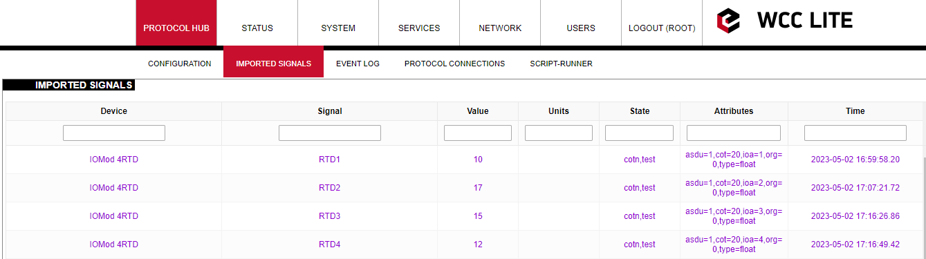
Fig. 11. Changed State of signals after selecting Test and P/N options.