| Pressing time | Description | Indication |
| Short Press | System reboot | Red STATUS LED starts blinking |
| Long press (>3s) | Reset to factory settings | Red STATUS LED turns on |
Note: Make sure that device is compatible with your power source before proceeding! Check the label next to power connector or on the side of device.
### SIM card slot (hardware versions older than 1.3) [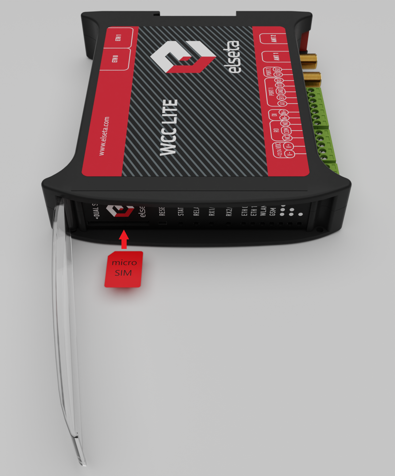](https://wiki.elseta.com/uploads/images/gallery/2022-11/image-1669195040713.png)As of hardware versions 1.3 onwards single SIM modem support for WCC Lite has been discontinued.
WCC Lite has push-push type microSIM card connector with card detection function. The connector is located on the front panel of WCC Lite. To access it, remove a transparent front panel cover. To insert a SIM card gently push it inside (see Figure below) until it locks in place. Press again to release and remove the card. [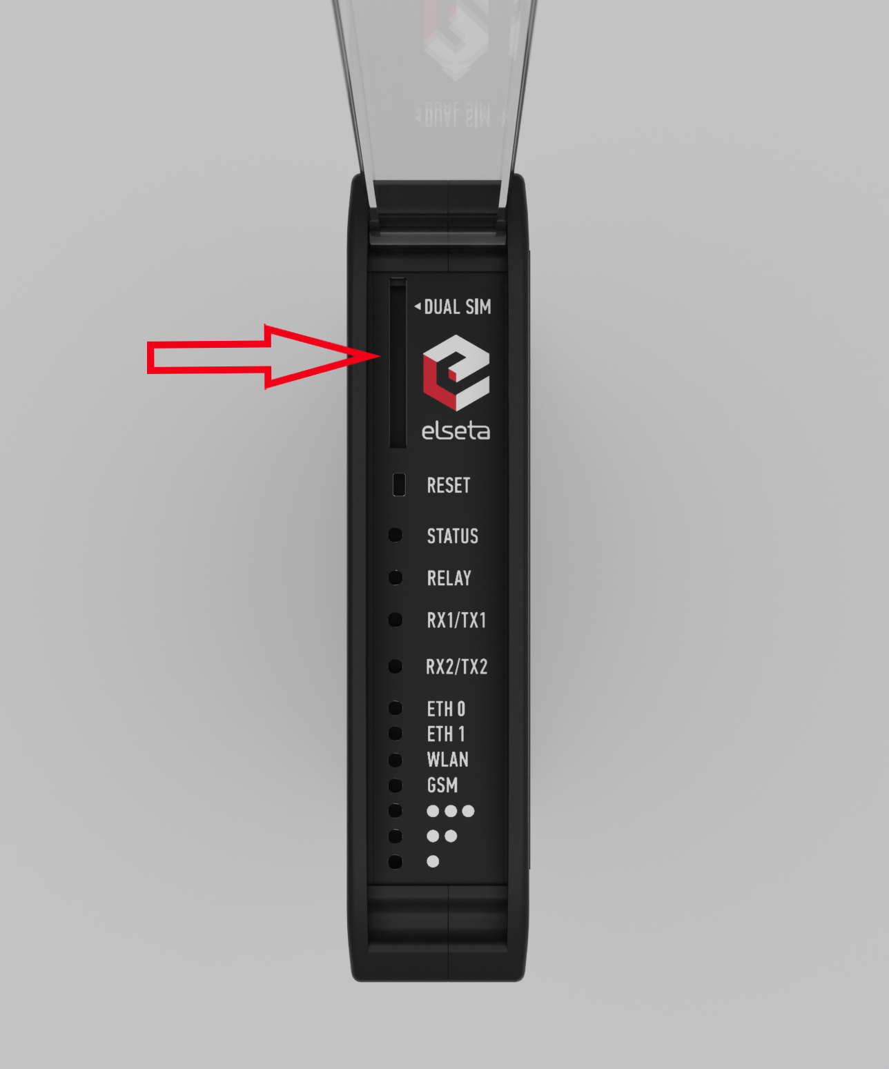](https://wiki.elseta.com/uploads/images/gallery/2022-11/image-1669195059373.png) ### Dual-SIM card slot WCC Lite has optional Dual-SIM card modem. To access both SIM cards, remove a transparent front panel cover and press through marked hole with small tool until SIM holder pops out. [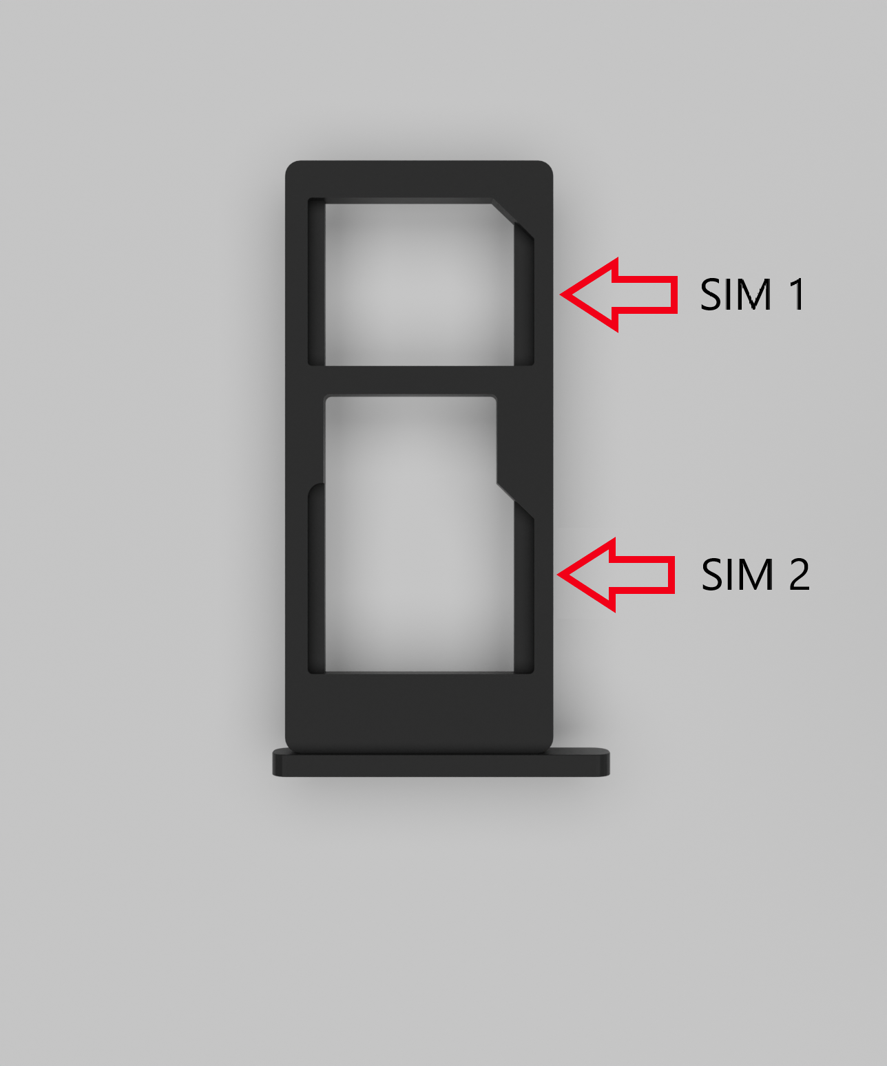](https://wiki.elseta.com/uploads/images/gallery/2022-11/image-1669195072668.png) To insert SIM cards, remove Dual-SIM holder and fit SIM cards into it. Insert holder with SIM cards into slot.Note: Be careful when removing or inserting DUAL-SIM holder, as SIM cards can fall out.
Note: WCC Lite will automatically detect a SIM card insertion or removing.
# WCC Lite interfaces WCC lite supports various interfaces to be acquire data and control external circuitry. That includes two serial port interfaces, relay output, digital input and external cellular connection antennae. ### Serial port interfaces WCC Lite WCC Lite has 2 serial ports (Figure 7). Selectable RS485 (by default) or RS232 interface on PORT1 and RS485 interface on PORT2. [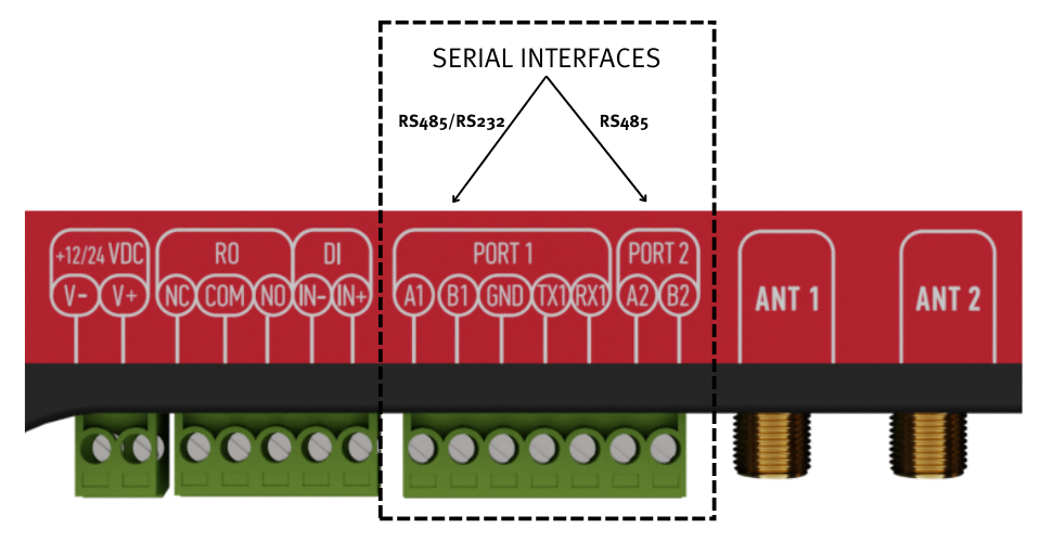](https://wiki.elseta.com/uploads/images/gallery/2022-11/image-1669195259955.png) WCC Lite RS485 interface supports baud rates up to 115200 and has an integrated 120 termination resistor. It is recommended to use termination at each end of the RS485 cable. To reduce reflections, keep the stubs (cable distance from main RS485 bus line) as short as possible when connecting device. See typical RS485 connection diagram on figure 8.Note: Double check if A and B wires are not mixed up.
WCC Lite 3-wire RS232 interface is available on PORT1 and can be selected by user (see Port settings). Baud rates up to 115200 are supported. See typical RS232 connection diagram on figure 9. [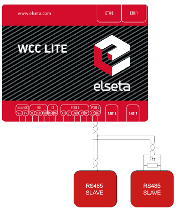](https://wiki.elseta.com/uploads/images/gallery/2020-10/image-1601990090504.png) [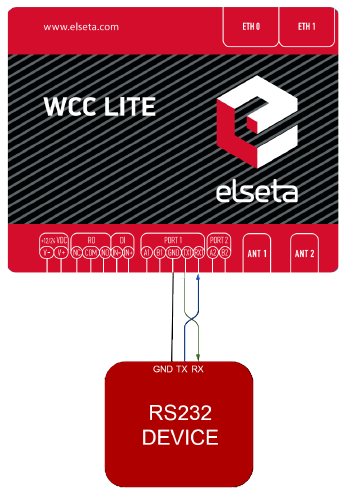 ](https://wiki.elseta.com/uploads/images/gallery/2020-10/image-1601990164490.png) ### Relay output WCC Lite integrates 1 signal relay (3-way RO connector) with COM (common), NC (normally closed) and NO (normally open) signals. [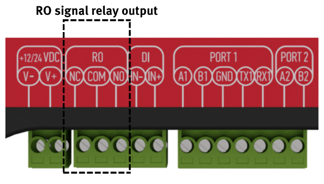](https://wiki.elseta.com/uploads/images/gallery/2022-11/image-1669195287416.png) Maximum switching power is 60W, maximum contact current is 2A, maximum switching voltage is 60VDC/60VAC. The lower is switching power, the higher is lifecycle of Relay Output. Relay electrical endurance: • resistive load, 30VDC / 1A - 30W min. 1x10⁵ operations; • resistive load, 30VDC / 2A - 60W min. 1x10⁴ operations. ### Digital Input With WCC Lite hardware version 1.4 a digital input functionality has been introduced. Software configuration guidelines are discussed later in this document. [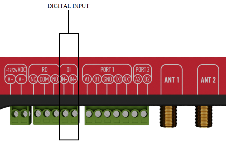](https://wiki.elseta.com/uploads/images/gallery/2022-11/image-1669195310853.png) ### GSM WCC Lite comes with an optional GSM module. There are few hardware configurations available: • Without GSM modem. • With single SIM modem (HW version 1.0 - 1.2) - 2G/3G (GPRS, EDGE / UMTS, HSDPA, HSUPA) version - 5.76Mb/s upload, 7.2Mb/s download. UMTS/HSPA bands 900, 2100. GSM bands 900, 1800. Modem chip - Ublox Sara-U270. • With single SIM modem (HW version 1.0 - 1.2) - 2G/4G (GPRS, EDGE / LTE) Cat 1 version - 10.3Mb/s upload, 5.2Mb/s download. LTE bands 3, 7, 20. GSM bands 900, 1800. Modem chip - Ublox Lara-R211. • With dual SIM modem (HW version 1.0 - 1.2) - 2G/3G (GPRS, EDGE / UMTS, HSDPA, HSUPA) version - 5.76Mb/s upload, 7.2Mb/s download. UMTS/HSPA bands 900, 2100. GSM bands 900, 1800. Modem chip - Ublox Sara-U270. • With dual SIM modem (HW version 1.0 - 1.2) - 2G/4G (GPRS, EDGE / LTE) Cat 1 version - 10.3Mb/s upload, 5.2Mb/s download. LTE bands 3, 7, 20. GSM bands 900, 1800. Modem chip - Ublox Lara-R211. • With dual SIM modem (HW version 1.3 - 1.4) - 2G/3G/4G (GPRS, EDGE / UMTS, HSDPA, HSUPA / LTE) Cat 4 version - 50Mb/s (max) upload, 150Mb/s (max) download. LTE bands 1, 3, 5, 7, 8, 20, 38, 40, 41. GSM bands 3, 8. UMTS bands 1, 5, 8. Modem chip - Quectel EC25-E. They are based on mini PCI-e standard connector and compatible with any other devices. Check label on package for current modification. [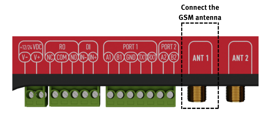](https://wiki.elseta.com/uploads/images/gallery/2022-11/image-1669195337401.png) Connect an antenna to the SMA connector labeled “ANT1“. Select a good antenna placement spot considering the operation environment and network coverage of your mobile provider in the area. To enable MIMO functionality for 4G (LTE) modems a second antenna should be connected to the SMA connector labeled ”ANT2”.4G (LTE) Cat 1 version modem both antennas are used for LTE communication. In such case internal WIFI antenna is used. Network can be limited in distance and speed, especially in metal based panels.
Make sure the signal level is over -80dBm to have a stable connection to the network. ### Wi-Fi For hardware version older than version 1.3, in case a Wi-Fi connection is needed, connect a Wi-fi antenna to the SMA connector labeled “WIFI“. Select a good antenna placement spot considering the operation environment. [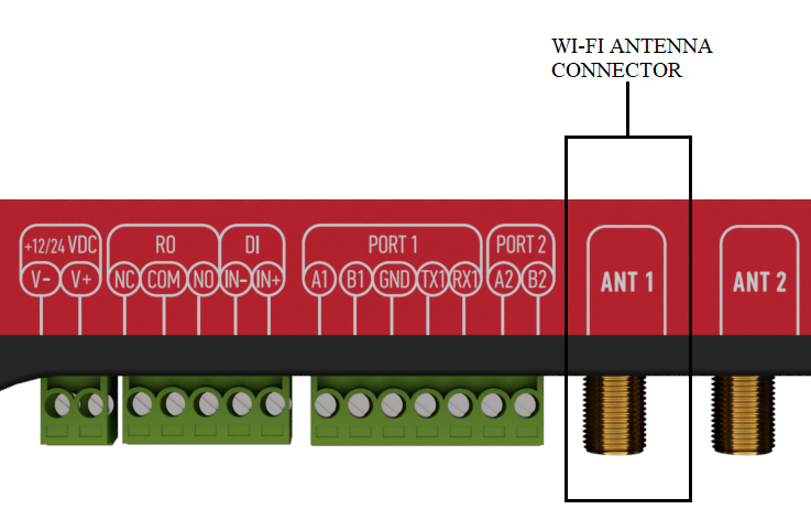](https://wiki.elseta.com/uploads/images/gallery/2022-11/image-1669195363170.png) Never hardware versions don’t have an option of connecting an external Wi-Fi antenna as MIMO capability for cellular modems has been introduced. In case stronger reach is needed, a user should contact manufacturer to provide possible solutions. Make sure the signal level is over -80dBm to have a stable connection to the network.