It is highly recommended that the RJ12 wire is not longer than 7 meters, otherwise the connection might be unstable.
To connect ConMod to a meter, an RJ12 cable is required. As shown in the picture below, one side of the cable is connected to a ConMod P1 port, and the other one to a meter. After connecting P1 LED will light up. Instructions on how to connect to a Wi-Fi are described below in the paragraph Connection and Configuration over Wi-Fi. [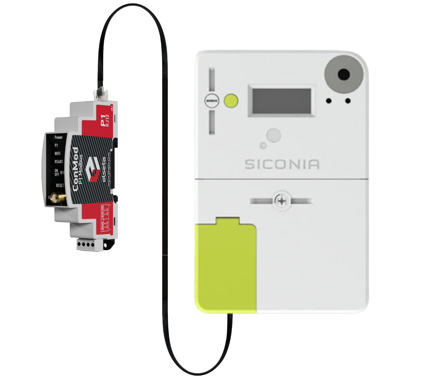](https://wiki.elseta.com/uploads/images/gallery/2024-04/image-1712673284471.png) Fig. 1. P1 connection to a smart meter via RJ12 cable [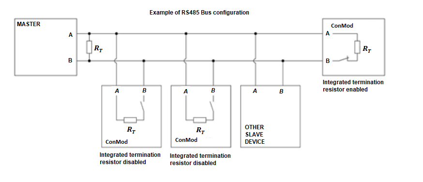](https://wiki.elseta.com/uploads/images/gallery/2024-04/image-1712673704198.png) Fig.2. RS485 Bus configuration ### Common configuration information ConMod receives data from meters via the P1 interface and sends data back via Modbus protocol using function 3 (read holding registers). Default serial communication parameters are:| slave id | 1 |
| Baud rate | 9600 |
| data bits | 8 |
| stop bits | 1 |
| parity | none |
| **Name** | **Units** | **Modbus register** | **Length** | **Number type** |
| serial number | - | 1 | 4 | UNSIGNED64 |
| correct data counter | - | 5 | 1 | UNSIGNED16 |
| faulty data counter | - | 6 | 1 | UNSIGNED16 |
| device error | - | 7 | 1 | UNSIGNED16 |
| Active energy import (+A) | Wh | 8 | 2 | UNSIGNED32 |
| Reactive energy import (+R) (QI+QII) | varh | 10 | 2 | UNSIGNED32 |
| Reactive energy export (-R) (QIII+QIV) | varh | 12 | 2 | UNSIGNED32 |
| Active energy import (+A) rate 1 | Wh | 14 | 2 | UNSIGNED32 |
| Active energy import (+A) rate 2 | - | 16 | 2 | UNSIGNED32 |
| Active energy import (+A) rate 3 | Wh | 18 | 2 | UNSIGNED32 |
| Active energy import (+A) rate 4 | Wh | 20 | 2 | UNSIGNED32 |
| Active energy export (−A) rate 1 | Wh | 22 | 2 | UNSIGNED32 |
| Active energy export (−A) rate 2 | Wh | 24 | 2 | UNSIGNED32 |
| Active energy export (−A) rate 3 | Wh | 26 | 2 | UNSIGNED32 |
| Active energy export (−A) rate 4 | Wh | 28 | 2 | UNSIGNED32 |
| Reactive energy (+R) rate 1 | varh | 30 | 2 | UNSIGNED32 |
| Reactive energy (+R) rate 2 | varh | 32 | 2 | UNSIGNED32 |
| Reactive energy (+R) rate 3 | varh | 34 | 2 | UNSIGNED32 |
| Reactive energy (+R) rate 4 | varh | 36 | 2 | UNSIGNED32 |
| Reactive energy (-R) rate 1 | varh | 38 | 2 | UNSIGNED32 |
| Reactive energy (-R) rate 2 | varh | 40 | 2 | UNSIGNED32 |
| Reactive energy (-R) rate 3 | varh | 42 | 2 | UNSIGNED32 |
| Reactive energy (-R) rate 4 | varh | 44 | 2 | UNSIGNED32 |
| Instantaneous voltage L1 | V | 46 | 2 | UNSIGNED32 |
| Average voltage L1 | V | 48 | 2 | UNSIGNED32 |
| Instantaneous current L1 | A | 50 | 2 | UNSIGNED32 |
| Sliding Average current L1 (for fuse supervision) | A | 52 | 2 | UNSIGNED32 |
| Instantaneous voltage L2 | V | 54 | 2 | UNSIGNED32 |
| Average voltage L2 | V | 56 | 2 | UNSIGNED32 |
| Instantaneous current L2 | A | 58 | 2 | UNSIGNED32 |
| Sliding Average current L2 (for fuse supervision) | A | 60 | 2 | UNSIGNED32 |
| Instantaneous voltage L3 | V | 62 | 2 | UNSIGNED32 |
| Average voltage L3 | V | 64 | 2 | UNSIGNED32 |
| Instantaneous current L3 | A | 66 | 2 | UNSIGNED32 |
| Sliding Average current L3 (for fuse supervision) | A | 68 | 2 | UNSIGNED32 |
| Instantaneous voltage (U) \[V\] | V | 70 | 2 | UNSIGNED32 |
| Instantaneous current \[A\] | A | 72 | 2 | UNSIGNED32 |
| Instantaneous current in neutral \[A\] | A | 74 | 2 | UNSIGNED32 |
| Instantaneous current (sum over all phases) | A | 76 | 2 | UNSIGNED32 |
| Instantaneous net frequency; any phase | Hz | 78 | 2 | UNSIGNED32 |
| Instantaneous active power (|+A|+|-A|) | W | 80 | 2 | UNSIGNED32 |
| Instantaneous active import power (+A) in phase L1 \[kW\] | W | 82 | 2 | UNSIGNED32 |
| Instantaneous active import power (+A) in phase L2 \[kW\] | W | 84 | 2 | UNSIGNED32 |
| Instantaneous active import power (+A) in phase L3 \[kW\] | W | 86 | 2 | UNSIGNED32 |
| Instantaneous active export power (-A) in phase L1 \[kW\] | W | 88 | 2 | UNSIGNED32 |
| Instantaneous active export power (-A) in phase L2 \[kW\] | W | 90 | 2 | UNSIGNED32 |
| Instantaneous active export power (-A) in phase L3 \[kW\] | W | 92 | 2 | UNSIGNED32 |
| Instantaneous reactive import power (+R) in phase L1 \[kvar\] | var | 94 | 2 | UNSIGNED32 |
| Instantaneous reactive import power (+R) in phase L2 \[kvar\] | var | 96 | 2 | UNSIGNED32 |
| Instantaneous reactive import power (+R) in phase L3 \[kvar\] | var | 98 | 2 | UNSIGNED32 |
| Instantaneous reactive export power (-R) in phase L1 \[kvar\] | var | 100 | 2 | UNSIGNED32 |
| Instantaneous reactive export power (-R) in phase L2 \[kvar\] | var | 102 | 2 | UNSIGNED32 |
| Instantaneous reactive export power (-R) in phase L3 \[kvar\] | var | 104 | 2 | UNSIGNED32 |
| Instantaneous apparent import power (+VA) | VA | 106 | 2 | UNSIGNED32 |
| Instantaneous apparent import power (+VA) in phase L1 | VA | 108 | 2 | UNSIGNED32 |
| Instantaneous apparent import power (+VA) in phase L2 | VA | 110 | 2 | UNSIGNED32 |
| Instantaneous apparent import power (+VA) in phase L3 | VA | 112 | 2 | UNSIGNED32 |
| Instantaneous apparent export power (-VA) | VA | 114 | 2 | UNSIGNED32 |
| Instantaneous apparent export power (-VA) in phase L1 | VA | 116 | 2 | UNSIGNED32 |
| Instantaneous apparent export power (-VA) in phase L2 | VA | 118 | 2 | UNSIGNED32 |
| Instantaneous apparent export power (-VA) in phase L3 | VA | 120 | 2 | UNSIGNED32 |
| Average Import Power (+A) | W | 122 | 2 | UNSIGNED32 |
| Average Net Power (|+A|-|-A|) | W | 124 | 2 | SIGNED32 |
| Average Total Power (|+A|+|-A|) | W | 126 | 2 | UNSIGNED32 |
| Instantaneous Power factor (+A/+VA) | - | 128 | 2 | SIGNED32 |
| Instantaneous power factor in phase L1 | - | 130 | 2 | SIGNED32 |
| Instantaneous power factor in phase L2 | - | 132 | 2 | SIGNED32 |
| Instantaneous power factor in phase L3 | - | 134 | 2 | SIGNED32 |
| Minimum Power factor (+A/+VA) | - | 136 | 2 | SIGNED32 |
| Measurement Period 3 for Instantaneous values | s | 138 | 2 | UNSIGNED32 |
| Demand Register 1 - Active energy import (+A) | W | 140 | 2 | UNSIGNED32 |
| Demand Register 2 - Active energy export (−A) | W | 142 | 2 | UNSIGNED32 |
| Demand Register 3 - Reactive energy import (+R) | var | 144 | 2 | UNSIGNED32 |
| Demand Register 4 - Reactive energy export (-R) | var | 146 | 2 | UNSIGNED32 |
| Demand Register 5 - Apparent energy import (+VA) | VA | 148 | 2 | UNSIGNED32 |
| Demand Register 6 - Apparent energy export (-VA) | VA | 150 | 2 | UNSIGNED32 |
| Last Average Demand Register 1 - Active energy import (+A) | W | 152 | 2 | UNSIGNED32 |
| Last Average Demand Register 2 - Active energy export (−A) | W | 154 | 2 | UNSIGNED32 |
| Last Average Demand Register 3 - Reactive energy import (+R) | var | 156 | 2 | UNSIGNED32 |
| Last Average Demand Register 4 - Reactive energy export (-R) | var | 158 | 2 | UNSIGNED32 |
| Last Average Demand Register 5 - Apparent energy import (+VA) | VA | 160 | 2 | UNSIGNED32 |
| Last Average Demand Register 6 - Apparent energy export (-VA) | VA | 162 | 2 | UNSIGNED32 |
| Duration of last voltage sag in phase L1 | s | 164 | 2 | UNSIGNED32 |
| Duration of last voltage sag in phase L2 | s | 166 | 2 | UNSIGNED32 |
| Duration of last voltage sag in phase L3 | s | 168 | 2 | UNSIGNED32 |
| Magnitude of last voltage sag in phase L1 | V | 170 | 2 | UNSIGNED32 |
| Magnitude of last voltage sag in phase L2 | V | 172 | 2 | UNSIGNED32 |
| Magnitude of last voltage sag in phase L3 | V | 174 | 2 | UNSIGNED32 |
| Duration of last voltage swell in phase L1 | s | 176 | 2 | UNSIGNED32 |
| Duration of last voltage swell in phase L2 | s | 178 | 2 | UNSIGNED32 |
| Duration of last voltage swell in phase L3 | s | 180 | 2 | UNSIGNED32 |
| Magnitude of last voltage swell in phase L1 | V | 182 | 2 | UNSIGNED32 |
| Magnitude of last voltage swell in phase L2 | V | 184 | 2 | UNSIGNED32 |
| Magnitude of last voltage swell in phase L3 | V | 186 | 2 | UNSIGNED32 |
| **Name** | **Description** | **Range** |
| SIGNED16 | 16-bit signed integer (1 word) | -32768...+32767 |
| UNSIGNED16 | 16-bit unsigned integer (1 word) | 0...65535 |
| SIGNED32 | 32-bit signed integer (2 words) | -2 147 483 648... + 2 147 483 647 |
| UNSIGNED32 | 32-bit unsigned integer (2 word) | 0... 4 294 967 295 |
| **System** | ||
| 1. | Dimension | 91 x 18 x 67 mm |
| 2. | Working temperature | -25°C | +55°C |
| 3. | Recommended operating conditions | -25°C | +55°C and >95 %RH (none condensing) |
| 4. | Configuration | Web browser (Laptop and smartphone) |
| **Electrical specifications** | ||
| 5. | Functions | - P1 interface - Connectivity – 0,5m 6pin cable with RJ12 connectors - Overvoltage protection up to ±65V |
| **Power** | ||
| 6. | Power Supply | 5V to 60V |
| 7. | Current consumption | <200mA @12 VDC |
It is highly recommended that the RJ12 wire is not longer than 7 meters, otherwise the connection might be unstable.
To connect ConMod to a meter, an RJ12 cable is required. As shown in the picture below, one side of the cable is connected to a ConMod P1 port, and the other one to a meter. After connecting P1 LED will light up. Instructions on how to connect to a Wi-Fi are described below in the paragraph Connection and Configuration over Wi-Fi. [](https://wiki.elseta.com/uploads/images/gallery/2024-04/image-1712673284471.png) Fig. 1. P1 connection to a smart meter via RJ12 cable [](https://wiki.elseta.com/uploads/images/gallery/2024-04/image-1712673704198.png) Fig.2. RS485 Bus configuration ### Common configuration information ConMod receives data from meters via the P1 interface and sends data back via Modbus protocol using function 3 (read holding registers). Default serial communication parameters are:| slave id | 1 |
| Baud rate | 9600 |
| data bits | 8 |
| stop bits | 1 |
| parity | none |
| **Name** | **Units** | **Modbus register** | **Obis job** | **Length** | **Number type** |
| serial number | - | 1 | - | 4 | UNSIGNED64 |
| correct data counter | - | 5 | - | 1 | UNSIGNED16 |
| faulty data counter | - | 6 | - | 1 | UNSIGNED16 |
| device error | - | 7 | - | 1 | UNSIGNED16 |
| Active energy import (+A) | Wh | 8 | 1-0:1.8.0 | 2 | UNSIGNED32 |
| Active energy export (-A) | Wh | 10 | 1-0:2.8.0 | 2 | UNSIGNED32 |
| Reactive energy import (+R) (QI+QII) | varh | 12 | 1-0:3.8.0 | 2 | UNSIGNED32 |
| Reactive energy export (-R) (QIII+QIV) | varh | 14 | 1-0:4.8.0 | 2 | UNSIGNED32 |
| Active energy import (+A) rate 1 | Wh | 16 | 1-0:1.8.1 | 2 | UNSIGNED32 |
| Active energy import (+A) rate 2 | Wh | 18 | 1-0:1.8.2 | 2 | UNSIGNED32 |
| Active energy import (+A) rate 3 | Wh | 20 | 1-0:1.8.3 | 2 | UNSIGNED32 |
| Active energy import (+A) rate 4 | Wh | 22 | 1-0:1.8.4 | 2 | UNSIGNED32 |
| Active energy export (−A) rate 1 | Wh | 24 | 1-0:2.8.1 | 2 | UNSIGNED32 |
| Active energy export (−A) rate 2 | Wh | 26 | 1-0:2.8.2 | 2 | UNSIGNED32 |
| Active energy export (−A) rate 3 | Wh | 28 | 1-0:2.8.3 | 2 | UNSIGNED32 |
| Active energy export (−A) rate 4 | Wh | 30 | 1-0:2.8.4 | 2 | UNSIGNED32 |
| Reactive energy (+R) rate 1 | varh | 32 | 1-0:3.8.1 | 2 | UNSIGNED32 |
| Reactive energy (+R) rate 2 | varh | 34 | 1-0:3.8.2 | 2 | UNSIGNED32 |
| Reactive energy (+R) rate 3 | varh | 36 | 1-0:3.8.3 | 2 | UNSIGNED32 |
| Reactive energy (+R) rate 4 | varh | 38 | 1-0:3.8.4 | 2 | UNSIGNED32 |
| Reactive energy (-R) rate 1 | varh | 40 | 1-0:4.8.1 | 2 | UNSIGNED32 |
| Reactive energy (-R) rate 2 | varh | 42 | 1-0:4.8.2 | 2 | UNSIGNED32 |
| Reactive energy (-R) rate 3 | varh | 44 | 1-0:4.8.3 | 2 | UNSIGNED32 |
| Reactive energy (-R) rate 4 | varh | 46 | 1-0:4.8.4 | 2 | UNSIGNED32 |
| Instantaneous active import power (+A) | Wh | 48 | 1-0:1.7.0 | 2 | UNSIGNED32 |
| Instantaneous active export power (-A) | Wh | 50 | 1-0:2.7.0 | 2 | UNSIGNED32 |
| Instantaneous reactive import power (+R) | varh | 52 | 1-0:3.7.0 | 2 | UNSIGNED32 |
| Instantaneous reactive export power (-R) | varh | 54 | 1-0:4.7.0 | 2 | UNSIGNED32 |
| Instantaneous voltage L1 | V | 56 | 1-0:32.7.0 | 2 | UNSIGNED32 |
| Average voltage L1 | V | 58 | 1-0:32.24.0 | 2 | UNSIGNED32 |
| Instantaneous current L1 | A | 60 | 1-0:31.7.0 | 2 | UNSIGNED32 |
| Sliding Average current L1 (for fuse supervision) | A | 62 | 1-0:31.4.0 | 2 | UNSIGNED32 |
| Instantaneous voltage L2 | V | 64 | 1-0:52.7.0 | 2 | UNSIGNED32 |
| Average voltage L2 | V | 66 | 1-0:52.24.0 | 2 | UNSIGNED32 |
| Instantaneous current L2 | A | 68 | 1-0:51.7.0 | 2 | UNSIGNED32 |
| Sliding Average current L2 (for fuse supervision) | A | 70 | 1-0:51.4.0 | 2 | UNSIGNED32 |
| Instantaneous voltage L3 | V | 72 | 1-0:72.7.0 | 2 | UNSIGNED32 |
| Average voltage L3 | V | 74 | 1-0:72.24.0 | 2 | UNSIGNED32 |
| Instantaneous current L3 | A | 76 | 1-0:71.7.0 | 2 | UNSIGNED32 |
| Sliding Average current L3 (for fuse supervision) | A | 78 | 1-0:71.4.0 | 2 | UNSIGNED32 |
| Instantaneous voltage (U) \[V\] | V | 80 | 1-0:12.7.0 | 2 | UNSIGNED32 |
| Instantaneous current \[A\] | A | 82 | 1-0:11.7.0 | 2 | UNSIGNED32 |
| Instantaneous current in neutral \[A\] | A | 84 | 1-0:91.7.0 | 2 | UNSIGNED32 |
| Instantaneous current (sum over all phases) | A | 86 | 1-0:90.7.0 | 2 | UNSIGNED32 |
| Instantaneous net frequency; any phase | Hz | 88 | 1-0:14.7.0 | 2 | UNSIGNED32 |
| Instantaneous active power (|+A|+|-A|) | W | 90 | 1-0:15.7.0 | 2 | UNSIGNED32 |
| Instantaneous active import power (+A) in phase L1 \[kW\] | W | 92 | 1-0:21.7.0 | 2 | UNSIGNED32 |
| Instantaneous active import power (+A) in phase L2 \[kW\] | W | 94 | 1-0:41.7.0 | 2 | UNSIGNED32 |
| Instantaneous active import power (+A) in phase L3 \[kW\] | W | 96 | 1-0:61.7.0 | 2 | UNSIGNED32 |
| Instantaneous active export power (-A) in phase L1 \[kW\] | W | 98 | 1-0:22.7.0 | 2 | UNSIGNED32 |
| Instantaneous active export power (-A) in phase L2 \[kW\] | W | 100 | 1-0:42.7.0 | 2 | UNSIGNED32 |
| Instantaneous active export power (-A) in phase L3 \[kW\] | W | 102 | 1-0:62.7.0 | 2 | UNSIGNED32 |
| Instantaneous reactive import power (+R) in phase L1 \[kvar\] | var | 104 | 1-0:23.7.0 | 2 | UNSIGNED32 |
| Instantaneous reactive import power (+R) in phase L2 \[kvar\] | var | 106 | 1-0:43.7.0 | 2 | UNSIGNED32 |
| Instantaneous reactive import power (+R) in phase L3 \[kvar\] | var | 108 | 1-0:63.7.0 | 2 | UNSIGNED32 |
| Instantaneous reactive export power (-R) in phase L1 \[kvar\] | var | 110 | 1-0:24.7.0 | 2 | UNSIGNED32 |
| Instantaneous reactive export power (-R) in phase L2 \[kvar\] | var | 112 | 1-0:44.7.0 | 2 | UNSIGNED32 |
| Instantaneous reactive export power (-R) in phase L3 \[kvar\] | var | 114 | 1-0:64.7.0 | 2 | UNSIGNED32 |
| Instantaneous apparent import power (+VA) | VA | 116 | 1-0:9.7.0 | 2 | UNSIGNED32 |
| Instantaneous apparent import power (+VA) in phase L1 | VA | 118 | 1-0:29.7.0 | 2 | UNSIGNED32 |
| Instantaneous apparent import power (+VA) in phase L2 | VA | 120 | 1-0:49.7.0 | 2 | UNSIGNED32 |
| Instantaneous apparent import power (+VA) in phase L3 | VA | 122 | 1-0:69.7.0 | 2 | UNSIGNED32 |
| Instantaneous apparent export power (-VA) | VA | 124 | 1-0:10.7.0 | 2 | UNSIGNED32 |
| Instantaneous apparent export power (-VA) in phase L1 | VA | 126 | 1-0:30.7.0 | 2 | UNSIGNED32 |
| Instantaneous apparent export power (-VA) in phase L2 | VA | 128 | 1-0:50.7.0 | 2 | UNSIGNED32 |
| Instantaneous apparent export power (-VA) in phase L3 | VA | 130 | 1-0:70.7.0 | 2 | UNSIGNED32 |
| Average Import Power (+A) | W | 132 | 1-0:1.24.0 | 2 | UNSIGNED32 |
| Average Net Power (|+A|-|-A|) | W | 134 | 1-0:16.24.0 | 2 | SIGNED32 |
| Average Total Power (|+A|+|-A|) | W | 136 | 1-0:15.24.0 | 2 | UNSIGNED32 |
| Instantaneous Power factor (+A/+VA) | - | 138 | 1-0:13.7.0 | 2 | UNSIGNED32 |
| Instantaneous power factor in phase L1 | - | 140 | 1-0:33.7.0 | 2 | UNSIGNED32 |
| Instantaneous power factor in phase L2 | - | 142 | 1-0:53.7.0 | 2 | UNSIGNED32 |
| Instantaneous power factor in phase L3 | - | 144 | 1-0:73.7.0 | 2 | UNSIGNED32 |
| Minimum Power factor (+A/+VA) | - | 146 | 1-0:13.3.0 | 2 | UNSIGNED32 |
| Measurement Period 3 for Instantaneous values | s | 148 | 1-0:0.8.2 | 2 | UNSIGNED32 |
| Demand Register 1 - Active energy import (+A) | W | 150 | 1-0:1.4.0 | 2 | UNSIGNED32 |
| Demand Register 2 - Active energy export (−A) | W | 152 | 1-0:2.4.0 | 2 | UNSIGNED32 |
| Demand Register 3 - Reactive energy import (+R) | var | 154 | 1-0:3.4.0 | 2 | UNSIGNED32 |
| Demand Register 4 - Reactive energy export (-R) | var | 156 | 1-0:4.4.0 | 2 | UNSIGNED32 |
| Demand Register 5 - Apparent energy import (+VA) | VA | 158 | 1-0:9.4.0 | 2 | UNSIGNED32 |
| Demand Register 6 - Apparent energy export (-VA) | VA | 160 | 1-0:10.4.0 | 2 | UNSIGNED32 |
| Last Average Demand Register 1 - Active energy import (+A) | W | 162 | 1-0:1.5.0 | 2 | UNSIGNED32 |
| Last Average Demand Register 2 - Active energy export (−A) | W | 164 | 1-0:2.5.0 | 2 | UNSIGNED32 |
| Last Average Demand Register 3 - Reactive energy import (+R) | var | 166 | 1-0:3.5.0 | 2 | UNSIGNED32 |
| Last Average Demand Register 4 - Reactive energy export (-R) | var | 168 | 1-0:4.5.0 | 2 | UNSIGNED32 |
| Last Average Demand Register 5 - Apparent energy import (+VA) | VA | 170 | 1-0:9.5.0 | 2 | UNSIGNED32 |
| Last Average Demand Register 6 - Apparent energy export (-VA) | VA | 172 | 1-0:10.5.0 | 2 | UNSIGNED32 |
| Number of voltage sags in phase L1 | - | 174 | 1-0:32.32.0 | 2 | UNSIGNED32 |
| Number of voltage sags in phase L2 | - | 176 | 1-0:52.32.0 | 2 | UNSIGNED32 |
| Number of voltage sags in phase L3 | - | 178 | 1-0:72.32.0 | 2 | UNSIGNED32 |
| Duration of last voltage sag in phase L1 | s | 180 | 1-0:32.33.0 | 2 | UNSIGNED32 |
| Duration of last voltage sag in phase L2 | s | 182 | 1-0:52.33.0 | 2 | UNSIGNED32 |
| Duration of last voltage sag in phase L3 | s | 184 | 1-0:72.33.0 | 2 | UNSIGNED32 |
| Magnitude of last voltage sag in phase L1 | V | 186 | 1-0:32.34.0 | 2 | UNSIGNED32 |
| Magnitude of last voltage sag in phase L2 | V | 188 | 1-0:52.34.0 | 2 | UNSIGNED32 |
| Magnitude of last voltage sag in phase L3 | V | 190 | 1-0:72.34.0 | 2 | UNSIGNED32 |
| Number of voltage swells in phase L1 | - | 192 | 1-0:32.36.0 | 2 | UNSIGNED32 |
| Number of voltage swells in phase L2 | - | 194 | 1-0:52.36.0 | 2 | UNSIGNED32 |
| Number of voltage swells in phase L3 | - | 196 | 1-0:72.36.0 | 2 | UNISGNED32 |
| Duration of last voltage swell in phase L1 | s | 198 | 1-0:32.37.0 | 2 | UNSIGNED32 |
| Duration of last voltage swell in phase L2 | s | 200 | 1-0:52.37.0 | 2 | UNSIGNED32 |
| Duration of last voltage swell in phase L3 | s | 202 | 1-0:72.37.0 | 2 | UNSIGNED32 |
| Magnitude of last voltage swell in phase L1 | V | 204 | 1-0:32.38.0 | 2 | UNSIGNED32 |
| Magnitude of last voltage swell in phase L2 | V | 206 | 1-0:52.38.0 | 2 | UNSIGNED32 |
| Magnitude of last voltage swell in phase L3 | V | 208 | 1-0:72.38.0 | 2 | UNSIGNED32 |
| Number of long power failures in any phase | - | 210 | 0-0:96.7.9 | 2 | UNSIGNED32 |
| Number of power failures in any phase | - | 212 | 0-0:96.7.21 | 2 | UNSIGNED32 |
| clock | - | 214 | 0-0:1.0.0 | 7 | TST |
| **Name** | **Description** | **Range** |
| SIGNED16 | 16-bit signed integer (1 word) | -32768...+32767 |
| UNSIGNED16 | 16-bit unsigned integer (1 word) | 0...65535 |
| SIGNED32 | 32-bit signed integer (2 words) | -2 147 483 648... + 2 147 483 647 |
| UNSIGNED32 | 32-bit unsigned integer (2 word) | 0... 4 294 967 295 |
| **System** | ||
| 1. | Dimension | 91 x 18 x 67 mm |
| 2. | Working temperature | -25°C | +55°C |
| 3. | Recommended operating conditions | -25°C | +55°C and >95 %RH (none condensing) |
| 4. | Configuration | Web browser (Laptop and smartphone) |
| **Electrical specifications** | ||
| 5. | Functions | - P1 interface - Connectivity – 0,5m 6pin cable with RJ12 connectors - Overvoltage protection up to ±65V |
| **Power** | ||
| 6. | Power Supply | 5V to 60V |
| 7. | Current consumption | <200mA @12 VDC |